Design of control system for metal dosing
and transfer
Cao Haichun
MASTER THESIS
2009
Design av Control system för metall
dosering och överföring
Cao Haichun
Detta examensarbete är utfört vid Tekniska Högskolan i Jönköping inom ämnesområdet elektroteknik. Arbetet är ett led i teknologie
magisterutbildningen med inriktning inbyggda elektronik- och datorsystem. Författarna svarar själva för framförda åsikter, slutsatser och resultat. Handledare: Adam Lagerberg
Examinator: Adam Lagerberg Omfattning: 30 högskolepoäng Datum: 2009-05-06
Abstract
Developing an automatic control system from original stage is quite time consuming, a lot of works must be done before the final result, in order to save designing time and money, a systematic way to carry through development is necessary. This project will give an experience about using a systemic method to develop an automatic control system for metal dosing and transfer from original stage. The project will be divided into several different phases, and each phase focuses on some different important tasks. In this project a research of PLCs and stepper motors and then give suitable suggestions of selection of them have been done. One of important roles for this project is to develop a prototype machine and use computer to model and simulate prototype and whole machine, therefore, in this project, using SDL assistant with Matlab to model and simulate both prototype and whole machine have been processed. Because of some unexpected condition, this project doesn’t include real PLC programming.
Sammanfattning
Att utveckla ett automatiskt kontrollsystem från start tar tid. En massa jobb måste göras innan det är klart. För att spara tid och pengar på design är det nödvändigt att ha ett systematiskt utvecklingssystem. Det här projektet kommer att ge erfarenhet om att använda en systematisk metod för att utveckla ett automatskt kontrollsystem för metalldosering och förflyttning från början. Projektet kommer att delas in i flera små delar där varje del fokuserar på olika viktiga uppgifter. En undersökning av PLC och stegmotorer ger förslag vad som ska väljas. En viktig roll för det här projektet är att utveckla en prototypmaskin frarmtagen ur en datormodell för att simulera hela maskinen. Prototyper och maskinen kommer simuleras med SDL assisten och Matlab. På grund av några oförutsedda händelser så inkluderar det här projektet ingen riktig PLC
Acknowledgements
I am hereby would like to express my sincere gratitude to my supervisor Adam Lagerberg and professor Shashi Kumar for their support and help, to Dr. Haiping Cao from RheoMetal AB for useful discussion, and to RheoMetal AB for
Key words
Contents
1 Introduction ... 7
1.1 B
ACKGROUND... 7
1.2 PURPOSE-OBJECTIVES ... 8
1.3 L
IMITATIONS... 9
1.4 T
HESIS OUTLINE... 9
2 Theoretical Background... 10
3. Station: Design and Implementation ... 20
3.1 C
ONTROLLER:
D
ESIGN AND IMPLEMENTATION ... 213.1.1 begining research phase ... 21
3.1.2 Information gathering phase ... 23
3.1.3 literature review ... 24
3.1.4 system simulation and Prototype construction phase ... 25
3.2 C
ONTROLLER:
UNITS AND SYSTEM MODELLING... 29
3.2.1 Stepper motors ... 29
3.2.2 Heating units: ... 31
3.2.3 PLC behaviours modelling... 32
3.2.4 Whole machine modelling ... 33
3.3 CONTROLLER: SYSTEM SIMULATION AND RESULT ... 41
4 Conclusion and discussions ... 50
List of Abbreviations
PLC: programmable logic controller;
PID control: proportional–integral–derivative controll; EEM: Enthalpy Exchange Material;
ST: Structured Text; LD: Ladder Diagram;
FBD: Function Block Diagram; IL: Instruction List;
FSC: Function State Charts;
SDL: Specification and Description Language; MSC: Message Sequence Chart;
1 Introduction
1.1 Background
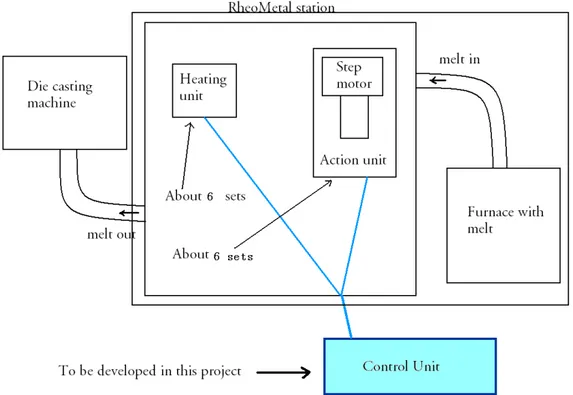
RheoMetal AB has developed a new technology – RHEOMETALTM
process for dosing and transfer of molten metal from a furnace into a die casting machine. Presently a patent is pending for this technology. The process is schematically shown below.
Figure 1-1 RheoMetal station
This master project focuses on developing the Control Unit which can further subdivide into Heating unit and Action unit using PLC control, for the Heating unit, thermocouples will be used to detect the temperature of piston, and give information for control unit to control them. The accuracy control will be 2 0
C. For the Action unit the actions should be fulfilled through step motors. Around 6 sets step motors will be used, the volume accuracy must control within 2%. In this system temperature control and cooperation between different actions are very important.
Stepper motors will be used to dosing and transferring action, but stepper motor can never move if the temperature on pistons is not correct.
The thermocouples will detect the temperature of the heating unit, and feed back to the control unit. If the temperature is below the preset temperature, the heating system will be turned on, if higher than the preset temperature, it will be turned off, the controlling accuracy is 2 0
A stirring device as well as a unit for producing of Enthalpy Exchange Material (EEM) is also needed in this equipment. Therefore, a control system for
controlling the stirring action of the stirring motor and actions of producing EEM (on construction, not final decided) are needed in this project. The parameters for the stirring motor include stirring speed (rpm), stirring time, etc.; the action of EEM production will be decided later on.
The project should also create a user control interface for the control system, by which all the parameters can be easily set or changed. The major parameters will be: temperature, dosing volume (or weight), stirring speed, stirring time, etc.
1.2 Purpose-Objectives
The purpose of this project is to help the company to develop a whole new casting machine which uses new casting techniques, so it need new automatic control compare to old type casting machines. For the master level, the project will give an experience to develop the whole automatic unit of machine.
The master project job includes:
1. Choosing suitable step motors according to the requirement such as torque force, linear speed, given from company, and then learning how to use those (about 6 sets).
2. Selecting appropriate heat elements and thermocouples for heating units (about 6 sets)
3. Counting the number of control signals, and then deciding appropriate PLCs. It is possible use several PLC units to control separate units.
4. If it is possible, developing a testing machine to Program the PLCs that chose, and then testing them.
5. Communication between different units in order to cooperate each other. 6. Choosing appropriate peripheral devices for control system
7. For future maintenance, it will be better to choose all the devices that available in current market.
8. The project also includes system simulation using SDL coordinate with Matlab.
9. A safety system should be added to system to predict to behaviour of some errors.
Because the final design for the machine is not finished yet, it will be hard to decide actual devices required, but a testing machine should first assemble successfully, which includes one step motor, some thermocouples, one PLC and some peripheral devices.
Then extend the testing machine to whole machine.
The project will stop in finishing develop testing machine and whole system simulation.
1.3 Limitations
Because the project uses a new technology in casting field, so most of the components for the designing machine should order from factories, unfortunately, it is time consuming . So in this project will not include to finish the final
machine , means that the project will not experience whole process of developing a new system. The project will only include developing a testing machine and
simulation both testing machine and whole machine. In the project, a safety system will be added to the system to insure that the machine can detect and even solve the problem when some errors ocurr during running, however,it is
impossible to model and simulate every possible error conditions. Therefore, only some common errors be simulated and try to solve them, if system need predict others wrongs, maybe it require future work in future.
1.4 Thesis outline
In the next section, a theoretical background will be described, which shows the theories that will be used to support the project; in the third section, it will introduce the method to execute the project which divides into several phases. In the fourth section SDL modelling and simulation result will be described, and it will show you how to use SDL to model and simulate a PLC control system including real machines and touch control panels, in the fifth section, the
conclusion and discussion will be employed. In the Sixth and seventh sections are the reference used in the project and the appendix with the SDL code of the project.
2 Theoretical Background
This project is to design an absolutely new machine which inside new technology patent will be applied.
To develop a whole automatic system, much background knowledge is necessary such as PLC programming, stepper motors controlling, PID control, and so on.
2.1 PLC
:PLC (Programmable Logic Controller) figure 2-1 is a digital computer used for automatic controlling of industrial processes, which originally from 1968s [1]. There also exist many different types of scheme for industrial processes for
example real-time system, DCS (distributed control system), microcontrollers. But compared with them using PLC for the automatic control designing has its own advantages,
Fig2-1.Mitsubishi and Simens module PLC
2.1.1. Advantages of PLC
Firstly, short time from design to market: designers don’t need to design PCB, they don’t need to design electric components, every electric components for example relays is available in market, what they need to do is to buy them then assemble them together to form a control system.
Secondly, good ability of extension in future, for the future extension, unlike microcontroller control systems which need reprogram microcontroller, redesign PCB board, and reassemble all components, a PLC dominated control system (module PLC) only need to add some new modules (I/O modules or function modules), then reprogram the PLC, and extend assemble some electric
Thirdly, convenient for maintenances, sometimes machine faults are inevitable, if engineers maintain a microcontroller dominated system, if a PCB broken, they usually must discard whole PCB, maybe including components on it, but if it is a PLC dominated system, they only need change a new module or CPU to displace the old one, it is quite easier .
Fourthly, good flexibility for modifying or redesigning in future, if designers are designing a new industrial automatic control system, PLCs have benefit to modify and redesign, nothing need to be changed, the only need is reprogramming the PLC then rewire the electric components
Of course a PLC has its disadvantages. For example, it is suitable to control dominated systems but no very good at data process dominated systems, another problem should be response time with environment, because a PLC works generally go though three important steps, check input stats, execute program, update output stats [3], see figure 2-2, so , for example, if a PLC main scanning cycle is 300ms, the longest response time to environment will be 600ms, but in industry control requirements, general using replays to control actuators, such response time is acceptable. So in the project PLC dominated controlling design will be better.
Figure 2-2 PLC scanning cycle [3] 2.1.2 PLC classification
According to them structures, PLCs can be divided into compact PLCs (integral almost everything together into a box, good price but bad extension ability) and module PLCs (easy to extend but costly compare to the former).
According to them functions, PLCs can be divided into low-end PLCs (only some very simple functions for example timer available), middle-end PLCs (include more functions such as PID control), and high-end PLCs (include powerful functions from mathematic compute to internet communication).
According to them I/O numbers, PLCs can also be divided into small PLCs (I/O less than 256), middle PLCs (I/O from 256 to 2048) and large PLCs (I/O is greater than 2048).
2.1.3. PLC programming languages
The international standard IEC 61131-3 currently defines five PLC programming language for PLC system: FBD (function block diagram), LD (ladder diagram), ST (structured text), IL (instruction list) and SFC (sequential function chart)[4], IEC 61131-3 is the third part of the open international standard IEC 61131, and was first published in December 1993 by the IEC. The current (second) edition was published in 2003.Part 3 of IEC 61131 deals with programming languages and defines two graphical and two textual PLC programming language standards, All of the languages share IEC61131 Common Elements. The variables and function calls are defined by the common elements so different languages can be used in the same program.
FBD: A function block diagram (FBD) is a graphical programming language; it describes a function between input variables and output variables. A function is described as a set of elementary blocks. Input and output variables are connected to blocks by connection lines. An output of a block may also be connected to an input of another block, for example see figure 2-3
Figure 2-3 Siemens S7-300 FBD [19]
LD: an LD (ladder diagram) is another very popular graphical programming language for PLC; it was originally invented to describe logic made from relays. The name is based on the observation that programs in this language resemble ladders, this language is very suitable for workers whose have few engineering background but have more practice of implementations, and figure2-4 is a simple LD sample.
Figure 2-4 S7-300 LD [19]
ST: ST (structured text) is a high level PLCs program language and syntactically resembles Pascal, complex statements and nested instructions are supported in structured text, a simple example see figure 2-5.
Figure 2-5 Siemens S7-300 ST (SCL) [19]
IL: An IL (instruction list) a programming language designed for PLCs, compare with ST, it is low level language and resembles assembly language. See figure 2-6.
Figure 2-6 S7-300 IL (STL) [19]
SFC: All of the previous methods are well suited to processes that have a single state active at any one time. This is adequate for simpler machines and processes, but more complex machines are designed perform simultaneous operations. This requires a controller that is capable of concurrent processing - this means more than one state will be active at any one time. This could be achieved with more mature techniques such as Sequential Function Charts (SFC) [5].
Sequential Function Chart (SFC) is a graphical technique for writing concurrent control programs. The three main components of an SFC are steps, actions and transitions. Steps are units of programming logic that accomplished particular control tasks. Actions are the individual aspects of that task. Transitions are the mechanisms used to move from one task to another. Figure 2-7 is an example of SFC program code using in Siemens PLC.
Figure 2-7 S7-300 SFC (GRAPH) [19]
manufacturers in order to give convenience to users who have bad programming background, but good engineering background, they designed some higher level programming languages for PLCs, for example Siemens S7-HIGRAPH. It is a good product for sequence control, it is self documenting and sufficiently "non-programmer" orientated that the control features of the program can be
demonstrated easily to someone with no ability in programming languages.
HiGRAPH uses a compiler to generate STL(IL) code, in fact PLC's in HIGRAPH all run STL code and the rest is only the way it is visualized[6], see figure 2-8
Figure 2-8 S7-300 HI-GRAPH [19]
HIGRAPH divides a system into several blocks, each block uses function state charts to program,in this way, it is possible divide a project into several different function units, and each function units will at different state at same time, state transition can through some defined conditions.
To program PLCs there are many different languages. But it is very hard to say which one it is better or which one must be discarded. Every language has its advantage and good for a group of programmers to use.
Someone who are good in programming background but do not have so well engineering background. ST and IL will be good choices, someone who have many practices in implementation experiences; LD will be good for them. someone who lack background of PLC programming but have good engineering background, there are some other choices, SFC or HIGRAPH should suitable to them, fortunately, almost every PLC manufactures now support conversion between two different programming languages, it make PLC users communicate each other easier.
2.2. Stepper motors:
Stepper motors are actuators that can convert digital pulse signals into mechanical angle movements or linear movements. Unlike normal motors which rotate continuously, stepper motors rotate step by step, advantages of stepper motors include low cost, high reliability, high torque at low speed, and without accumulate error, when accurate control movements are required, employing stepper motors will be a good choice[7],
Figure 2-9 Stepper motor control
Figure 2-9 show how to control stepper motors, therefore, in order to control
stepper motors, at least three components needed: indexers, drivers, and stepper motors. Indexers create pulse signals to drivers, each pulse always means one step movement, and then, drivers convert these pulse signals into motor current to drive stepper motors to move.
There are mainly three type stepper motors available in market, VR (variable-reluctance) stepper motors, PM (permanent magnet) stepper motors and HY (hybrid) stepper motors, what are different features between them, there are many introductions available in internet [7].
2.3 PID control
User interface
indexer driver Stepper
motor High-level command Step pulse Motor current
PID (Proportional-Integral-Derivative) controller is the most common close loop (or feedback) controllers in industrial control systems [8]. It tries to correct error between measured variables and desired values by PID calculating and decide output a corrective action that can adjust the processed. Sometime P, PI, PD control are also be used, it depends on the control requirements, for easier to understand PID control, sometime it can consider P as “Now” control which make a change to the output that is proportional to the current error value. And I as ”Past” control which determines the reaction based on the sum of recent errors, and D as ”future” control which determines the reaction based on the rates at which the error has been changing. If use an algorithm to express PID control it would be
MV: manipulated variable
Kp: proportional gain, a tuning parameter Ki: integral gain, a tuning parameter Kd: derivative gain, a tuning parameter e (t): error
t: time
It is possible to modify control reaction through change different tuning parameter i.e.: Kp, Ki, and Kd.
PID controller can also represent as block as figure 2-10
Figure2-10 PID controller block [8]
There are usually two ways to PID controller to control temperature, one is named relays control, the other is voltage control, relays control will divide heat time into small time slots, after calculation to decide how long the relays should turn on (power turn on) at each time slot, voltage control uses PID algorithm to work out the voltage needed to heat unit in order to get the setpoint temperature.
2.4 SDL simulation
SDL (Specification Description Language) is useful software that use to specific and describe real-time and distributed systems at high level. It is defined by the ITU-T (Recommendation Z.100.) Originally focused on telecommunication systems, its current areas of application include process control and real-time applications in general. It make possible to model system before implementation. The first version of the specification language was released in 1976 using graphical syntax. The textual form was introduced later for machine processing. In 1988 SDL-88 was released containing object oriented concepts as inheritance, abstract generic types etc. The version released in 1992 had among other features an improved implementation support. SDL-2000 is the latest released version completely based on object-orientation. This version is accompanied by an SDL-UML-Profile [9].
SDL always combine with MSC (Message Sequence chart), MSC is a graphical and textual language for the description and specification of the interactions between system components, it may be used for requirement specification, simulation and validation, test-case specification and documentation of real-time systems [10].
SDL is good at control dominated systems (for example coffee serve machine) and discrete system (events happen is no continuous such as ATM machine) and reactive system. It specific and describe system in FSM(finite state machine) way, in SDL process have many different states, But unfortunately SDL is no good at modelling or simulating data managing and processing dominated system. In this project, using PLC to control stepper motors, DC motors and some values, they communicate with each other though digital signal not analogue signal, it’s a control dominated system and the control events are discrete, so it is good for the project to model and simulate the system using SDL before implementation. The main components at SDL are blocks, processes, signals and channels and data types. See figure 2-11
Figure 2-11 SDL blocks, process, signals and channels [9]
A block can be considered as an object, it describes system from architecture way, one system at least has one block, of course, it can have many block, a block can also be sub-decomposed into sub-block, for example, in this project, touch panel controller can be a block, PLC system can be a block and real machine be another block.
A process describes system from behaviour way, SDL describes system behaviour as concurrent extended finite state machine, states transition combine with handling with data movement and computation.
A signal and channel describe system from communication way, at SDL, it is necessary to transport information between different processes or blocks, signals and channels give a good solution, a channel can include many signals.
SDL accepts two ways of describing data, abstract data type (ADT) and ASN.1. The integration of ASN.1 enables sharing of data between languages [11], as well as the reuse of existing data structures. The ADT in SDL is very suited to a specification language. An abstract data type is a data type with no specified data structure. Instead, it can be used to specify a set of values, a set of operations by users. This approach makes it simple to map an SDL data type to data types used in other high-level languages.
3. Station: Design and Implementation
In order to make project easier to execute, the project process will be divided into several different phases: beginning research, information gathering, literature review, system simulation, Prototype construction and result report. All the phases will be described more detail in following sections. See figure 3-1.
Figure 3-1 Project plan and Phase’s description Beginning research phase
In beginning of research, some questions must be solved: the machine is new or old? What are the exact actions the system requires? Which control system is better for the designing, PLCs, microcontrollers, or something else? What kinds of
knowledge are necessary for the project? Information gathering phase
In this phase, it should find the ways to gather information which are necessary for designing; at generally, it can through internet or contact to electronic
components’ suppliers Literature review phase
Begining research Information gathering Literature review System simulation Prototype construction Result report
Here the roles include understanding how to control stepper motors using PLCs, how to control temperature using thermocouples through PLCs, and how execute PID control, of course including how to program PLC that have already selected. System simulation phase
A system simulation is necessary because it can give designers prediction about how the system works, it can save amount money and time to test what they design, the project will use SDL to simulate the system, SDL is good at simulating control signal dominated systems but bad at signal processing, Matlab, as an assistant software be used to show the PID control result of the project. Prototype construction phase
The prototype construction phase focuses on assembling a testing machine, that can carry on a part of important actions of the project requirements but not all, if the testing machine can act what the system requires without any errors, then it can expand the testing machine to whole machine, prototype construction can simple designing and save lots of money and time to keep modify a quite complicated system.
Result report phase
After the testing machine is developed and simulated as well as the whole machine simulation, a report must be employed.
2.1 Controller: Design and implementation
Following more detail about processing the project from the first phase-beginning research phase to the last phase will be described.
2.1.1 begining research phase
The casting machine in this project is supported by new technology-RHEOMETALTM
process, it is absolutely a new machine, it mean it should develop from nothing, the roles of this phase will focus on understanding the control requirements, research the solution for the design, figure out the electric components the project needs.
Developing the machine need control 6 sets stepper motor and 6 sets
thermocouple, because the whole machine will be put into a sealed furnace, and only a set of heat bar surround the furnace which mean only one heating unit, it also need control several DC motors and valves, so the main electric components should be stepper motors, thermocouples, DC motors, valves and bar heat. There are several possible solutions can be chose, such as DCS, microcontroller system. Compare with each other that already be done in theoretical background, PLC domain control is suitable for the designing system, and a PLC I/O number evaluation will be done in order to decide which kind of PLC must be used.
Electric
component Stepper motors Thermocouples Heating units others Unit
Number(piece) 7 4 1
Analog I/O 0 4 input 0 0
Digital I/O 11 input 0 1 output 12 output total Digital I/O:24, analog I/O 4
So the total I/O is 28, including 4 analog input and 24 digital in/output, for future extension it always need add 30 percent I/O [2], it total 37 I/O. it also include 2 function modules that can be indexers of stepper motors (one Siemens function module can maximum support as 4 stepper indexers), because normal the compact PLC cannot support 7 pulse outputs, so the module PLC for the
designing will be more suitable. 2.1.1.1 PLC selection
Here is a very good consideration list for choosing a PLC [12]; it can be a good guideline for someone who want to choice a suitable PLC for them designing, if they doesn’t have very good experience in selecting and using PLC.
Table 3-2: PLC selection consideration list
Figure 3-2 PLC selection consideration [12]
There are many different PLC vendors available, almost every vendor have same level module PLC is suitable for the project, for example Siemens S7-300,
Mitsubishi Q-system, Omron CJ serial [13]. Choosing between them some points must be put in mind.
1. Experience. It is no good for a PLC user to use a PLC that he is not familiar to, if he has more experiences at a type of PLC; this PLC should be higher priority at choice.
2. Technical support. For a new PLC user technique support will be a very important element, it can save you lots of time when you have doubt in using PLC.
3. Availability, sometime not all PLCs is easy get from local place, if you must book PLC from other cities even other countries, it should be time consuming. So PLCs that are available from local place should be put in high priority, 4. Reliability, for industry machine, reliability is quite important; fortunately
many famous PLC vendors have reliable PLC in market.
5. Economy, it always be one of important factors when designing an industry machine.
According to mention factors above, Siemens S7-300 serial PLC is suitable PLC for the project. It is a module PLC, a good way to configure the hardware of designing is to ask for help to Siemens technical support, in the same time some research should be done to familiar to Siemens S7-300 PLC, now the
configuration already decide:
S7-315CPU+1SM331 (8 analog input) +2SM321 (16 digital input) +1SM322 (16digital output) +2FM374-2(each function module can control 4 sets stepper motors).
S7-315 CPU integral standard PID controller, so no additional PID controller required. There are two different ways for PID control, relay output and voltage output, the project will use relay output.
2.1.1.2 Stepper motor select
Select stepper motors also include select driver. It better ask for help to stepper motors manufacturers. In order to choice good stepper motors for the project they are many factors must be provided to suppliers
1. torque requirement
2. needed speed in rev/sec or steps/sec 3. standard motor or with encoder feedback 4. standard leads or with cable
5. environment
For the driver also need provide some factors to vendors. 1. Controlled by PLC or PC or direction signal
2. with a serial command like RS232/485 or CAN bus 3. The number of axis to be controlled
4. How many step motors work at same time?
2.1.2 Information gathering phase
This phase actually can work with the first phase concurrent, the mainly methods to gather information for next phase-literature review is contact to PLCs or other electric components suppliers for advices or some catalogs, internet is also an useful source if you feel information is not enough to support for the project.
2.1.3 literature review
This phase will focus on learn how to using PLC, how to program PLC, how to control stepper motors using PLC and PID control, it will be best if every step some materials to support if you don’t have enough experiment of using them, and modeling and simulating system using SDL.
Use PLCs to control electric or mechanic units is the most common popular among all methods because of its flexibility and easy to be mastered by unskillful workers, in order to save the money that need to change design and also can make projects execute before PLC transported , there are many different simulation tools available to PLC for example PLCSIM tool[14], CX-SIM1.3[15], GX-simulator-C and so on, but all these simulating software have problems, first, they are no compatible each other, PLCSIM is used by Siemens PLC but cannot be used at others, same, GX-simulator-C is used by MITSUBISHI PLC not compatible to others, another problem is all PLC simulation software only simulate inside PLC, they no including real machine, the programmer can only input some signals then found out how about PLCs they using output according them programming at PLCs. The processes about whole machines is invisible, this PLC simulation can only confirm PLCs can work what systems require, but it is hard to make sure the whole system can work like you want.
Because the reasons mentioned above, the project will try to develop simulation system at system level instead of PLC level, both PLC behavior simulation and real machine behavior simulation should be included system modeling and simulating, there are many software available such as SDL, systemC and MatLab, all these software can use to simulate at system level, SDL is good at discrete signal system and control dominated system, MatLab is perfect at data process dominated system, systemC is good at communicating dominated system, Per Bjureus et al[16]propose a design methodology that called MASCOT to combine SDL simulation with Matlab simulation, P.COSTE et al[17] also introduce an approach to codesign using SDL and Matlab . In this project, PLC is a control dominated system, SDL modeling and simulating is enough. So it will use SDL to simulate the system.
Because SDL is one of most common software to model and simulate a control dominated system, so there are a lot of experiences have been done using SDL to specific system[18], but there are few experiences to use SDL to model and simulate a PLC control system, because PLC control system have some different features to other discrete system for example ATM, PLC run a main cycle, every beginning of its main cycle, it will scan all its input through its input modules, then after finish running its program which defined previously, the result will be out the at same time. Also there is much different PLC simulation software to users, this software sometime is design for special PLC, so many PLC users would like just use this software to simulate ignoring to include real machine into. In this project both PLC and real machine, even control panel will be modeled and simulated.
2.1.4 system simulation and Prototype construction phase
In fact they are two phases- system simulation phase and testing machine developing phase, but it is better to execute them concurrently because both of them can affect the other, through system simulation the designing can modify some errors beforehand, it can predict the problem on the machine. Developing a testing machine is necessary when the machine is quite complicated, it can save time and money for changing design if the problem on the project can find at testing machine, in the project, developing a testing machine only including one stepper motor and two thermocouples to control, the purpose of this machine is testing the feasibility of machine designing, if some materials can bear quite hard environment without any broken or leakage, at the same time it also give
experience about how to use PLC to control stepper motors and how to use PID controller which is integral into PLC to carry out temperature control.
For the system simulation, SDL is used to simulate the system, because it is a very good system specification and description language, it very suitable to simulate the system that control dominated. Matlab will be assistant software to show temperature control result of system simulation.
After system simulation and testing machine all work well, then designing at testing machine and system simulation can be expanded to whole system, to develop a completely machine, unfortunately, the time is limit, so for master project will only stop at testing machine and whole system’s simulation, the whole real machine development will after this project as future work.
2.1.4.1 Prepare phase
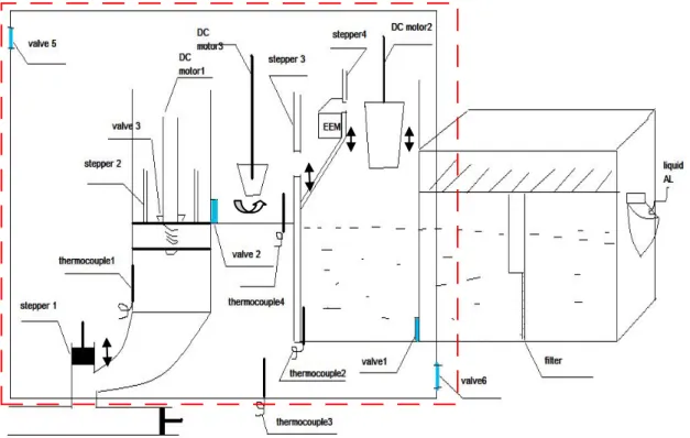
At this phase, understanding the system behavior and requirement is necessary, the outline of system as figure 3-3,
Figure 3-3 Designing system outline
from the figure know, the project need control 7 stepper motors, 6 valves, 3 DC motors, because SDL is modeling PLC control system, it is better to use same name as PLC I/O in SDL modeling, following is control points represent when modeling
Table 3-3: Digital input
Stepper Top PLC I/O Bottom PLC I/O Step1 Sensor1 I0.0 Sensor2 I0.1 Step2 Sensor3 I0.2 Sensor4 I0.3 Step3 Sensor5 I0.4 Sensor6 I0.5 Step4 Sensor7 I0.6 Sensor8 I0.7 Step5 Sensor9 I0.8
Step6 Sensor10 I0.9 Step7 Sensor11 I0.10 Table 3-4: Analog input:
Thermocouple Temperature1 Analog I/O Thermocouple1 For PID control A0
Thermocouple2 For monitor A1 Thermocouple3 For monitor A2 Thermocouple4 For monitor A3 Table 3-5: Digital output
Control units PLC I/O Control units PLC I/O Valve1 O5.0 Valve2 O5.1 Valve3 O5.2 Valve4 O5.3 Valve5 O5.4 Valve6 O5.5 DC motor1 power O5.6 DC motor2 power O5.7
DC motor2 direction O5.8 DC motor3 power O5.9 Band beater power O5.10
PLCs have many different programming languages available now, for example LD, FDB and so on, in this project SFC or HI-GRAPH will be good a choice, they program PLC as a state machine see figure 2-7, figure 2-8, so It is possible to model system as a state machine too, divide system into several different states, each state does a special task. In this case system will be divided into initial state, standby state, EEM state, stirring state, and transfer state. As its name indicate each state have a special task to do. See figure3-4
Figure 3-4 State description
Initial state execute when power on or new casting components be set, in this state every stepper motors will move to its initial position, and wait temperature reach a suitable value.
A timer should be put at initial state, if after timer timeout initial still no finish its initial, meaning initial fail(sensors at machine cannot detect stepper motors reach them initial position), the system should be stop and stepper motors check should be done. If initial success, the system will enter next state-standby state.
At Standby state, the main task is calculation, according parameters from touch control panel, the calculation task should calculation including transferring time of each one cycle(it depend on the weight of casting component), slurry weight and cycle time(it depends on the weight of slurry). It also including initial some number of stepper motor delay time and timer waiting number. If
EEM state is the state that design for making EEM for system, first induce liquid aluminums into a calculated vessel see figure3-3, put a designed stick into liquid aluminum (stepper motor 6), then turn on cool system a defined period to make liquids solidify and cool down, use stepper motor 5 to transport EEM to the other stirring vessel for making slurry see figure 3-5.
Figure 3-5 EEM system
Next state is stirring state; this state task is simply, use stepper motor7 put down EEM then use DC motor 3 (see figure 3-3) turns on a defined period, then slurry finish.
When slurry is ready, next coming is transferring state, it is the last state at this system, because the fluidity of slurry is different to liquid, it is quite low, so system need a screw to help transferring task, screw turn on when piston move up, but turn off when piston move down. When transferring state finish, if casting component parameter be changed, it will go back to standby state, execute next cycle, if change a new casting component it should process from initial state again. The action units’ movement list will be described as following:
A. Initial: period: 50 seconds,
Stepper motor1 to stepper motor7 go to them initial position, Valve5 and valve6 turn on make protect gas in,
Four thermocouples be used to control and monitor temperature (PID control) to make sure system temperature reach suitable point.
B. Standby: period: almost 0 seconds, No action units’ movement
Step motor3 and step motor4 move down according the step numbers calculated, DC motor2 move down at same time, then step motor3 and step motor4 move back to initial position, valve4(cool system) turn on 10 seconds, then turn stepper motor5 180 angles.
D. Stirring state: period 15 seconds,
Stepper motor3 move down, then DC motor3 turns on 12second, then move stepper motor3 up
E. transfer state:
Stepper motor2 move up, same time DC motor1 turn on, DC motor turn off when stepper motor2 reach top, valve3 turn on,
Stepper motor2 move down according the step number calculated, wait timer then move up or down. Valve3 off when move up, on when move down. For the system’s PID control, for more explicitly show the result, temperature changing record with both time and temperature in SDL simulating will output as a txt document see figure 3-6, use MatLab to read the document, and make a explicitly graph about temperature change according time. More detail will be introduced at result part.
Figure 3-6 SDL combine with Matlab
Besides modeling behaviors of whole machine, a safety system will be added to the system, safety system use to detect and response any possible wrong happening. In order to test safety system, the project create a new block named error creator which can create some defined wrong to safety system, then check the response about safety system.
2.2 Controller: units and system modelling
The project goes through beginning research phase, information gathering phase, literature review phase, prototype construction and system simulation phase. Controller use SDL to model system, including both testing machine and whole machine, though testing machine is simple, only one stepper motor and two thermocouples. Compare with two machines, the SDL modeling and simulating of electric components should be same. Following some detail modeling method about electric components is described.
2.2.1 Stepper motors
A stepper motor behaviors modeling in SDL need create three blocks, i.e. indexer block, driver block, stepper block. See figure 3-7(1),figure3-7(2).
Figure3-7(1) stepper motor SDL modeling
Figure 3-7(2) stepper motor SDL modeling
These three blocks model real stepper motor work, PLCs can act as indexers Drivers convert move commands that from indexers to power signal, steppers move as drivers want. Stepper motors behaviors modeling in SDL see figure 3-8
Figure3-8 stepper motors’ behaviors modeling in SDL
In this figure we can see stepper motors use two position sensors to find initial or end positions, they convert move signals into distance.
2.2.2 Heating units:
because the project uses relays to control temperature, so the temperature change up to how long relays turn on, to simulate heat unit behaviour, need count the during of relays turn on. But SDL data type is very strong, duration type get from SDL cannot use in real type calculation because of different type. To solve this problem, a 1time unit (ms) timer will be used. See figure3-9
Figure 3-9 Heat units modelling
Show in above, thermocouples will sample system temperature each 20 time unit (ms), one time unit timer and a counter use to count how many time units relays be turned on in one 20 ms duration, the use counter result to calculate for it is real type.
2.2.3 PLC behaviours modelling
SDL should also model and simulate PLC behaviour for example I/O, CPU execute. Some inputs in PLC are digital for example sensors, they can be considered as discrete input, but some inputs are analogue for example
thermocouples, they should be considered continuous input, but SDL can only handle discrete events, to model this behaviour, a buffer will be use, because PLCs are scanning execution, the buffer will continuously save and update analogue value, only transmit to PLC CPU when it requires. As mention before a PLC CPU is scanning execution see figure 2-2, a timer will be used (T100),when timer T100 time out, system will return to scan state and send to requires to all input block then continuous the progress of last cycle. See figure 3-10
Figure 3-10 PLC scanning execution modelling
2.2.4 Whole machine modelling
Compare to prototype machine simulation, whole machine simulation will include more electric components, for example more stepper motors, valves and DC motors, behaviours simulating of each electric components is same to
prototype machine, the whole machine simulation will focus on system behaviour instead individual component.
Firstly system will be decomposed into three main parts, touch panel part, PLC part and machine part; these part can be farther sub-decomposed into more detail sub-part, for example PLC part can consist input part ,output part, function part and so on. Of course later an error creator part will be added. at SDL system level, each part is represented by its block, touch panel part represent real touch control panel PLC part use to model real PLC including I/O modules and function modules, machine part modelling real machine which should including 7 stepper motors, 6 valves, one ban heater and 3 DC motors, error creator part use to create some defined error to safety system. See figure3-10
3-10 SDL system level block
Lots of signals must be declared in system level, in order to let SDL code more readable, signal list declaration and ADT types be used see figure3-11 figure3-12.
Figure 3-12 Signal list declaration
At PLC block, It can farther divide it into several blocks, because of modelling real PLC system, so It will also be decomposed as real PLCs: including digital input, analogue input, PLC CPU, PLC function block (FM374) and digital output, but SDL system is a event-case system, it cannot response continuous signal, in this case thermocouple input is a continuous signal, sample about 20ms, to solve this problem, SDL modelling use analogue input process to refresh thermocouples input every sample time, but no transport to PLC CPU, only when CPU need check input stats, CPU will give a requirement to analogue input, then analogue input module will give its current value to CPU, digital input module will work at same way, but touch control panel work at different way, it communicate with PLC through BUS, PLC CPU can response its signal immediately. See figure 3-13.
Figure3-13 PLC block description
PLC CPU block work as real PLC CPU which has a main cycle time, at each beginning of main cycle time, CPU will send requirements to both of analogue input and digital input modules to read the stats of environment, then after execute program that defined, output to digital output module. Just like testing machine.
Real PLC CPU will work as figure3-14.
Figure 3-14 Siemens S7-300 CPU execute graph
Above show have a real PLC CPU work, OB1 is a main cycle, this cycle will execute periodic, inside OB1 CPU can call other functions such as
FB1,FB2,SFC1, after function execute finish, CPU return to main cycle and wait for next cycle come.
When SDL modelling, it also define some procedures for example PID control, initial, and so on, for PLC CPU calling them, because the project have seven stepper motors, and when a stepper motors procedure be call it cannot be used in another stepper motor, it must when stepper motors stop working. So it need seven stepper control procedures for seven stepper motors, and system modelled system as a state machine, farther divide some state into more detail state for example, EEM state It depart into EEM1 and EEM2 states ,It put the state task into state procedure, see figure 3-15.
Figure 3-15 SDL procedure call
PID control: temperature control is a important task in the project, Siemens PLC CPU support a PID algorithm control, it also be used in system simulation, at beginning of main cycle, after scan analogue and digital input the CPU will call PID_control procedure see figure 3-15, inside PID_control procedure there is a PID algorithm calculate the output result to digital output. In order to show explicitly temperature control result in SDL simulation, It will also output both time and temperature value to a txt document which can be read by MatLab see
figure3-16, the result will be show as a graph with time according to its current
temperature, to save time and value outside SDL as a txt document, some processes must be done.
Firstly, declare a including at system level see Figure 3-16.
Secondly, it needs write some codes to open and write and close file see figure3-17
figure 3-18
.
Figure 3-17 Record procedure and textfile type declare
In this case, when SDL receive a new temperature value, it will open a file named data.txt, and then save both current SDL time and the temperature value, then close the file waiting next cycle.
2.3 Controller: system Simulation and result
SDL combine with MSC to specific and describe system, so simulation will show at MSC way.
Figure3-19 shows how a PLC controls a stepper motor, PLC_CPU send a control
command (including direction and step number) to PLC function block (here as indexer), indexer translate control command to stepper driver, then stepper driver will translate step number to distant movement(convert each step to a pulse) for stepper motor, stepper motor is the final actuator, it will process as stepper driver require, if stepper motor reach top or bottom, top or bottom sensors will detect it, then send a signal back to PLC.
The behaviour of heat unit see figure 3-20, from figure3-20 we can see the temperature refresh every 1000ms
Figure 3-20 Heat unit behaviour in SDL
The temperature result of PID control is input to MatLab then show as a graph in MatLab compare time to temperature, see figure 3-21.
Figure3-21 PID control graph
Touch panel: when someone want control the machine for example activate machine, he will input some requirements, the touch panel will turn on a timer and require input a password, when and only when the password is correct and input during timer no timer out, the control command can be transport to PLC, otherwise it's a invalid control command. See figure3-22.
Figure 3-22 Touch control panel MSC graph.
As mention before, whole system modelling and simulating will focus on system behaviour simulation. See figure 3-13 system behaviour is divided into several different behaviours; these behaviours will be farther divided into more detail behaviours. Each of behaviour will represent one state for example initial state will have initial behaviour that let all stepper motors go back to initial position, every state have a indicated bit that indicate the state be activated or deactivated, if activated task according to this state should be processed. See figure
Figure 3-23 PLC CPU initial state
Figure 3-23 show PLC CPU part simulation, at initial state, when start command
be inputted from touch panel, SDL initial indicated bit will be true, mean CPU will execute its initial state’s task, the CPU enter initial state, call a procedure named initial, inside initial procedure call other stepper motors control
procedures, and then will wait a defined period for initial finishing. The Figure shows the behaviour of initial state.
When the initial state finish its indicated bit will become false and the next state’s indicated bit will become true, meaning the next task will be executed, in this case the next state should be standby. When calculation job finish standby’s indicated bit will be false and EEM1’s will be true, system into EEM1 job. See 3-24.
Figure 3-24 PLC CPU EEM1 state behaviour
Figure 3-25 shows how EEM1 state transits to EEM2 state, when EEM1 task finish (T_EEM1 time out), its indicated bit (EEM1) will become false, and then next state’s indicated bit (EEM2) will become true.
Figure 3-25 State transition
Whole system modelling and simulating also includes a safety system, safety system be divided into two part: temperature part and action part, a error creator process used to create errors for simulation, safety system process used to detect errors and then response these errors, figure 3-26(a-d) show a temperature error behaviours.
First environment input a modelling requirement, so a temperature error signal created, see figure3-26(a), the signal will be consumed by error creator process, it will makes machine process output temperature that out of limit, see figure3-36(b), and then safety system should detect this problem, then send a temper_problem signal to PLC CPU, PLC CPU will stop, waiting temperature problem be solved by engineers. See figure 3-36(c-d
Figure 3-26 Temperature error (a)
Figure 3-26 Temperature error (c)
Figure 3-26 Temperature error (d)
It is hard to describe each state transition at this section, so the project only shows some important state transitions, the detail code and simulation result will no included
3 Conclusion and discussions
The project gives opportunity to experience developing a control system from original state. It is absolutely time consuming, a lot of work should be done before reach result, such as information together, and market investigate and so on. So in order to save time and recourses, a systematic way to process designing is
necessary, the way should divide system designing into several different phases, each phases work different job, it can give designers more directional and playful way to develop the designing system, in this case, It will be divided into beginning research, information gather, literature review, system simulation, prototype construction and result report phases, each phase have some special job must be done, it make me easier to execute the project.
Of course, phase’s division is not fixed; there should be a better way to plan the designing. Each phase also possible sub-divide into more detail and more
directional sub-phase, this can be as future work for this project. Future works also include adding for more safety schemes to system, and finish whole real machine. This project also proves that it is possible use SDL to model and simulate a PLC control system including all components, SDL software is good in discrete signal specification and description, but continuous signal such as thermocouples signal also is possible modelled by SDL.
4 References
[1] Hugh Jack(2007); Automating Manufacturing Systems with PLCs Version5.0 pp36-pp325
[2] W. Bolton(2006); Programmable Logic Controller fourth edition,Newnes, ELSEVIER, ISBN 10:0-7506-8112-8. [3] PLC introduction http://www.plcs.net/chapters/howworks4.htm (ACC. 2008-03-09) [4] PLC language http://en.wikipedia.org/wiki/Programmable_logic_controller#Programmi ng(ACC .2008-03-09) [5] PLC SFC http://www.eod.gvsu.edu/~jackh/books/plcs/chapters/plc_sfc.pdf(ACC. 2008-03-10) [6] Siemens PLC languages http://www.automation.siemens.com/simatic/industriesoftware/html_76/produ kte/software-s7-higraph.htm(ACC. 2008-03-10) [7] stepper motor http://www.anaheimautomation.com/intro.htm#How%20Do%20They%20 Work? (Acc. 2007-12-12) [8] PID controller http://en.wikipedia.org/wiki/PID_controller (Acc. 2007-12-12) [9] SDL introduction http://en.wikipedia.org/wiki/Specification_and_Description_Language(ACC.2008 -03-10). [10] MSC introduction http://www.sdl-forum.org/MSC/index.htm(Acc.2008-03-10) [11] SDL introduction http://www.iec.org/online/tutorials/sdl/topic04.html(Acc.2008-03-10) [12] PLC selection http://support.automationdirect.com/docs/plc_selector.pdf (Acc. 2007-12-12) [13] PLC manufacture http://www.directindustry.com/industrial-manufacturer/plc-60974.html(ACC 2008-03-12) [14] PLC simulation http://www2.sea.siemens.com/Products/Automation/Engineering-Software/S7-PLCSIM+-+PLC+Simulation.htm(ACC 2008-03-14) [15] PLC simulation http://www.osuchallengex.com/files/OSU_Report_4_Final.pdf(ACC . 2008-03-14)
[17] P.COSTE; Multilanguage Codesign using SDL and Matlab TIMA labortary, Grenoble, France. [18] SDL simulation http://ieeexplore.ieee.org/Xplore/login.jsp?url=/iel5/10656/33623/01599030.pdf ?arnumber=1599030(ACC.2008-03-10) [19] siemens PLC http://support.automation.siemens.com/WW/llisapi.dll?func=cslib.csinfo&lang=en& siteid=cseus&aktprim=0&extranet=standard&viewreg=WW&objid=10805148 &treeLang=en (ACC.2008-03-10)
![Figure 2-3 Siemens S7-300 FBD [19]](https://thumb-eu.123doks.com/thumbv2/5dokorg/4670787.121952/14.892.143.760.612.773/figure-siemens-s-fbd.webp)
![Figure 2-4 S7-300 LD [19]](https://thumb-eu.123doks.com/thumbv2/5dokorg/4670787.121952/15.892.141.665.117.334/figure-s-ld.webp)
![Figure 2-6 S7-300 IL (STL) [19]](https://thumb-eu.123doks.com/thumbv2/5dokorg/4670787.121952/16.892.137.577.113.445/figure-s-il-stl.webp)
![Figure 2-8 S7-300 HI-GRAPH [19]](https://thumb-eu.123doks.com/thumbv2/5dokorg/4670787.121952/17.892.138.670.335.797/figure-s-hi-graph.webp)
![Figure 2-11 SDL blocks, process, signals and channels [9]](https://thumb-eu.123doks.com/thumbv2/5dokorg/4670787.121952/21.892.222.654.130.471/figure-sdl-blocks-process-signals-channels.webp)

![Figure 3-2 PLC selection consideration [12]](https://thumb-eu.123doks.com/thumbv2/5dokorg/4670787.121952/24.892.132.776.566.971/figure-plc-selection-consideration.webp)