TMT 2014:17
Simulation of DIDRIK
HUGO ALARCON
Examensarbete inom MASKINTEKNIK Elektronik, robotik och mekatronik Högskoleingenjör, 15 hp Södertälje, Sverige 2014
Simulation of DIDRIK
av
Hugo Alarcon
Examensarbete TMT 2014:17 KTH Industriell teknik och management
Tillämpad maskinteknik Mariekällgatan 3, 151 81 Södertälje
Examensarbete TMT 2014:17 Simulering av DIDRIK Hugo Alarcon Godkänt 2014-05-20 Examinator KTH Lars Johansson Handledare KTH Lars Johansson Uppdragsgivare Scania IT AB Företagskontakt/handledare Ann Mölleman Sammanfattning
Syftet med detta examensarbete är att simulera DIDRIK, SCANIA:s standardsystem för produktion och att utarbeta en PLC-guide för programmerare.
Den främsta anledningen till SCANIA är intresserad av detta projekt är för att DIDRIK är ett stort system och att försöka förklara det kan ta mycket tid och i vissa fall förklaringar brukar inte vara så illustrativa.
Projektet har resulterat i ett PLC-program, ett WinCC program som omfattar nästan alla funktioner i DIDRIK och en PLC- guide för programmerare. Utarbetandet av PLC-guiden för programmerare och nyanställda kommer att underlätta förståelsen för detta komplexa system. Nyckelord
Bachelor of Science Thesis TMT 2014:17 Simulation of DIDRIK Hugo Alarcon Approved 2014-05-20 Examiner KTH Lars Johansson Supervisor KTH Lars Johansson Commissioner Scania IT AB
Contact person at company Ann Mölleman
Abstract
The objective of this thesis is to simulate DIDRIK, the SCANIA's common tact and supervision system used in production and to elaborate a PLC guide for programmers.
The main reason of SCANIA's interest in this project is because DIDRIK is a big system and trying to explain it could take a lot time and in some cases explanations could not be so illustrative.
The result of this project is a PLC program, a WinCC program that includes almost all of the DIDRIKs functions and a PLC manual for programmers. The elaboration of the guide for programmers and new employees will facilitate understanding of this complex system.
Key-words
1
Abstract
The objective of this thesis is to simulate DIDRIK, the SCANIA's common tact and supervision system used in production and to elaborate a PLC guide for programmers.
The main reason of SCANIA's interest in this project is because DIDRIK is a big system and explaining it could take a lot time and in some cases explanations could not be so illustrative. The result of this project is a PLC program, a WinCC program that includes almost all of the DIDRIKs functions and a PLC manual for programmers. The elaboration of the guide for programmers and new employees will facilitate understanding of this complex system. Key-word: DIDRIK, PLC, SCADA, Step 7, WinCC, Automation.
2
Sammanfattning
Syftet med detta examensarbete är att simulera DIDRIK, SCANIA:s standardsystem för produktion och att utarbeta en PLC-guide för programmerare.
Den främsta anledningen till SCANIA är intresserad av detta projekt är för att DIDRIK är ett stort system och att försöka förklara det kan ta avsevärd tid och ibland blir förklaringar inte så illustrativa.
Projektet har resulterat i ett PLC-program, ett WinCC program som omfattar nästan alla funktioner i DIDRIK och en PLC- guide för programmerare. Utarbetandet av PLC-guiden för programmerare och nyanställda kommer att underlätta förståelsen för detta komplexa system.
3
Preface
This bachelor thesis project was performed from August 2013 to October 2013 at SCANIA IT AB in Södertälje Sweden with Ann Mölleman as academic supervisor and Lars Johansson as examiner.
To understand this bachelor thesis project, the reader should have a basic knowledge of PLC, WinCC, and script programming.
I would like to thank Mikael Santala, Ramin Ahmadzadeh, Mats Ané and Tomas Eriksson for all support during the elaboration of my thesis.
4
Table of contents
1 Introduction ... 7 1.1 Background ... 7 1.2 Purpose ... 7 1.3 Delimitations ... 7 1.4 Proposed solution ... 7 2 Abbreviations ... 8 3 Technical Background ... 9 3.1 Simulation ... 9 3.2 PLC ... 9 3.3 SCADA ... 10 4 What is DIDRIK? ... 114.1 DIDRIK hardware platform ... 12
4.1.1 SCADA Layer ... 12
4.1.2 PLC Layer ... 12
4.1.3 External DIDRIK components ... 13
4.1.4 External equipment ... 14
4.2 DIDRIK Software platform ... 15
4.2.1 PLC Layer ... 15
4.2.2 SCADA Layer ... 15
4.2.3 TIA ... 16
5 Implementation ... 17
5.1 The DIDRIK Programming’s Manual ... 17
5.2 First attempt: Trying DIDRIK with SIMATIC PLC S7-1200 and TIA ... 18
5.3 Second attempt: Simulation of DIDRIK with SIMATIC PLC S7-400 ... 19
5.4 PLC ... 19
5.4.1 The Calendar ... 20
5.4.2 The simulated production line ... 20
5.4.3 Andon ... 21
5.4.4 Reject ... 21
5.4.5 Stations tacting block ... 21
5.4.6 Generation of a new product ... 21
5.4.7 Sequence ... 21
5.5 WinCC ... 24
5.5.1 Tags ... 24
5.5.2 Scripts ... 24
5
5.5.4 Login ... 40
5.5.5 User archive ... 40
6 Conclusion ... 42
6
List of figures
Figure 1: PLC Architecture ... 9
Figure 2: Example of a SCADA system. ... 10
Figure 3: DIDRIK Overview ... 11
Figure 4: Overview of the DIDRIK hardware platform ... 12
Figure 5: PLC S7-400 ... 13
Figure 6: AS-Interface module ... 13
Figure 7: Station display board ... 14
Figure 8: Line display board ... 14
Figure 9: The torque nut runner ... 14
Figure 10: Overview of the DIDRIK software platform ... 15
Figure 11: The DIDRIK Programming’s manual ... 17
Figure 12:Activity types ... 20
Figure 13: The simulated production line and its positions ... 20
Figure 14:Workflow ... 23
Figure 15: Illustration of how to display a popup window using direct connection ... 26
Figure 16: Configuration of a picture mirror ... 27
Figure 17: Linking a tag using the tag prefix ... 27
Figure 18: System Overview ... 29
Figure 19: Process indicators ... 31
Figure 20: The weekly calendar ... 32
Figure 21: Active shift calendar in WinCC ... 33
Figure 22: Active shift calendar in PLC ... 33
Figure 23: Representation of a station in WinCC ... 34
Figure 24: Production line overview of this project in WinCC ... 35
Figure 25: The states of the station ... 36
Figure 26: Stations faceplate Andon ... 36
Figure 27: Stations faceplate - Reject ... 37
Figure 28: Stations faceplate -Wait ... 37
Figure 29: Stations faceplate – Done ... 37
Figure 30: Station board display ... 38
Figure 31: Event control popup window ... 38
Figure 32: Torque nut runner from station 1 and 2 disabled ... 39
Figure 33: The states of the torque nut runner ... 39
Figure 34: Torque nut runner pillar made in WinCC ... 40
Figure 35: Login popup window ... 40
7
1 Introduction
1.1 Background
SCANIA CV AB is a manufacturer of heavy trucks and buses. It also manufactures diesel engines for motive power of heavy vehicles, marine, and general industrial applications. In 2006 a new plant was built at SCANIA in Södertälje. This will be used for mounting drive axles and gearboxes. About twenty assembly lines would be built from the ground up with products and systems from fifty different vendors. An automation strategy was made for linking together infrastructure, communication and quality assurance; the result gave birth to an integration platform called DIDRIK.
DIDRIK was built to integrate all equipment and conveyor system so that they communicate with each other. Nowadays DIDRIK is one of SCANIA's systems for line control and
monitoring system based on Siemens PLC and SCADA.
The SCADA system of DIDRIK has been developed on SIMATIC WinCC, which is a scalable process visualization system with powerful functions for monitoring automated processes.
1.2 Purpose
The purpose of this thesis is to investigate the possibility of running DIDRIK’s PLC-program on the SIMATIC PLC S7-1200. The main purpose of the thesis is to simulate a production line that uses most of DIDRIK’s standard features. Development of the simulation and its documentation will facilitate understanding of DIDRIK for both employees and programmers. The documentation will consist of a thesis report and a DIDRIK-PLC guide for programmers, which describes the functions of DIDRIK. In case the SIMATIC PLC S7-1200 is not
appropriate to run DIDRIK’s PLC-program, this PLC will be replaced by a SIMATIC PLC S7-400.
1.3 Delimitations
There are some factors that have not been considered in this thesis. In cases when the PLC S7-1200 is not proper to work with DIDRIK, the diploma worker will replace this PLC with a PLC S7-400. The focus is to get the simulated line working and monitor various incidents during the simulated production. Due to time limits some functions of DIDRIK, like WinCC servers, K60 module, PUS, MONA, EBBA, Poka-Yoke and staff locator will not be covered in this project.
The diploma worker will use programs and codes that already have been used to develop DIDRIK, and implement them or modify them if necessary.
1.4 Proposed solution
This study aims to bring understanding on:
How to use the SIMATIC TIA Portal and the SIMATIC Step7.
Communication and change of data among function blocks, data blocks and function calls in DIDRIK.
How to make a SCADA system in the SIMATIC WinCC.
Communication between a PLC and the SIMATIC WinCC.
The properties of a torque nut runner used in the production line.
8
2 Abbreviations
FC Function Call.
FB Function Block.
DB Data Block.
VAT Variable table.
(Production)Line A line consists of a determined number of stations.
(Work)Station A station is equipped with a torque nut runner,
Andon and reject buttons and a stations name.
PROFIBUS (Process Field Bus) Bus system for process, field communication with field devices and for data communication,used in automation applications.
PROFINET A an open standard for Industrial Ethernet that facilitates the interconnection of automations system components, used for factory and process
automation, for safety applications and for the entire range of drive technology right up to
clock-synchronized motion control.
SIMATIC TIA Total Integrated Automation, software for development of SCADA and PLC systems.
SIMATIC WinCC Software for development of HMI and SCADA systems.
SIMATIC Step 7 Software for development of PLC programs.
9
3 Technical Background
3.1 Simulation
In computer science, simulation is a way to imitate a system and replace hardware equipment with computer software. The simulation tries to create the same output from the same input, as the original system does.
The simulation can be used when the system does not even exist to test how the system should work and to be able to find necessary changes to the design of the system.
3.2 PLC
A Programmable Logic Controller, or PLC, is a powerful computer designed to be a flexible platform to perform various input and output activities.
PLCs are most know as hard real time systems where a number of tasks or parameters must be completed within a determined time in response to trigger events which could result in catastrophic consequences.
The PLC hardware consists of a Central Processing Unit (CPU), Read Only Memory (ROM), Random Access Memory (RAM), power supply unit and other devices.
Since PLCs are modular systems, a number of modules are available to adapt to create the required control system. These modules include:
Analog Inputs/Outputs Communication Input/Outputs Motor Controllers Machine Vision Relays
The input module of the PLC forms the interface by which input field devices such sensors are connected to the controller and the output module of the PLC forms the interface by which output field devices such motors are connected to the controller.
Early PLCs were designed to replace relay logic systems. These PLCs were programmed in "ladder logic", which strongly resembles a schematic diagram of relay logic.
Modern PLCs can be programmed in different programming languages, from ladder diagram to programming languages such as specially adapted dialects of BASIC and C.
A PLC unit can control electromechanical processes, such as light fixtures, machinery on factory assembly lines and amusement park rides. Figure 1 shows the PLC Architecture.
10
3.3 SCADA
SCADA stands for Supervisory Control And Data Acquisition. A SCADA system is a
common process automation system that control and monitor industrial processes. The system is used to gather data from sensors and instruments from complex industrial processes located at remote sites and to transmit and display this data at a central site for either control or monitoring purposes.
A SCADA system usually consists of the following subsystems:
Data Communication.
Data Conversion.
Data Acquisition.
Data Presentation and Control.
Figure 2 shows an example of a SCADA system.
11
4 What is DIDRIK?
DIDRIK is a platform for integration of production equipment system for interconnecting production equipment in various production environments to realize tacting, traceability and production follow-up in a standardized way. In addition to storing data for traceability system tasks to visualize production and calculate real-time process indicators for presentation on display boards. The DIDRIK system is based on PLC and SCADA technology in order to provide an open system that is easy to adapt and integrate to different production
equipment’s. Figure 3 shows an overview of DIDRIK.
Figure 3: DIDRIK Overview
DIDRIK tacting system is aware of the demand throughout the flow. The process indicators, that are generated by counting accumulated work time, accumulated stop time and number of produced units provide an opportunity to constantly check if the production is on time and facilitate detection of anomalies.
DIDRIK’s functional requirements should imply technical solutions in all flows in respect to:
Poka-Yoke (Quality Assurance)
Andon Tacting Tracking Reject handling Traceability Remote diagnostics
KPI (Key Indicator)
Scheduling
Data collection and distribution
12
4.1 DIDRIK hardware platform
DIDRIK was built to integrate all equipment to communicate with each other. Figure 4 illustrates an overview of the DIDRIK hardware platform.
Figure 4: Overview of the DIDRIK hardware platform
4.1.1 SCADA Layer
As it was mentioned before, SCADA is a type of industrial control system (ICS). SCADA systems include hardware and software components. The SCADA-hardware collects data in real time and feeds it into a computer that has SCADA software installed. The computer then processes this data and displays it on a monitor or a pc screen. SCADA also logs and records all events into a database or sends them to a printer. SCADA warns when conditions are met by activating alarms.
In the production at SCANIA, the SCADA-layer is composed of servers and clients that provide production screens to follow the state of the production and store data.
4.1.2 PLC Layer
A PLC is a hard real-timesystem since output results must be produced in response to input conditions within a limited time, otherwise unintended operation will result.
PLC controls the logic of the system and handles the communication with the shop floor. In the production at SCANIA, the PLC-layer is composed of controllers and bus systems for connecting sensors and actuators.
4.1.2.1 Siemens PLC S7-400
PLC S7-400 is a modular controller for system solutions in production and process
automation in the medium to upper performance ranges. A S7-400 system consists of a rack, power supply, and central processing unit. This PLC-unit is very suitable for data-intensive tasks in the process industry and for controlling lower-level systems.
13
Figure 5: PLC S7-400
4.1.3 External DIDRIK components
4.1.3.1 Distributed I/O-modules
The AS-Interface is a protocol for networking I/O devices such as push buttons, sensors and actuators in automation systems. The Actuator Sensor Interface or AS-Interface is an
industrial connection system for the lowest process level in automation systems. Figure 6 shows an AS-Interface module used in the SCANIA production line.
Figure 6: AS-Interface module 4.1.3.2 Display board
Every line and every station is equipped with a board display in order to visualize the process indicator. The visualization boards are connected to DIDRIK using Ethernet communication. Information is broadcasted to all station display boards. Figure 7 shows a station display board used in the SCANIA production line.
The station display board displays:
Time
o For production (Counting down for each tact) o R, Brakes
o M, Meetings o S, Stops
o FU, preventive maintenance
Andon calls
o Shows in which station the problem is
Stop
14
Figure 7: Station display board The line’s display board displays:
Present production situation
Direct run
Accumulated stop time
Accumulated production situation
Figure 8 shows a line display board used in the SCANIA production line.
Figure 8: Line display board
4.1.4 External equipment
4.1.4.1 The torque nut runner
The torque nut runner is a tool connected to DIDRIK using PROFINET over Ethernet. A function block is associated with this tool in the PLC program which facilitates an easy
integration and connection to a specific station. Figure 9 shows a torque nut runner used in the production line.
Figure 9: The torque nut runner
15
4.2 DIDRIK Software platform
The DIDRIK software platform consists of SCADA and PLC technology. Figure 10 illustrates the DIDRIK software platform.
Figure 10: Overview of the DIDRIK software platform
4.2.1 PLC Layer
4.2.1.1 SIMATIC STEP 7 V.5.5
STEP 7 is a complete engineering package which supports the complete engineering workflow during a project.
STEP 7 contains convenient functions for all phases of an automation project:
Configuring and parameterizing the hardware.
Specifying the communication.
Programming.
Test, start-up and service
Documentation, archiving.
Operating/diagnostics functions 4.2.1.2 SIMATIC S7-PLCSIM
SIMATIC S7-PLCSIM simulates a controller for functional testing of user blocks and programs for S7-300 and S7-400 on the programming device/PC. The facility to simulate the communication via MPI, PROFIBUS DP and TCP/IP is new and ensures a high degree of flexibility in the simulation. (Siemens Simatic S7 PLC-SIM)
4.2.2 SCADA Layer
4.2.2.1 Siemens WinCC SCADA system
As mentioned before, the SCADA systems include hardware and software
components. WinCC is a supervisory control and data acquisition(SCADA) and human-machine interface (HMI) software package from Siemens. SCADA systems are used to gather data, transmit, monitor and control this data at a central site. WinCC is written for the
Microsoft Windows operating system. (Siemens SIMATIC Controller Software)
The major subsystems of WinCC are:
The graphics system - the editor for creating the screens is the Graphics Designer.
The alarm system - the editor for configuring the alarms is named Alarm Logging.
The archiving system - the editor for specifying the data to be archived is named Tag Logging.
The report system - the editor for creating the report layouts is the Report Designer.
The communication system is configured directly in the WinCC Explorer. (Siemens Simatic HMI - WinCC v6 Getting Started, 2013)
16 4.2.2.2 The Siemens WinCC Runtime
With the runtime software, the operator can run and monitor the process. In particular, the runtime software has the following tasks:
Reading of the data stored in the CS database.
Displaying of the screens.
Communication with the automation systems.
Archiving of the current runtime data such as process values and alarm events.
Running of the process, e.g. through specified set-points or activation/deactivation. (Siemens Simatic HMI - WinCC v6 Getting Started, 2013)
4.2.3 TIA
TIA or Totally Integrated Automation Portal is an integrated engineering framework for PLC, HMI and Drives.
SIMATIC STEP 7 V.12 is a controller software in the TIA portal. STEP 7 is the software for configuration, programming, testing and diagnosis of all SIMATIC controllers.
SIMATIC WinCC V.12 in the TIA Portal is the software for all HMI applications ranging from simple operation solutions with Basic Panels up to SCADA applications. (Siemens TIA Portal, 2013)
17
5 Implementation
5.1 The DIDRIK Programming’s Manual
During the learning phase the thesis worker created some very simple programs to test his knowledge in PLC. During this time, the thesis worker gathered information about the DIDRIK functions and started writing the DIDRIK programmer’s manual.
This manual was also part of this project and writing it posed no problems except that the manual must be written using a SCANIA Word document template for information documents. The purpose of this technical manual is to offer a description of the DIDRIK functions used with the PLC. The manual contains pictures and tables to facilitate understanding of the functions and the data types that are required for their correct functionality. Figure 11 shows the first page of the DIDRIK Programming’s Manual.
18
5.2 First attempt: Trying DIDRIK with SIMATIC PLC S7-1200
and TIA
The first attempt of simulating DIDRIK’s PLC-program on the PLC S7-1200 started off by copying a function block from DIDRIK’s PLC code to a new PLC project. The purpose of the block was setting up the clock. Further some straightforward lines of code were added for testing the communication with the integrated WinCC of TIA. WinCC showed correct results and everything was okay so far.
A migration from SIMATIC STEP 7 V.5.5 to TIA would provide efficiency with the following:
Spare staff from writing thousands of lines of PLC-code.
Lower conversion time and labor costs.
Lower engineering costs.
At the start, this work it was supposed to involve experiment and work with a SIMATIC PLC S7-1200 to test DIDRIK with a modern PLC but this was changed by a discovery. The
migrations failed and it appeared that the variables declared as BLOCK_DB and some lines of PLC-code written in STL could not migrated.
The S7-1200 does not support a data type called BLOCK_DB, which is supported only by the SIMATIC PLC S7-300/400. This data type is used in many function blocks and is vital for the correct functionality of DIDRIK’s PLC-program. Another cause of the failed migration is that the STEP 7 version for the S7-1200 only covers PLC programming languages like FBD, SCL and Ladder. Unlike S7-1200, the STEP 7 version for the S7-300/400 covers PLC
programming languages like STL, FBD, SCL, Graph and Ladder, which have been used to write DIDRIK’s PLC program.
After two weeks of attempts it was decided to terminate working with the PLC S7-1200 and TIA.
19
5.3 Second attempt: Simulation of DIDRIK with SIMATIC PLC
S7-400
This thesis is about creating a simulation device to demonstrate how DIDRIK will perform in service. To create such a demo it will be necessary to build a SCADA system that controls and displays simulated hardware. There will be no big differences building a SCADA system for a simulated PLC compared to a real one, because the SCADA system does not distinguish between the two.
This time, a migration was not necessary since the PLC code was written on SIMATIC STEP 7. The DIDRIK system that will be used as example was made for working with a PLC S7-300, so some caution will be very necessary when copying the blocks and making the hardware configuration for PLC S7-400.
DIDRIK’s PLC program contains thousands of lines of code, a big network of functions and a number of user-defined data types so the PLC programming is an important part for
development of the simulation device.
WinCC is the tool that is used for developing HMI systems. In addition to the graphical HMI, the presence of tags is essential for the functionality of the HMI system. Tags functions, just like pointers, point to various memory cells of the PLC and the HMI system. Further, it will be necessary to develop menu lists, graphics, alarm management, etc.
A WinCC database, better known as “User Archive” will be connected to WinCC in order to store incident information during the production.
5.4 PLC
The simulated hardware used for simulation of the line production consists of a PLC called SV-90400. The demo uses a PLC S7-416-4 PN/DP. The S7-400 is especially suitable for data-intensive tasks in automated process. A S7-400 system consists of a rack, a power supply and central processing unit. It can be installed and expanded in a modular way.
The Siemens TCP/IP Ethernet Driver makes possible to connect Siemens TCP/IP Ethernet devices to OPC Client applications, including HMI, SCADA, Historian, MES, ERP, and countless custom applications.
The PLC in this project uses a simulated network using TCP/IP protocol. This network is located in the PC.
There are several ways of communication using fieldbus in industry. They are used to connect PLC’s and various equipment, and thus forming a in the network. Profibus, Profinet and Interbus are names of some fieldbuses. Most of them are supported by Siemens PLC’s.
Advantages of fieldbuses
Reduce cable consumption
Operator is allowed do maintenance
Fewer errors
Fewer access points Disadvantages
Difficult to identify ground faults
Long cables favors interference
20
The protocol used in this project is TCP/IP but in the production DIDRIK uses TCP/IP, RT (real-time) and IRT (isochronous real-time). This protocol allows a connection between the PLC and WinCC.
5.4.1 The Calendar
To calculate the process indicator of the production in a DIDRIK system, it is necessary to enter data regarding production conditions into a calendar.
A calendar in DIDRIK consists of two parts:
Current calendar
Calendar for the next 14 days.
The calendar uses the clock to check if the start and stop time has passed and when a new shift is going to start. This block also contains a check whether the number of shifts has increased or decreased.
The purpose of this function block is to control the production line and the production according to inputted times and activity types. The activity types are described in Figure 12:Activity types
Figure 12:Activity types
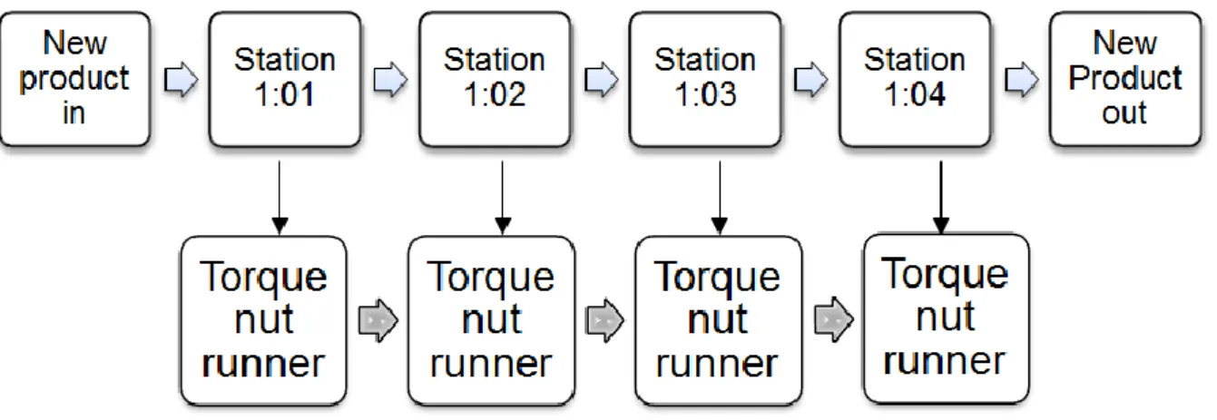
5.4.2 The simulated production line
The production line consists of four stations and every station is equipped with a virtual torque nut runner. A new tacting pulse is generated with a frequency of 60 seconds, and this will happen if the production line has finished the job before the tacting pulse time has gone. Otherwise stop time will be generated and the generation of the new tacting pulse will be delayed until the production line is okay. Figure 13 illustrates the simulated production line.
21
5.4.3 Andon
If the operator has a problem that might cause a stop, he or she will use the Andon-button to alert the Andon for assistance. The Andon call is associated with the station.
The Andon signal can be activated from the press button in WinCC.
If the Andon-button is set the station will send an alarm message to WinCC, turn on the Andon light, set the Andon variable for history and the Andon variable in the stations DB. The alarm message to WinCC will contain information with the name of the station.
5.4.4 Reject
If a problem occurs that cannot be solved at the station, the operator or Andon can choose to reject the product. The activation of the reject signal will occur via the reject button in WinCC. Logical operations will set and reset the reject variable of the stations DB via a flip-flop block. The variable for reject history will also be set at the same time. If the reject is set, the station will immediately be declared as okay and an alarm message will be send to
WinCC. The rejection will cause the specific product to pass through the line segment without any further work.
5.4.5 Stations tacting block
The stations tacting block is a FB that gathers the signals of the station from Andon, reject, the torque nut runner or other equipment and the tacting pulse. This block will also check if the job is finished before the tacting time has passed. The function block opens and copies the content of the station and tacting DBs to temporary variables to verify the clear signals from the station. The station will get a clear sign either if all the signals are clear, or if the reject signal has been activated. If the tacting time is over and the station is not clear, an alarm message will be sent to WinCC.
Finally, the data variables from the stations DB will be reloaded, and a copy of the variables will be loaded as Historia in the DB instance of this FB.
5.4.6 Generation of a new product
The generation of a new product requires that all the stations in the production line have finished their jobs and are declared as okay.
A station will be declared as okay when it has finished the job or when a product has been rejected from the station. The okay signal from the four stations will set the production line as okay. This simulates what actually happens in the real production line if the line is not okay the operators cannot introduce a new product to the line.
In the production line, products without ID are simulated. The reason for this is that the
program represents the product with a Boolean variable that indicates “product in place” when the variable is high and “no product” when the variable is low.
5.4.7 Sequence
Clicking the button called “Line auto” in the WinCC program, will immediately generate the first tacting pulse. The stations stand empty, waiting for the first tacting pulse time to finish. When time is up the user should click the button “Line ok” to simulate that the line is okay and generate the first product in the production line. The new product is moved immediately to the first station.
In the function block corresponding to the station, it is checked whether there is a new product on its way to the first station and a new generated tacting pulse and if the torque nut runner is enabled to work, then the function block will wait for the user click on the torque nut runner button in WinCC. This action will make the torque nut runner run for 5 seconds. When the product has been processed by the torque nut runner and the station is okay, it is
22
time to move the product to the next station. The function block corresponding to the torque nut runner and to the station puts the product as output and waits for the next station to pick up the product.
The next station controls primarily whether the previous station has an output product and if this is the case it moves into the station as a new product. As in the previous station, the function block corresponding to the next station checks if there is a new product and a tacting pulse. If the torque nut runner is enabled, the function block will wait for the user to click on the torque nut runner button in WinCC. This will make the torque nut runner run for 5 seconds. When the product has been processed by the torque nut runner without
complications, it is time to move the product to the next station. The same process will occur until the product has reached the last station in the production line.
When the product has left the last station, the production line will be okay.
The okay state of the production line is fundamental for the generation of a new product. Figure 14 illustrates the workflow.
23 Figure 14:Workflow •If Line ok •if New Tacting pulse •Generate a new product New Product in •STATION 1:01 •If Tacting pulse=1 •If New product in=1 •If Nutrunner action=1 Product out •STATION 1:02 •Tacting pulse=1 •New product in=1 •Nutrunner action=1 Product out •STATION 1:03 •Tacting pulse=1 •New product in=1 •Nutrunner action=1
Product out •STATION
1:04 •Tacting pulse=1 •New product in=1 •Nutrunner action=1 Product out •Line ok=1 New product out
24
5.5 WinCC
When the PLC code has been developed and tested, it will be time to add a WinCC platform to the PLC program. This platform will be called DIDRIK. The compilation of the platform will generate a number of tags linked to the variables stored in the data blocks. Some of those tags are linked to the variables that are used during checking the communication between the PLC and DIDRIK. Those variables indicate things such as the status of a work station, the status of a torque nut runner, etc.
5.5.1 Tags
Process values are observed in runtime using tags. Process values are data which are stored in the memory of one of the connected automation systems. They represent the status of a plant in terms of temperatures, fill levels or switching states, for example. The tags in WinCC represent either real values or internal values.
In WinCC during runtime, the values of the process tags are automatically determinated and entered by WinCC. These values are transferred to the automation system via the stipulated channel. The automation system controls the process accordingly.
5.5.1.1 Internal tags
The internal tags can be seen as global variables because they can be reached by the scripts from all parts of WinCC. The internal tags can be of different data types, from integers to strings. The difference between internal and external tags is that the internal tags can only be reached on WinCC and no external PLC or program can access these tags.
5.5.1.2 External tags
External tags are device tags, i.e. they are associated to some address location in the PLC. Any changes made to the value of an external tag would get reflected in the connected device (PLC).A WinCC program can communicate with a PLC program through different protocols. Profibus, Profinet, RFC 1006 and TCP/IP are just some of the standards supported. In this simulation TCP/IP communication is used between PLC and WinCC. When a tag is created, it will be connected to a specific memory address in the PLC in order to create interaction between the HMI and the PLC.
5.5.2 Scripts
A script is a program or sequence of instructions that are executed on automate processes. Most scripts used in the demo are Visual Basic scripts.
5.5.2.1 Local scripts
Local scripts are scripts located inside a WinCC object. A WinCC object can be a button, a picture, a diagram; or a text. The local scripts can only be called when for example a button is pressed. A local script, to be reused several times and called from different places in the program, will work better as a global script. An example in the demo application is when an operator presses a button that belongs to a station, a little window pops up with detailed status information.
This example shows how to set the “line auto” tag using a Visual Basic Script.
Sub OnClick(ByVal Item)
If HMIRuntime.Tags("S7Prog-SV-90400/KomP->D>Takt1.LineAuto").Read=0 Then HMIRuntime.Tags("S7Prog-SV-90400/KomP->D>Takt1.LineAuto").Write 1 Else HMIRuntime.Tags("S7Prog-SV-90400/KomP->D>Takt1.LineAuto").Write 0
25
End Sub
5.5.2.2 Global scripts
The demo program uses a global script that sets the clock. This script has been used in other DIDRIK projects.
This example shows how to set the clock in the PLC using a C-script.
SYSTEMTIME time; GetLocalTime (&time); // PLC SV-90400 SetTagWord("S7Prog-SV-90400/DbSetClock.SetClockYear",time.wYear); SetTagWord("S7Prog-SV-90400/DbSetClock.SetClockMonth",time.wMonth);
5.5.3 Pictures
The WinCC pictures are used to create a user interface. The SCADA system provides an overview of the complete production line where the stations are visible and clickable.
Most of the pictures used in this demo application have been taken from a DIDRIK project in order to keep the typical appearance of DIDRIK.
5.5.3.1 Pop-up window
The popup windows are part of the SCADA system and they are programmed in WinCC by creating a new picture contains the components that will be displayed in the pop-up window. Next a component called Picture Window is added at the position where the pop-up window will appear. The size of the Picture Window and the pop-up window should be of the same size to obtain the best appearance.
When configuring the Picture Window, the "display" option of the Picture Window is often set to "no" so that the Picture Window is not visible from the start. Creating a “direct connection” in a button will make it possible to show a pop-up window.
The steps to follow for displaying a popup window using direct connection are: Events>Mouse Action>Constant=1>”Name of the picture”>display
26
Figure 15: Illustration of how to display a popup window using direct connection 5.5.3.2 Structure
A structure is a derived data type consisting of a collection of member elements and their data types. Thus, a variable of a structure type is the name of a group of one or
more members which may or may not be of the same data type. 5.5.3.3 Tag prefix
In order to save time and avoid creating unnecessary pictures with the same appearance, it is possible to use the "Tag Prefix" property of picture windows. The “Tag Prefix” property allows you to reuse the same picture many times without altering the result of the SCADA system. The tag prefix must correspond to the object that the developer wants to display.
Here is one example of how the Tag Prefix" property is used in this demo: The “dragareXjobb” picture should be displayed in the main screen window. The
“dragareXjobb” picture contains for example 3 I/O fields which are bound to a structure tag. The structure tag consists of the elements done, enable, mode; one element each for every I/O field.
Four such structure tags with the structure names SV-90400/Stn1Dragare1, S7Prog-SV-90400/Stn2Dragare1, S7Prog-SV-90400/Stn3Dragare1 and S7Prog-SV-90400/Stn4 Dragare1 are defined in the project for example.
In this case, the tag prefix is the structure name with a trailing period. If you specify “S7Prog-SV-90400/Stn2Dragare1”, for example, as a tag prefix(the period is necessary to address the elements of the structure tags syntactically correctly as structure elements), the I/O fields in the”dragareXjobb" picture screen are bound with the elements of structure “S7Prog-SV-90400/Stn2Dragare1”. Figure 16 illustrates how to configure the tag prefix property.
27
Figure 16: Configuration of a picture mirror
The next step is to create a picture with objects, such as buttons, texts, squares or I/O fields that contain tags corresponding to the structure written in the tag prefix. Figure 17 shows a button that enables the torque nut runner using the tag “val”.
Figure 17: Linking a tag using the tag prefix
5.5.3.4 Tact circuit
A tact circuit is composed by a line board display, tacting times, process indicators and pictures in WinCC.
28
In DIDRIK the tacting circuit is a sum of a number of signals from the workstations. A tact circuit owns a calendar with which its own tacting time can be generated. Any local calendar or a MONA calendar can be linked to this calendar.
The names of the pictures used for the tacting circuit are:
System overview
Process indicator
Weekly schedule
Daily schedule 5.5.3.5 System overview
System overview is the main image for the DIDRIK-HMI. The image displays the state of the communication between DIDRIK, the PLC and the torque nut runners. The picture also contains links to other system functions such as process indicator, the calendar and information about DIDRIK. Figure 18 shows the system overview picture.
29
30 5.5.3.6 Process indicators overview
The processindicators overview is a WinCC-picture used to monitor and compare in order to verify whether the production line is producing as planned.
The process indicators are part of the tact circuit function block in the PLC software. These indicators are generated by counting accumulated work time, stop time, and number of products.
The picture displayed is divided into three parts; process indicators, production planning for the week and production planning for the current shift.
Figure 19 illustrates the process indicator picture in WinCC. 5.5.3.7 Process indicators
The process indicators table is localized in the top left of the picture. The task of the process indicators is to display:
The number of tacting times made during the day, the week and the month.
The number of produced units during the day, the week and the month.
The number of approved produced products during the day, the week and the month.
The situation of the production that is a measure of how many products have been produced relative to planned production.
The stop time shows the total time the machines have been stopped during the current shift.
5.5.3.8 Production planning - week
The production plan for the week is placed at the bottom of the picture. Here it is displayed how many products that should be produced during the week and the three different shifts. 5.5.3.9 Production planning – current shift
The production planning – current shift is localized in the top right of the picture. In this part of the picture the user will observe:
Planned working time expressed in hours, minutes and seconds.
Tacting time in seconds.
Maximal number of tacting times.
Planned number of products to be produced.
31
32 5.5.3.10 The calendar
In the DIDRIK-system the calendar is used to insert the conditions of production and then to calculate the process indicator.
The conditions of the production are the following:
Planned opening hours
Planned time for production
Planned time for maintenance
Planned time for meetings
Planned time for break
The calendar is usually stored in the PLC; the main reason for this is to keep producing in case the network goes down.
The calendar consists of two parts:
The weekly calendar
The calendar for the next 14 days 5.5.3.11 Calendar for the next 14 days
The calendar for the next 14 days is used to define the production for this time period. Here, dates and weekdays of every shift are indicated.
5.5.3.12 The weeklycalendar
The weekly calendar shows all scheduled shifts with specific dates. Figure 20 illustrates the weekly calendar picture.
33 5.5.3.13 Active shift calendar
The active shift calendar is also highly flexible in the sense that it is updated with the ongoing events at the assembly line. For instance, start times for breaks and meetings at a shift may depend on tact time, prior stop and chosen priority (tact, break or pause).
For simulating the current shift calendar it will be necessary to create a variable table (VAT) that sets the time conditions for starting and finishing the current shift and activity type. The activity types can be:
1 - Overtime 2 - Break 3 - Meeting 4 - Preventive maintenance 5 - Production 100 - Done 0 - Unscheduled time
Figure 21 illustrates the active shift calendar picture in WinCC and Figure 22 illustrates how to set the time conditions for the current shift and the activity type.
The activity type 5 determines that the production will start 06:50:00 and the activity type 100 determines that the production will finish at 22:48:00.
Figure 21: Active shift calendar in WinCC
Figure 22: Active shift calendar in PLC
5.5.3.14 Production Line Overview
The production line overview is the picture that the user will see when the simulation starts and it is also in this picture where the visualization of the production line will be displayed. At the top left side of the line overview the user will find two small windows, the first window displays whether the production is working with a DIDRIK calendar and the second window indicates whether the production runs on the automatic mode.
34
On the top right of the line overview the user will find a station board display with
information from the stations. This board display shows information about incidents from the stations, the tacting time, stops in the line and other kind of information that concerns the employees. Figure 24 illustrates the production line overview picture in WinCC.
In the middle of the line overview the user will find the four stations that belong to the production line. Every station is represented by a square and a name. Here the user can click on the stations to see the state of the station. Figure 23 illustrates the station 1:01 in WinCC.
Figure 21:.
On the right side of the line overview the user will find a menu list with buttons linked to the week schedule, the day schedule, the communication state between the PC and the PLC, the production process indicator and a manual with information about DIDRIK.
1:01
35
36 5.5.3.15 Stations
When the user clicks on a station, a pop-up window will appear and provide information about the state of the station.
The name of the station is displayed in the picture of the stations faceplate. Each station must have a name of no more than 4 characters. The name of the station can be written to WinCC via an external tag but in this simulation the name of the station is directly written in the stations data block in the PLC program.
The state of the station is controlled by the event control panel. Figure 25 illustrates how the station changes its color depending of the type of event occurred.
Figure 25: The states of the station
5.5.3.16 Andon
In this project, the Andon button connected to a K60- I/O module is replaced by a WinCC-button linked to a tag in the PLC program. When the Andon signal from the station is high, another signal is sent to the PLC which forwards an event message to WinCC. Further the Andon block on WinCC informs the station that Andon is active. Figure 26 shows the appearance of the Andon state.
Figure 26: Stations faceplate Andon 5.5.3.17 Reject
When a product is not good enough or if there is not enough time to repair, it must be rejected and removed from the production line. Then, reject is activated with a key that only the production manager is allowed to use.
In this project, the reject key is replaced by a WinCC-button linked to a tag in the PLC program. When reject occurs, a signal is sent to the PLC which forwards an event message to WinCC. The reject block on WinCC informs the station if reject is active. The station
involved in reject will change to done and display both done and reject. Figure 27 shows the appearance of the reject state.
37
Figure 27: Stations faceplate - Reject 5.5.3.18 Done
When a product has passed a station in a good condition and there have been no problems with the torque nut runner, the product will be moved to the next station. Before getting the done signal, the stations will be in a wait state, waiting for the torque nut runner to be done. The done block on WinCC informs the station if done is active. The state of the station changes to done. Figure 28 shows the appearance of the wait state and the Figure 29 shows the appearance of the done state.
Figure 28: Stations faceplate -Wait
Figure 29: Stations faceplate – Done
5.5.3.19 Hole
When no products are passing through the production line, the state of the station will change to hole. The hole block on WinCC passes information to the stations whether hole is active. Holes are usually planned by the production planner.
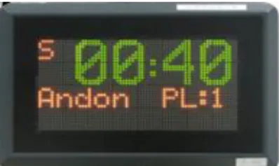
5.5.3.20 Station display board
The station display board provides information about the state of the stations and the tacting time.
38
For example, if the Andon button has been pressed in the station 1:01, the station display board will display an Andon message with the name of the station that needs Andon support. In case the problem cannot be solved at the station before the tacting time has gone and the product has not been rejected, the station display board will erase the Andon message and display a Stop message with name of the station that is generating stop in the production line. The display board will count up and display the stop time while the station has been stopped. The stop time will be reset when the state of the production line becomes okay. Figure 30 illustrates the simulated station display board in this thesis.
Figure 30: Station board display 5.5.3.21 Event control panel
From the event control panel the user can control the state of the stations. The tags used on WinCC are directly connected to PLC variables and are manipulated via buttons and VBScripts. The user can use the buttons to choose what event that is desired on the station. Each station has one button for setting and resetting both Andon and reject. This is a good way to simulate delay and problems with the torque nut runner and the processed product. Figure 31 illustrates the event control panel used in this simulation of DIDRIK.
Figure 31: Event control popup window
5.5.3.22 The torque nut runner
In the production line the torque nut runner communicates with the PLC and DIDRIK via the Profinet I/O and requires previous configuration. In this simulation the simulated torque nut runner communicates with DIDRIK via tags stored in the stations data block. Figure 32 illustrates the torque nut runner used in this simulation.
Like a real torque nut runner, the simulated torque nut runner can be enabled and disabled by WinCC tags linked to PLC variables. An exclamation mark will appear only in case the torque nut runner will be disabled.
39
Figure 32: Torque nut runner from station 1 and 2 disabled
In WinCC, every station has a button with text in Swedish: “dragare” that in English means torque nut runner. This button can be clicked to simulate the action of the torque nut runner. The requirements for the torque nut runner to work are: torque nut runner enable, a new product in the station and a tacting pulse. Without any of them the torque nut runner will not work. The torque nut runner button will change its color from grey to green and the text change from “torque nut runner” to “working” while the torque nut runner is busy doing its job. The torque nut runner will be done after 5 seconds and the text and color will return to their original appearance after the job is done.
Under the torque nut runner there is a button called “status”. Clicking this button will display a pop-up window with information about the state of the torque nut runner. This pop up window contains:
A pillar with four small squares that displays the state of the torque nut runner.
Text that indicates whether the torque nut runner is enabled.
Operation mode:
o Automatic: The nut runner works when it receives orders from a program. o Manual: The nut runner works when the operator presses a button.
Figure 34 shows the appearance of the pillar made for this thesis.
The simulated torque nut runner only works on manual mode, since to the user has to click the torque nut runner button
These states of the torque nut runner are represented by a color and are linked to tags stored in the stations data block, and those are controlled via a function block that simulates the torque nut runner.
The meaning of the colors is described in the Figure 33.
Figure 33: The states of the torque nut runner
When a new product enters the work station, the color of the pillar will become light blue. After this the torque nut runner will wait for the user to click on the torque nut runner button to simulate its action. Some seconds later the colors green and white will light and the runner will be done.
When the button reject from the event control is clicked the pillar will give red light. Figure 34: Torque nut runner pillar made in WinCC illustrates the torque nut runner pillar made in WinCC.
40
Figure 34: Torque nut runner pillar made in WinCC
5.5.4 Login
In DIDRIK one can define different users and groups to control who has permission to do what in the system. There is only one type of login that will allow the user to perform changes in the system.
To log in to the system, the user needs to click on the text field that indicates the current login. A login window will appear and the user can enter username and password. Figure 35 shows the login popup window.
Figure 35: Login popup window
Other types of users that are defined in the system are:
Operators Production managers Production engineers Processors Planners Maintenance
5.5.5 User archive
The WinCC User Archives is a user configurable database system. Data from technical processes can be stored continuously on a server PC via the User Archives of WinCC. In the Graphics Designer, an OLE Control can be configured to display the online data from the User Archives in table form during runtime.
The name of the user archive that is utilized in this demo is Takt1. Data from the current shift will be stored in the user archive. Figure 36 shows the Archive user used in this project. The data to be stored are:
41
Number of processed products
Accumulated stop time
Accumulated tacting time
Planed work time
Number of shifts
Figure 36: Archive user Taktkrets1
42
6 Conclusion
PLC simulation must be used when the experiment or test program in a real system is impossible or impractical to use because of the high costs of prototyping and testing. During test the system can appear weak or unstable and unable to support extensive testing. Experiments in real-time can take a lot of time and are both laborious and expensive.
When simulating, we perform experiments on a model of the real system, rather than the real system itself. By performing simulations and analyzing the results, we can acquire
understanding of how a present system operates, and what would happen if we changed it.
As stated in one of the requirements, this thesis was intended to simulate DIDRIK using a PLC S7-1200 and the TIA portal but the migration of the DIDRIK’s PLC code failed and after many attempts it was decided to finish working with the PLC S7-1200 and the TIA portal.
The goals set out at the start of the project have been reached for the most part using a virtual PLC S7-400 and the SIMATIC STEP 7. The simulation software SIMATIC S7- PLCSIM made it possible to solve the task in an organized way.
One of the goals, that was expressed early in the project, was that all functions from DIDRIK like Andon, reject and tacting would be included in the simulation. In the beginning of the project it was planned to use a real torque nut runner and a real station board display but a real PLC was not available and thus it was not possible to make the torque nut runner and the station board display to work.
The physical station board display was replaced with a picture made in WinCC and some lines of Visual Basic script code. The simulation of the station board display made it possible to display the tacting time, Andon, stop and the stop time.
A function block in the PLC program made it possible to simulate the torque nut runner. This function block also made it possible to visualize the actions of the torque nut runner in the WinCC program.
The elaboration of the DIDRIK programmer’s manual, which also was part of this thesis, was realized during the time the thesis worker was investigating the tasks of all DIDRIK
functions. The manual was written using a SCANIA template for information documents. The purpose of this manual is to provide a description of the PLC code used in the functions of DIDRIK.
Some improvements are still necessary to simulate DIDRIK in a more effective way. The PLC code and the scripts, designed to work with real hardware, must be modified and adapted to work in simulation.
When working with DIDRIK, it is important to have access to good information on how the PLC code for DIDRIK works and how to use it in a way that satisfies the requirements of the projects.
To complete this thesis, employees at SCANIA IT have been very helpful in giving an introduction to DIDRIK and answering questions on difficulties that have appeared.
43
7 References
Printed sources
KTH Campus Telge, Lars Johansson, PLC – programmerings kursbunt, 2008-10-28
DIDRIK
DIDRIK_definition_simplified.pdf, 2013-06-25 Upl402521-DIDRIK_produktifiering.pdf, 2013-06-25
Electronic sources
Wikipedia, SCANIA AB, SCANIA aktiebolag (publ) 2013-09-06
http://en.wikipedia.org/wiki/Scania_AB
Siemens Automation, AS-Interface - Introduction and basics, 2014-05-06
http://www.automation.siemens.com/mcms/industrial-communication/en/support/ik-info/Documents/SYH_asi_grundlagen-76.pdf
Siemens Automation, PROFIBUS introduction, 2013-05-06
https://eb.automation.siemens.com/mall/en/WW/Catalog/Products/10015766?tree=CatalogTr ee
Anybus, PROFINET, 2014-05-06
http://www.anybus.com/technologies/profinet.shtml
IDC-Online, PLC, Introduction to Programmable Logic Controllers, 2013-11-06
http://www.idc-online.com/technical_references/pdfs/instrumentation/IntrotoPLCs.pdf
Odesie, PLC, Programmable Logic Controller, 2013-11-06
http://www.myodesie.com/index.php/wiki/index/returnEntry/id/2962
Matthew Burris, Programmable Logic Controller Overview, 2014-05-06
http://components.about.com/od/Theory/fl/Programmable-Logic-Controller-Overview.htm
Qualys, SCADA security, 2014-05-06
https://media.blackhat.com/bh-ad-11/Sarwate/bh-ad-11-Amol_SCADA_WP.pdf
Siemens Automation, SCADA System SIMATIC WinCC, 2013-10-01
http://www.automation.siemens.com/mcms/human-machine-interface/en/visualization-software/scada/Pages/Default.aspx
Bentek Systems, SCADA, 2013-05-06
http://www.scadalink.com/support/scada.html
Remote monitoring & control, SCADA,2013-05-06
http://www.dpstele.com/dpsnews/techinfo/scada/scada_introduction.php
Siemens Automation, SIMATIC Controller Software, 2013-10-01
http://www.automation.siemens.com/salesmaterial-as/brochure/en/brochure_simatic-industrial-software_en.pdf
44 Siemens Automation, SIMATIC S7-400, 2013-10-01
http://www.automation.siemens.com/mcms/programmable-logic-controller/en/simatic-s7-controller/s7-400/cpu/Pages/Default.aspx
Siemens Automation, Siemens SIMATIC PLC-SIM, 2013-10-04
http://www.automation.siemens.com/mcms/simatic-controller-software/en/step7/simatic-s7-plcsim/pages/default.aspx
Siemens Automation, Step7 Engineering software, 2013-10-04
http://www.automation.siemens.com/mcms/simatic-controller-software/en/step7/pages/default.aspx
Siemens Automation, Step7 Professional, 2013-10-04
http://www.automation.siemens.com/mcms/simatic-controller-software/en/step7/step7-professional/pages/default.aspx
Search enterprise linux,Script, 2014-05-06
http://searchenterpriselinux.techtarget.com/definition/script
Siemens Automation, Siemens TCP/IP driver, 2013-10-04
http://www.kepware.com/Support_Center/SupportDocuments/Help/siemens_tcpip_ethernet.p df
Siemens Automation, Siemens TIA Portal, 2013-10-05
http://www.industry.siemens.com/topics/global/en/tia-portal/controller-sw-tia-portal/Pages/Default.aspx
Siemens Automation, Forum, 2013-08-01 – 2013-10-30
http://support.automation.siemens.com/WW/llisapi.dll?func=cslib.csinfo2&lang=en
Process automation control, Siemens SIMATIC HMI - WinCC v6 Getting Started, 2013-10-04
http://www.pacontrol.com/siemens-simatic-hmi.html
WinCC SBS, WinCC step by step, app on Ipad, 2013-08-01 – 2013-10-30
https://itunes.apple.com/us/app/wincc-sbs/id492276073?mt=8
Siemens Automation, WinCC Scripts, 2013-10-24
http://www.automation.siemens.com/forum/guests/PostShow.aspx?PostID=372012&Languag e=en&PageIndex=1
WinCC connectivity pack, 2013-10-24
45
Appendix I – PLC blocks
Data Block
DB18 – KomP->D>Takt1, data block for monitoring communication from PLC to DIDRIK. DB19– KomD->P>Takt1, data block for monitoring communication from DIDRIK to PLC. DB10 – TaktDB, this DB contains information about:
The process indicator such accumulated work time, accumulated stop time, accumulated number of products, accumulated products, etc.
Number of shifts and their start and stop times.
The first and last station in the tacting block.
Tacting pulse.
Andon signals and reject signals in the tacting block.
DB12 – Takt1, this is an instance data block for FB1010 that contains information about the production time according to the settings of the calendar. This block also stores information from the planned production.
DB80 – DBSetClock, data block that contains variables for setting the clock from WinCC. DB101 – Station 1, data block that contains information about the station 1 such name of the station, done signal, Andon signal , reject signal, torque nut runner, product in, and product. DB102 – Station 2, data block that contains information about the station 2 such name of the station, done signal, Andon signal , reject signal, torque nut runner, product in, and product. DB103 – Station 3, data block that contains information about the station 3 such name of the station, done signal, Andon signal , reject signal, torque nut runner, product in, and product. DB104 – Station 4, data block that contains information about the station 4 such name of the station, done signal, Andon signal , reject signal, torque nut runner, product in, and product. DB177 – LineTakt1, data block that contains information about the enabled torque nut runners in the production line. This data block is also used to generate the product that enters and finally leaves the production line. It is fundamental for the program to know that the product has left the product line otherwise it will be impossible to generate a new product.
Functions
FC1911 - The purpose of this FC is to generate clock pulse through the memory bytes from the PLC.
FC80 - Block for setting PLC’s system clock from WinCC via WinCC tags.
FC10 - A tacting circuit is a sum of a number of stations’ ready signals. Every tacting circuit owns a calendar with which its own tacting time can be generated. In each tacting circuit includes a line board display, tacting time and process indicator.
FC101 - Station 1, consists of the Andon FB1264, the reject FB1266, the stations tact FB 1270 and the torque nut runner FB2013. Apart from the mentioned function calls above, this function contains code that generates a new product when the tact has timed out and all the stations in the production line are okay. If the line is not set to okay, the stop time will be generated and the function should wait until the production line is okay.
FC102 – Station 2, consists of the Andon FB1264, the reject FB1266, the stations tact FB 1270 and the torque nut runner FB2013.
FC103 - Station 3, consists of the Andon FB1264, the reject FB1266, the stations tact FB 1270 and the torque nut runner FB2013
FC104 - Station 4, consists of the Andon FB1264, the reject FB1266, the stations tact FB 1270 and the torque nut runner FB2013. This function verifies whether the product is okay and should leave the production line and set the production to okay. This part of the program helps to generate a new product.
46 Function blocks
FB1010 - This FB controls and plans the production according to the settings of the calendar. This block also generates process indicator and communicates via external DB with the PLC. FB1012 - To calculate the process indicator in the DIDRIK system, it is necessary to input conditions for production in a calendar.
FB1013 - Block to sum and evaluate Andon signals from the station.
FB1117 - Block for calculating the remaining time to turn on and turn off the display board. FB1264 - If the operator has a problem that might cause a stop. She or he will use the Andon-button to alert the Andon for assistance. If the Andon is set, the station will send an alarm message to WinCC, turn on the Andon light, set the Andon variable for history and the Andon variable in the stations DB. The alarm message to WinCC will contain information about the station.
FB1266 - If a problem occurs that cannot be solved at the station, the operator or Andon can choose to reject the product. The rejection will cause the specific product to pass through the line segment without any further work. The activation of the reject signal will occur via the reject button.
FB1270 - This block gathers the signals of the station from Andon, reject, the torque nut runner and the tacting time. It will also check if the job is done before the tacting time has passed. The program opens and copies the content of the station and tacting DBs to temporary variables to verify the clear signals from the station. The station will get a clear sign either if all the signals are clear or if the reject signal has been activated. If the tacting time is over and the station is not clear an alarm message will be send to WinCC.
FB 2013 – This function reads information from three data blocks, tacting DB, previous station DB and current station DB. The tacting DB is necessary to acquire the tacting pulse and allow the action of the torque nut runner.
The previous station DB provides information that helps to control if the previous station has a product ready to be transported to the next station. The program checks if the case is true and writes into the current station DB that a new product has come to the current station and it is ready to be processed.
Further, the function awaits the action signal corresponding to the torque nut runner from WinCC. A timer will run for 5 seconds and then the torque nut runner will be done and disabled until the next tacting pulse. The done signal from the runner is reported to the work station in WinCC and faceplate corresponding to the torque nut runner.
The block communicates with the SCADA system via the I/O variable “Val”, to enable and disable the torque nut runner. The tacting pulse, a new generated product and the torque nut runner signal from WinCC are important in this function block to generate torque. When the job is done the torque nut runner will be disabled. The station DB loads the state of the torque nut runner in the station and it is displayed in the SCADA system. If the job was aborted due to problems with the torque nut runner, this will be disabled. In case that the previous station is empty the current station will be also empty and “hole” will be set in the current station. Organization Block
OB1 - This OB calls FC 101, FC 102, FC 103 and FC 104 that corresponds to the stations, FC1911 for generating pulse and FC80 for setting the system clock.