SSM’s external experts’ review of SKB’s
safety assessment SR-PSU – rock
engineering and concrete barriers
Main review phase
for the expansion of SKB’s final repository for low and intermediate level
waste at Forsmark (SFR) on the 19 December 2014. SSM is tasked with
the review of the application and will issue a statement to the
govern-ment who will decide on the matter. An important part of the
applica-tion is SKB’s assessment of the long-term safety of the repository, which
is documented in the safety analysis named SR-PSU.
Present report compiles results from SSM’s external experts’ reviews of
SR-PSU during the main review phase. The general objective of these
reviews has been to give support to SSM’s assessment of the license
application. More specifically, the instructions to the external experts
have been to make an in depth assessment of the specific issues defined
for the different disciplines.
Project information
Contact person SSM: Georg Lindgren
Contact persons and registration numbers for the different expert review
contributions are given in the report
Table of Contents
1) Review of the evolution of the mechanical stability and hydraulic
conductivity around the rock vaults of SFR
Erik Eberhardt and Mark Diederichs
2) Review of the hydraulic conductivity, sorption, and mechanical
properties of concrete barriers of SFR
2017:31
SSM’s external experts’ review of SKB’s
safety assessment SR-PSU – rock
engineering and concrete barriers
Main review phase
This report concerns a study which has been conducted for the
Swedish Radiation Safety Authority, SSM. The conclusions and
view-points presented in the report are those of the author/authors and
Authors:
Erik Eberhardt, Mark Diederichs
1)1)Fisher Rock Engineering LLC, Radford, VA, USA
Review of the evolution of the
mechanical stability and
hydraulic conductivity around
the rock vaults of SFR
Activity number: 3030014-1026 Registration number: SSM2016-4329 Contact person at SSM: Flavio Lanaro
Abstract
This Report presents the results from a detailed review of the evolution of the mechanical stability and associated hydraulic conductivity around the rock vaults of SKB’s Final Repository for Short-Lived Radioactive Waste (SFR) at Forsmark. The review first examines the relevant parts of SKB’s license application and related analyses concerning the long-term mechanical stability and hydraulic conductivity of the rock mass around the SFR rock vaults. This is discussed in parallel with the findings of SSM’s initial review. A detailed analysis is then presented using the 2-D distinct-element code UDEC to investigate the expected deterioration of the mechanical properties of the intact rock and rock fractures over time, and its effects on the stability of the SFR rock vaults, which in turn may result in changes in the hydraulic conductivity of the near-field rock mass. Both the existing SFR 1 rock vault layout and the proposed SFR 3 rock vault layout were analysed, and each layout was analysed using four Discrete Fracture Network (DFN) realizations to account for spatial variability in the location, intersection and dip angles of critical fractures. Each analysis was carried out for the reference times of 1000, 10,000, 20,000 and 50,000 years, with the latter time periods including simulations of permafrost and permafrost melting, and glacial loading and unloading. It was found that the SKB analysis, reported in SKB R-13-53, was overly conservative in how the strength degradation procedure was implemented (i.e., fracture friction angles were reduced uniformly as a function of distances from the excavation boundary), and that friction angles as low as 5.7 degrees were required to simulate large-scale collapse. This compares to the lowest values we could find in the literature of 8 degrees. SKB R-13-53 found that the height of the loosened rock would not reach the seabed, from which the SKB Safety Analysis for SFR (SKB TR-14-01) concludes that there should be no risk of a direct connection between the rock vaults and the seabed.
The UDEC analysis presented in this Report reaches a similar conclusion. The UDEC models employ a time-dependent strength degradation procedure based on extrapolated data from long-term testing of granitic rock, and implemented using functions that account for dependencies on the driving differential stress (or shear stress in the case of fractures) and the confinement (or normal stress). In contrast to the analysis reported in SKB R-13-53, our analysis considers both strength
degradation of the intact blocks and along the fractures. However, it is also conservative as it assumes full fracture persistence and assumes 2-D plane strain conditions for block stability and movement.
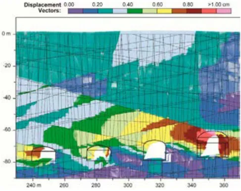
The UDEC results for SFR 1 suggest that over the full time and climate based scenarios modelled, that instabilities will likely not evolve beyond minor roof failures (isolated wedges) and limited, localized spalling and structural shear. The latter (i.e., structural shear and dilation of fractures), may however evolve to include a 40% increase in the cumulative fracture apertures in the near-field surrounding the rock vaults, and up to a 300% increase within a 1 m zone of the individual rock vaults. Assuming a cubic law relationship for fracture permeability, this
approximates as a 2.7 (40%) to 64 (300%) times increase, respectively, of the rock mass permeability. For the SFR 3 case, the combination of greater depth and increased number of larger non-backfilled excavations (3 of 4 excavations backfilled in SFR-1 versus only 2 of 6 in SFR-3), resulted in a significant increase in rock mass damage above and around the excavations. For the permafrost and permafrost melting scenario, several instabilities were seen to initiate involving block movements enabled by the removal of the permafrost-enhanced fracture strength (i.e., cohesive ice) together with the normal stresses acting on the fractures relaxing
in response to ice pressures returning to their hydrostatic levels upon melting. However, only one of these DFN realizations evolved into a partial collapse, with a stable arch subsequently re-establishing. Ultimately, failure in this case was due to the combination of fracture orientations and intersections specific to the DFN realization as the same failure did not develop in the other three DFN realizations. For the glacial loading and unloading scenario, significant rock mass spalling and block failures were observed for the SFR 3 models, most notably in the non-backfilled BLA-type rock vaults. During the start of glacial loading, there is a phase of stress relaxation (due to crustal flexure) followed by horizontal and vertical compression. This cycle creates significant rock mass damage and the stress conditions for accelerated time-dependent strength degradation. Subsequent glacial unloading, restoration of the pre-glacial stress state and permafrost melting then allows this damaged rock to destabilize further, creating more significant failures and limited collapse. In the worst cases, spalling and failure extends up to 20 m above the roof, although runaway collapse beyond the upper bounding deformation zones does not occur. The effects of this increased block instability on the
cumulative fracture aperture and fracture permeability of the near-field rock mass around the SFR 3 rock vaults was similar to that in SFR 1. However, for the SFR 3 case, the EDZ was seen to evolve more deeply and extend across the full width of the rock vaults, especially above the non-backfilled BLA-type rock vaults. In several cases, the EDZ interacts with intersecting sub-vertical fractures and propagates several metres upwards towards the overlying deformation zone, amplifying the extent of the EDZ during glacial loading and unloading. Based on relationships in the published literature, this could drive the local intact rock permeability up to 2 to 3 orders of magnitude higher within these damage zones.
Contents
1. Introduction ... 5
2. Review of Relevant SKB Analyses ... 7
2.1. SKB TR-14-01 and R-13-53 ... 7
2.1.1. Authors’ Review Considerations ... 10
2.2. SSM Initial Review ... 11
3. Independent Scoping Analyses ... 14
3.1. Requirements and Allowances ... 14
3.2. Numerical Method and Software Used ... 16
3.3. UDEC Model Development ... 17
3.3.1. Model Geometry for SFR 1 and 3 ... 17
3.3.2. Geology and Deformation Zones ... 19
3.3.3. Discrete Fracture Network (DFN) ... 23
3.3.4. Model Discretization and Meshing ... 28
3.3.5. Rock Mass and Discontinuity Properties ... 28
3.3.6. In Situ Stress and Boundary Conditions ... 30
3.3.7. Groundwater Conditions ... 32
3.3.8. Rock Reinforcement and Backfill Material ... 34
3.4. Modelling Procedure for Long-Term Behaviour ... 36
3.4.1. Long-Term Strength Degradation Formulation ... 36
3.4.2. Long-Term Strength Degradation Implementation ... 43
3.5. Modelling of Permafrost (Year 20,000) ... 45
3.6. Modelling of Glacial Loading (Year 50,000) ... 46
4. Analysis Results ... 50
4.1. Stability ... 50
4.1.1. Year 50 - Construction and Backfilling ... 50
4.1.2. Year 1000 and 10,000 - Strength Degradation ... 57
4.1.3. Year 20,000 – Permafrost and Permafrost Melting ... 63
4.1.4. Year 50,000 to 66,000 – Glacial Loading and Unloading. 65 4.1.5. Backfill Loading ... 73
4.1.6. Hydraulic Conductivity Changes ... 74
5. Conclusions ... 83 6. References ... 87 APPENDIX 1 ... 89 APPENDIX 2 ... 91 APPENDIX 3 ... 177 APPENDIX 4 ... 263
1. Introduction
This Report presents the findings of a detailed review of the evolution of the mechanical stability and associated hydraulic conductivity around the rock vaults of SKB’s Final Repository for Short-Lived Radioactive Waste (SFR) at Forsmark. This follows SSM’s initial review phase completed in 2016 regarding SKB’s application to expand the SFR. SKB’s analysis of the long-term safety for the extension is documented in the safety assessment named SR-PSU (SKB TR-14-01). The initial SSM review included three reports covering different aspects of the SKB
assessment. These examined:
the hydrogeological and chemical aspects (SSM 2016:08) the radionuclide transport, dose assessment, and safety analysis
methodology (SSM 2016:09)
the engineered barriers, engineering geology and chemical inventory (SSM 2016:12)
SSM is now conducting their main review phase and this Report describes the findings of an in-depth analysis that builds on the following objective:
To evaluate SKB’s understanding of the evolution of the mechanical stability and hydraulic conductivity of the rock mass around the rock caverns after closure with respect to its implications on the long-term safety of the SFR repository.
This recognizes that the stability of the rock vaults and associated changes in the hydraulic conductivity of the rock mass are important factors for achieving the safety requirement of limiting the groundwater flow into the rock vaults containing the waste.
The review reported here first examines the relevant parts of SKB’s license application and related analyses concerning the long-term mechanical stability and hydraulic conductivity of the rock mass around the SFR vaults. This is discussed in parallel with the findings of SSM’s initial review. Next, a series of scoping calculations are reported that investigate the expected deterioration of the mechanical properties of the rock and rock fractures over the long time periods involved, and its effects on the stability of the rock vaults, which in turn may result in changes in the hydraulic conductivity of the rock mass in the near-field of the SFR rooms. The consequence of such changes on the localisation of groundwater flow is of concern to SSM. To address these concerns, the analyses were directed to address several specific questions posed by SSM, which focus on:
The appropriateness and uncertainty of the degraded and residual mechanical properties of the rock fractures as assumed in SKB R-13-53. This includes estimates of the points in time when the degraded and residual values of the mechanical properties of the rock fractures assumed in SKB R-13-53 could be reached after closure of the repository.
The initial stability of the pillars between the rock vaults, and its evolution due to loads and degradation of the rock mass properties at different points
in time, specifically at 1000, 10,000, 20,000 and 50,000 years after closure of the repository, with the simulation of permafrost and permafrost melting at Year 20,000 and glacial loading and unloading at Year 50,000. This will be carried out through a series of advanced 2-D numerical models
employing a hydro-mechanical coupling to account for the influence of pore pressures on the effective stresses. The treatment of fluid flow is outside the scope of the analyses and not considered. Results will be used to estimate changes in the hydraulic conductivity of the near-field rock mass surrounding the vaults arising from the strength degradation and any modelled instabilities.
The effect of the supporting function of rock reinforcements in the rock vaults and their deterioration after closure of the repository.
This Report concludes with recommendations on the suitability of the rock vault design proposed by SKB, based on scoping calculations that study the potential of significant risk of instability after closure of the repository. Where necessary, suggestions for requests of complementary information to SKB and its extension are provided.
2. Review of Relevant SKB Analyses
2.1. SKB TR-14-01 and R-13-53
SKB TR-14-01 presents the main reporting of the long-term safety assessment, SR-PSU, for the SFR repository for short-lived low- and intermediate-level radioactive wastes located in Forsmark. The assessment is based on plans to extend the existing facility, SFR 1, to include additional rock vaults for decommissioning waste as part of a SFR 3 (Figure 1). The review presented here only pertains to the sections of SKB TR-14-01 and associated documents concerning the long-term mechanical stability and hydraulic conductivity of the rock mass around the SFR 1 and 3 vaults.
Figure 1: The existing SFR facility at Forsmark, SFR 1 (light grey), and extension, SFR 3
(blue), with access tunnels. From SKB TR-14-01.
The safety assessment SR-PSU builds on the assessment for SFR 1 (SKB R-08-130), and evaluates the safety of the repository over a period of 100,000 years. SKB R-13-53 (referenced as Mas Ivars et al., 2014) is cited as the basis for the assessment of long-term mechanical stability of the SFR 1 and 3 vaults. This report is similarly referenced in the Geosphere process report, SKB TR-14-05, which serves as the supporting document for SKB TR-14-01 with respect to describing the influence of geosphere processes on the long-term safety of the repository.
In SKB R-13-53, the commercial 3-D distinct-element program 3DEC was used to model the 1BMA and 1BLA vaults (3DEC is the 3-D version of the 2-D program UDEC used in the present Report, as described in later sections). Two objectives are cited for SKB R-13-53: i) to analyse if there is a risk of loosening of the rock mass through displacements into the vaults that can lead to collapse up to the surface and breaching of the sea bed; and ii) if there is a risk of instability in the pillars between the vaults. The analyses are conducted without considering the influence of groundwater and water pressures in the fractures.
The analysis in SKB R-13-53 first assesses the question of excavation and pillar stability by analyzing eight different Discrete Fracture Network (DFN) realizations
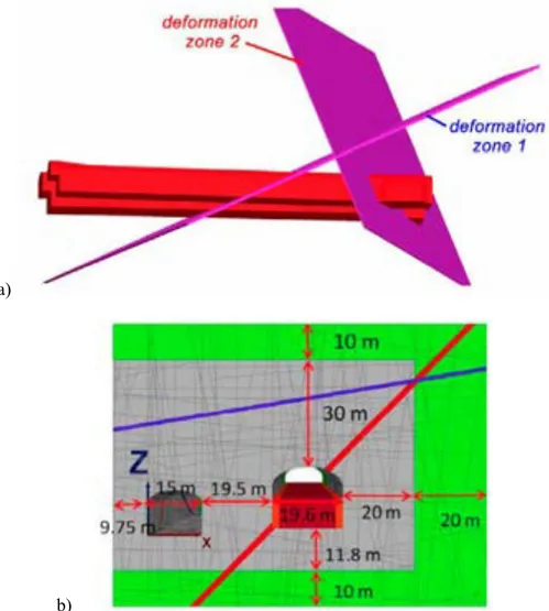
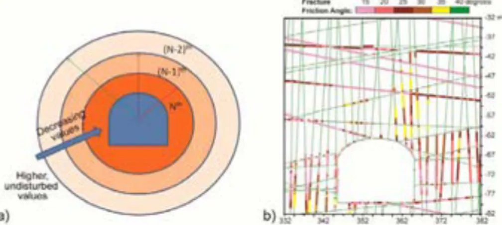
based on the average orientations of the different joint sets and their standard deviations mapped during construction of SFR 1 (taken from SKB SFR-87-03). A different fracture random generator is used for each DFN case. All discontinuities are modelled as being perfectly planar, infinite structures, which is correctly considered to be conservative. The blocks were modelled as being deformable employing a Mohr-Coulomb elasto-plastic constitutive model and the discontinuities were modelled employing a Coulomb slip model. The presence of two distinct deformation zones was also modelled. Representative material properties for the intact rock and discontinuities were based on those reported in SKB R-07-06, which in turn are based on the modelling of the Singö deformation zone. The Singö is a regional deformation zone with a length of 30 km and width between 53 and 200 m (SKB R-07-45, p. 160). A review of SKB R-07-06 indicates that these values are not based on site specific testing but involve estimates derived from values taken from the literature and empirical relationships. The set of values used in SKB R-13-53 are those reported as transition values between those for the host rock and core of the Singö deformation zone (Figure 2). The in situ stress state was based on values reported in a preliminary report for a proposed final repository for spent nuclear fuel at Forsmark (SKB R-02-32).
Figure 2: Schematic illustration of the transition zone associated with brittle deformation zones
observed at Forsmark such as the Singö deformation zone. From SKB R-14-17.
The results of this analysis indicate that the excavations are stable, even without rock reinforcement and with fracture properties for the worst case scenario of zero cohesion and 15 degree friction angle. The authors note that in addition to the modelling of eight different DFN realizations, the models encompass 100 meters of length of each vault, thus incorporating with good certainty the most adverse block configurations possible. For block instabilities to arise, unreasonably low residual friction angles between 5.7 and 8.7 degrees are required. The authors compare this to the absolute lowest value of 8 degrees they could find through a literature review they conducted.
SKB TR-14-01 reports the findings based on the lower friction angle value of 5.7 degrees, and its subsequent use in a rigid block analysis performed in SKB R-13-53 to model the collapse of blocks into the 1BLA and 1BMA rock vaults. The results of this analysis suggest that in the event of collapse due to long-term strength
degradation (leading to fracture strengths of zero cohesion and friction angles of 5.7 degrees), the height of the loosed rock would reach 34 m above the roof of the vaults
and then form a stable arch. This would leave approximately 26 m of cover between the collapse and seabed, from which SKB TR-14-01 draws the conclusion that there should be no risk of a direct connection between the vaults and the seabed.
Notably, the analysis in SKB R-13-53 does not consider the effects of permafrost or glacial loading. The Geosphere report (SKB TR-14-05, p. 84) suggests that the expected thermo-mechanical effects on groundwater flow modelling during the periglacial and glacial periods are insignificant, but this statement does not include mechanical stability. The climate cases for the SR-PSU safety assessment (SKB TR-13-05) indicates that permafrost is expected to develop at Forsmark in three of the four climate cases considered. However, only one of these, the Weichselian glacial cycle, includes significant permafrost within the 50,000 year time interval
considered for the independent stability analyses presented later in this Report. A permafrost depth of 75-100 m between 25,000 and 35,000 years from present is indicated (Figure 3). These depths would reach the SFR 1 repository level, but not the SFR 3 extension. The Weichselian climate case predicts the maximum depth of permafrost extending to approximately 200-250 m after 50,000 years, which would reach the SFR 3 extension. An exception regarding the other climate cases is raised for the “early periglacial climate case”. SKB TR-13-04 (p. 65) concludes that based on the assumptions made for the permafrost modelling, frozen ground down to the SFR 1 depth (and approaching the SFR 3 depth) cannot be excluded at 17,000 years.
Figure 3: Modelled permafrost and perennially frozen ground depths at Forsmark for the SKB
Weichselian glacial cycle climate case. From SKB TR-13-05.
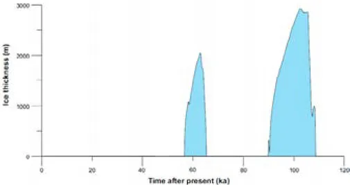
SKB TR-14-01 (p. 19) suggests that the current Holocene interglacial will be considerably longer than previous interglacials and that the onset of the next glaciation will not occur in the next 50,000 years, or perhaps not even in the next 100,000 years. The glacial climate domain is therefore not included in the reference evolution. The Climate report (SKB TR-13-05, p. 175-178) does include one climate case, the Weichselian glacial cycle, that includes the Forsmark area being covered by glacial ice in the next 100,000 years. Reference is made to a maximum ice-sheet thickness over Forsmark of approximately 2000 m after 60,000 years from present and 2900 m at around 100,000 years (Figure 4). SKB TR-13-05 explains that any scenario involving glacial ice above the SFR repository, and the associated increase in groundwater flux, is covered by cases in the safety assessments in SR-PSU that assume complete degradation of the concrete containment structures and no
and then form a stable arch. This would leave approximately 26 m of cover between the collapse and seabed, from which SKB TR-14-01 draws the conclusion that there should be no risk of a direct connection between the vaults and the seabed.
Notably, the analysis in SKB R-13-53 does not consider the effects of permafrost or glacial loading. The Geosphere report (SKB TR-14-05, p. 84) suggests that the expected thermo-mechanical effects on groundwater flow modelling during the periglacial and glacial periods are insignificant, but this statement does not include mechanical stability. The climate cases for the SR-PSU safety assessment (SKB TR-13-05) indicates that permafrost is expected to develop at Forsmark in three of the four climate cases considered. However, only one of these, the Weichselian glacial cycle, includes significant permafrost within the 50,000 year time interval
considered for the independent stability analyses presented later in this Report. A permafrost depth of 75-100 m between 25,000 and 35,000 years from present is indicated (Figure 3). These depths would reach the SFR 1 repository level, but not the SFR 3 extension. The Weichselian climate case predicts the maximum depth of permafrost extending to approximately 200-250 m after 50,000 years, which would reach the SFR 3 extension. An exception regarding the other climate cases is raised for the “early periglacial climate case”. SKB TR-13-04 (p. 65) concludes that based on the assumptions made for the permafrost modelling, frozen ground down to the SFR 1 depth (and approaching the SFR 3 depth) cannot be excluded at 17,000 years.
Figure 3: Modelled permafrost and perennially frozen ground depths at Forsmark for the SKB
Weichselian glacial cycle climate case. From SKB TR-13-05.
SKB TR-14-01 (p. 19) suggests that the current Holocene interglacial will be considerably longer than previous interglacials and that the onset of the next glaciation will not occur in the next 50,000 years, or perhaps not even in the next 100,000 years. The glacial climate domain is therefore not included in the reference evolution. The Climate report (SKB TR-13-05, p. 175-178) does include one climate case, the Weichselian glacial cycle, that includes the Forsmark area being covered by glacial ice in the next 100,000 years. Reference is made to a maximum ice-sheet thickness over Forsmark of approximately 2000 m after 60,000 years from present and 2900 m at around 100,000 years (Figure 4). SKB TR-13-05 explains that any scenario involving glacial ice above the SFR repository, and the associated increase in groundwater flux, is covered by cases in the safety assessments in SR-PSU that assume complete degradation of the concrete containment structures and no
geosphere retention. SKB TR-14-01 reports that loss of barrier function and/or high water flow in the repository is considered to be a low likelihood to residual scenario (i.e., sequences of events illustrating the significance of individual barriers and barrier functions), which when combined, exceed SSM risk criteria (regulation SSMFS 2008:37) for peak dose exposure limits for groups but are less than limits for individual exposure.
Figure 4: Modelled ice-sheet thickness at the Forsmark site for the SKB Weichselian glacial
cycle climate case. From SKB TR-13-05.
2.1.1. Authors’ Review Considerations
A note regarding the conclusions in SKB R-13-53 suggesting that any potential failure of the rock vaults will be limited and should be of no risk in directly connecting the vaults and the seabed, this assumes that unravelling will not occur along the steeply dipping deformation zone that intersects the roof of 1BMA. Caving along such features has been seen to form collapse structures above shallow tunnels that reach surface (e.g., Nilsen, 1994). However, as demonstrated in SKB R-13-53, the bulking of the failed material often arrests void migration. SKB TR-14-01 (p. 147) also refers to “no risk” of breach of the seabed, but at least in the
assessment presented regarding the mechanical evolution, only discusses the likelihood of the event occurring but not the consequences of a direct conduit between the sea floor and rock vaults. It is therefore not clear if the assessment of risk properly considers both the likelihood and consequences.
Concerning the effects of a glacial cycle (including permafrost) on the repository safety, the independent analysis conducted for this Report will be carried out from construction of the repository up to and including a nominal 66,000 year case. This includes simulations that account for both the loading and unloading effects related to permafrost and glaciation. For the permafrost assumption, this will consider the early periglacial case in SKB TR-13-05, in which permafrost down to the repository level is considered a possibility between 17,500 and 20,500 years from present. Permafrost melting is assumed to occur within 1000 years. For the glacial cycle assumption, the peak glaciation at 60,000 years from the Weichselian climate case will be used for this. Glacially induced stresses will be applied following the logic outlined in SKB TR-09-15 with some modifications to account for near-field conditions in the upper few hundred metres of the crust. Deglaciation based on this climate case is assumed to occur within 2500 years.
2.2. SSM Initial Review
SSM’s initial review phase included several external expert reviews of SKB’s safety assessment in SR-PSU, as previously noted. Of specific relevance to the detailed analysis reported here are the reviews of the hydrogeological and engineering geology models.
The review of the hydrogeological models discussed in SSM 2016:08 includes an examination of the structural geological model and treatment of deformation zones and natural fractures (derived from SKB TR-11-04) used as the basis for the hydrogeological models used for the SR-PSU safety assessment (SKB TR-14-01). The review points to the quantitative treatment of the fracture mapping data obtained during construction of SFR 1 (reported in SKB SFR 87-03, and cited as
Christiansson & Bolvede, 1987), as being limited and including size bias (SSM 2016:08, Part 1, p. 22). The same data is used to generate the DFNs used in SKB R-13-53 and the analyses conducted for this review. However, because both of these assume the conservative case of fully persistent discontinuities (relative to the mechanical stability of the excavated rock vaults), the issue of size bias is not applicable here. SSM 2016:08 Parts 1 and 2 also both point to a lack of consideration given to the treatment of heterogeneity as a function of depth and structural domains. This same point is raised in SSM 2016:12, Part 3, regarding the site description of the SFR area used in the SKB TR-14-01 safety assessment. SKB R-13-53 reports the presence of three joint sets mapped in the excavation roof and walls of SFR 1, and reports the orientations with standard deviations and average spacings for each of these sets. These are uniformly applied through the model domains in the stability analyses conducted (both in SKB R-13-53 and here), and is acknowledged here as a key uncertainty. SSM 2016:08 provides further suggestions regarding parametrization of the hydraulic domains and flow connectivity of transmissive fractures. Although these are important considerations, the scope of the independent analyses presented in this Report is limited to the consideration of pore pressures and effective stresses, but not flow.
SSM 2016:12, Part 3, which reviews the engineering geology aspects of SR-PSU, provides several important comments relevant to the stability of the rock vaults. First, it is noted that no new data was collected regarding the rock mass properties and characteristics specific to SFR 3 (SSM 2016:12, Part 3, p. 13). Instead, the data used pertains to old data collected during construction of SFR 1. This same data was used in the stability analyses reported in SKB R-13-53, and by default, in the stability analyses presented in this Report. A related oversight identified in SSM 2016:12, Part 3 (p. 48), is that the in situ stress input used for the long-term stability analysis in SKB R-13-53 appears to be based on an older interpretation of the in situ stress measurement data reported in SKB R-02-32. The estimated trends for the SFR 1 were later updated in SKB TR-11-04. The SKB TR-11-04 stress field was used for the independent analyses carried out as part of this Report, and is discussed in more detail in the description of the numerical models developed.
Second, it is noted that the stability analyses in SKB R-13-53 is limited to two rock vaults, 1BMA and 1BLA, in the existing SFR 1 (SSM 2016:12, Part 3, p. 13, 47-48); no analyses are provided specific to SFR 3. Accordingly, the independent stability analyses presented in this Report includes the consideration of all five rock vaults in SFR 1, as well as a comparative analysis that includes all six rock vaults associated with the planned layout of SFR 3. Reference is also made in SSM 2016:12, Part 3 to the need for a renewed stability analysis of the existing silo in SFR 1 given its importance to the long-term safety of the completed SFR and its large size. Because
the scope of the analyses requested as part of this review was limited to
two-dimensional modelling, the long-term stability of the silo is also not considered here. Another important comment was that no attempt at using monitoring data collected during construction of SFR 1 was made to calibrate the stability analyses reported in SKB R-13-53. SSM 2016:12, Part 3 (p. 14) correctly notes that such data is
routinely collected in tunnel construction and SKB should be in a good position to use/provide monitoring data to calibrate and validate the numerical results.
Reporting of the experiences during construction of SFR 1 is provided in SKB R-07-10 and R-14-17. SKB R-07-R-07-10 (p. 75-76) describes the deformation monitoring conducted during construction, which involved the use of extensometers and focussed on the Singö deformation zone and the silo. These report total deformation values on the order of 1 mm. No deformation data is reported in association with the construction and performance of the rock vaults. SKB R-07-10 (p. 79) concludes with the observation that no stability or other rock engineering problems had been identified after the commissioning of the SFR. The only exception was in relation to the Forsmark Plant and the discharge tunnel for cooling water from Reactor #3 (“Forsmark 3 tunnel”), which experienced a rock fall within the Singö deformation zone across a 10-20 m section of the tunnel (Figure 5).
Figure 5: Photo and sketch of the overbreak experienced above the Forsmark 3 tunnel after
intersecting the Singö deformation zone. From SKB R-07-10.
SSM 2016:12, Part 3 (p. 14-15) also notes that the stability analysis reported in SKB R-13-53 was conducted without consideration of pore pressures within the existing natural fractures and their effect on the effective normal stresses and deterioration of frictional strength properties of the fractures. SSM 2016:12, Part 3 emphasizes that analyses of the rock mass response to excavation and strength degradation over time should include an accounting of the ground water pressures around the rock caverns. It is noted here that the lower bound friction angles assumed in SKB R-13-53 are exceptionally low regardless of the absence of pore pressures in the analyses. A discussion of these properties as well as the inclusion of pore pressures in the independent analyses conducted in this Report, is presented in later sections of the report. SSM 2016:12, Part 3 also discusses the absence of earthquake loading in the SKB stability analyses and recommends this be undertaken. Earthquake loading wasn’t included in the scope of the independent analyses performed here.
In summarizing the suggested topics for more detailed review, SSM 2016:12, Part 3 (pp. 59-64) suggests in order of priority:
Long-term stability of SFR rock vaults and the impact of climate changes and future glaciations.
Effect of earthquakes on nearby faults and the stability of SFR caverns. Systematic methodology for rock mass property determination.
Effect of rock support degradation on the long-term performance of SFR. Suitability of the location of the SFR extension.
The independent analyses presented in the next section addresses several of these. Included is consideration of the impact of climate change and future glaciations in the form of simulated permafrost to the repository depth and glacial loading, followed by glacial unloading and permafrost melting, as indicated in Figure 3 and Figure 4. The effect of rock support degradation over time and evaluation of the SFR 3 layout is also included. Not considered within the scope of the present review assignment was the effect of earthquakes and systematic determination of rock mass properties. Because the natural fractures present in the rock were modelled in the near-field explicitly at a 1:1 spacing in this Report, the use of intact rock properties was assumed to be acceptable. However, as previously noted, the effects of size bias in the fracture mapping data limiting the consideration of smaller fractures in the DFNs embedded in the analyses may warrant some scaling of the intact rock properties used to account for the weakening effects of smaller fractures.
3. Independent Scoping Analyses
3.1. Requirements and Allowances
The requirements and allowances for the numerical analyses as specified by SSM for this review assignment are summarized below. Included with these are details describing the actions taken, and any deviations from the allowances provided where it was decided that the models could be improved.
Specification: 2-D model scoping calculations of the mechanical stability and hydraulic conductivity of the rock mass around the rock vaults should be done considering one typical section of the existing SFR 1 (e.g. the rock pillar between 1BMA and 1BLA) and one typical section of the SFR 3 extension. The advantage of a symmetrical section could be exploited.
Action: Because the 2-D models are not overly demanding with respect to
computational requirements, it was decided that the SFR 1 models should include the rock vaults adjacent to 1BMA and 1BLA (i.e., 1BTF and 2BTF). Symmetry for model simplification was not necessary. Similarly, the models for the SFR 3 extension were developed to include the full rock vault layout (i.e., 2BMA, 5BLA, 4BLA, 3BLA, 2BLA and1BRT). Specification: The modelling of rock reinforcements of the rock vaults is
not required.
Action: Rock reinforcements were not explicitly modelled in the analyses.
However, their influence on limiting block movements during excavation of the rock vaults was implicitly included. This was deemed necessary given the conservative joint friction values adopted. It was assumed that any rock reinforcement (shotcrete, rockbolts, etc.) would be fully degraded and non-functioning after 100 years. Thus, the stabilizing influence of reinforcement added during excavation of the rock vaults was subsequently removed at Year 100 in the models.
Specification: 2-D modelling should be carried out with a numerical code that can explicitly describe Discrete Fracture Networks (DFN) and rock fracture deformability. The adopted numerical code for the calculations must be chosen among available codes that have been extensively validated, verified, well documented and quality assured.
Action: The 2-D distinct-element code UDEC v. 6.00.322 (Itasca, 2016)
was used for this assignment. The code meets the requirements specified, as described in detail in subsequent sections of this Report.
Specification: Input parameters for the rock and fractures should be compatible with assumptions in SKB R-13-53, and considering the review comments from SSM’s initial review phase contained in SSM Report 2016:12, Part 3.
Action: Unless otherwise noted, input parameters were based on those
reported in SKB R-13-53. Where incompatibilities have been identified in SSM 2016:12 Part 3, for example reporting that outdated data for the in situ stress input was used in the stability analyses reported in SKB R-13-53, the relevant input parameters were vetted accordingly. Where required input parameters not specified in SKB R-13-53 or provided as singular values where a range might be more appropriate to bound the uncertainty, values were based on those reported in SKB TR-14-01 (e.g. rock mass density) or
in SKB R-07-31 (referenced as Glamheden et al, 2007), where a more thorough treatment of the site characteristics are reported. The input parameters used in the analyses together with explanations as to their sources are discussed in detail in the description of the model development.
Specification: The effect of groundwater pressure on the stability of the
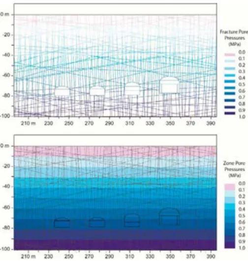
rock caverns should be explicitly evaluated (as suggested in SSM Report 2016:12, Part 3, sec. 3.9.5). However, no groundwater flow calculations are required. The regional flow at Forsmark occurs mainly parallel to the long axis of the rock caverns. A comment about the relation between the hydraulic conductivity of the undisturbed rock mass to its value after excavation of the vaults should be provided.
Action: It was assumed that the near-field groundwater flow is parallel to
the rock vaults, and therefore perpendicular to the 2-D section modelled. As such, the total pore pressure head was treated as static with pore pressures equal to pressure head equal to sea level. Effective stresses were used for matrix and water pressures applied to joints, but these were not fully coupled given the time frames considered where excess over/under pressures would dissipate quickly (relative to 1000 or 10,000 years). In the short-term construction phase, it can be assumed that mean apertures of at least one joint set will increase towards the excavation boundary leading to a short-term state that is more stable (higher effective normal pressure) than the longer term saturated state. Thus, the saturated state was considered to be critical.
Specification: The reference points in times (1000, 10,000, 20,000 and
50,000 years) should highlight the deterioration of the rock and fracture properties and the changes of the loading conditions (e.g., permafrost at Year 20,000, and glacial loading at Year 50,000).
Action: The reference times were modelled as specified, with the 20,000
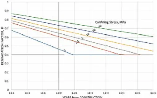
year model simulating the effects of permafrost, and the 50,000 year model simulating glacial loading. These were considered via two separate scenarios. The first modelled permafrost at Year 20,000 followed by permafrost melting at Year 21,000. Separately, the Year 20,000 permafrost model was extended to consider glacial loading at Year 50,000 followed by glacial unloading and then permafrost melting. Rock and joint strength degradation rates were based on existing data-driven models for granitic rock accounting for such time-dependent factors as subcritical crack growth. It was assumed that due to the already conservative frictional values adopted in SKB R-13-53 that friction will not modify over the specified time periods but that cohesion from joint asperities will degrade at the same rates as those extrapolated from published long-term tests on intact granite. Permafrost has the effect of increasing joint cohesion but also joint aperture. The rates of freezing advance in permafrost at depth are assumed to be low such that excess pore pressure can dissipate and fracture expansion is limited although the impact of a 10% pressure increase in the fractures was explored (to correspond to expansion during static freezing). In the latter time period, this expansion was combined with elevated pore pressure assumptions due to glaciation. Glacial loading was simulated using current models of vertical boundary load increase and associated Poisson ratio effects as well as increments of load from crustal flexure. These will be based on the peak glaciation at 60,000 years from the Weichselian climate case described in SKB TR-09-15.
in SKB R-07-31 (referenced as Glamheden et al, 2007), where a more thorough treatment of the site characteristics are reported. The input parameters used in the analyses together with explanations as to their sources are discussed in detail in the description of the model development.
Specification: The effect of groundwater pressure on the stability of the
rock caverns should be explicitly evaluated (as suggested in SSM Report 2016:12, Part 3, sec. 3.9.5). However, no groundwater flow calculations are required. The regional flow at Forsmark occurs mainly parallel to the long axis of the rock caverns. A comment about the relation between the hydraulic conductivity of the undisturbed rock mass to its value after excavation of the vaults should be provided.
Action: It was assumed that the near-field groundwater flow is parallel to
the rock vaults, and therefore perpendicular to the 2-D section modelled. As such, the total pore pressure head was treated as static with pore pressures equal to pressure head equal to sea level. Effective stresses were used for matrix and water pressures applied to joints, but these were not fully coupled given the time frames considered where excess over/under pressures would dissipate quickly (relative to 1000 or 10,000 years). In the short-term construction phase, it can be assumed that mean apertures of at least one joint set will increase towards the excavation boundary leading to a short-term state that is more stable (higher effective normal pressure) than the longer term saturated state. Thus, the saturated state was considered to be critical.
Specification: The reference points in times (1000, 10,000, 20,000 and
50,000 years) should highlight the deterioration of the rock and fracture properties and the changes of the loading conditions (e.g., permafrost at Year 20,000, and glacial loading at Year 50,000).
Action: The reference times were modelled as specified, with the 20,000
year model simulating the effects of permafrost, and the 50,000 year model simulating glacial loading. These were considered via two separate scenarios. The first modelled permafrost at Year 20,000 followed by permafrost melting at Year 21,000. Separately, the Year 20,000 permafrost model was extended to consider glacial loading at Year 50,000 followed by glacial unloading and then permafrost melting. Rock and joint strength degradation rates were based on existing data-driven models for granitic rock accounting for such time-dependent factors as subcritical crack growth. It was assumed that due to the already conservative frictional values adopted in SKB R-13-53 that friction will not modify over the specified time periods but that cohesion from joint asperities will degrade at the same rates as those extrapolated from published long-term tests on intact granite. Permafrost has the effect of increasing joint cohesion but also joint aperture. The rates of freezing advance in permafrost at depth are assumed to be low such that excess pore pressure can dissipate and fracture expansion is limited although the impact of a 10% pressure increase in the fractures was explored (to correspond to expansion during static freezing). In the latter time period, this expansion was combined with elevated pore pressure assumptions due to glaciation. Glacial loading was simulated using current models of vertical boundary load increase and associated Poisson ratio effects as well as increments of load from crustal flexure. These will be based on the peak glaciation at 60,000 years from the Weichselian climate case described in SKB TR-09-15.
Specifications: Quantify loads on the concrete barriers of the repository if stability of the rock vaults change over time.
Action: The UDEC model was developed to include the concrete barriers
and backfill as described in SKB R-13-53 and TR-14-01. History points were included to track the stresses that develop in these.
3.2. Numerical Method and Software Used
Selection of the numerical modelling software used was restricted to commercially available codes that have been extensively validated, verified, well documented and quality assured. Preference was given to a numerical method and program capable of explicitly modelling a Discrete Fracture Network (DFN) and associated rock fracture deformability. Based on these, the 2-D distinct-element code UDEC (version 6.0) was selected. UDEC is developed and distributed by Itasca
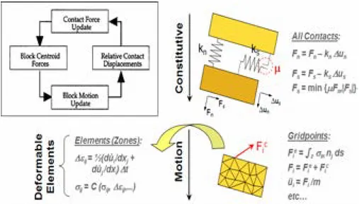
International (Itasca, 2016), and has been extensively used in the rock engineering community and features prominently in the published scientific and technical literature. The analyses in SKB R-13-53 was performed using 3DEC, the 3-D version of UDEC. The capabilities of UDEC and its verification are fully documented in its user manual (Itasca, 2016). These are summarized below. UDEC models a rock mass as an assemblage of discrete, deformable blocks defined by a DFN model. Discontinuities are generated as interconnected planar features. The relative movement along these contacts is governed by linear or non-linear force-displacement relations for movement in both shear and normal directions. Numerical contacts are comprised of corner-to-corner, corner, and edge-to-edge contacts. The contact forces and displacements between blocks are calculated based on the applied loads and interactions that develop between the deformable blocks. The calculations performed alternate between the application of a force displacement law at all block contacts and Newton’s second law, which gives motion to the blocks in response to the acting forces. Thus, the method accounts for complex non-linear interaction between blocks (i.e. slip and/or opening/closing along discontinuities) together with the deformation and yielding of the joint-bounded blocks (Figure 6).
The effects of groundwater and pore pressure changes can also be modelled with UDEC. The formulation separates pore pressure changes acting along a
discontinuity from those in the block; the blocks bounded by the discontinuities are assumed to be impermeable from a flow point of view but can be subject to assigned pore pressures for effective stress calculations. Fracture flow is controlled by the joint aperture based on a cubic law relationship (see Priest, 1993). The hydro-mechanical coupling thus relates hydro-mechanical deformation occurring in the form of normal joint displacements to joint aperture (i.e. joint closure or opening), which in turn changes the joint hydraulic conductivity and the subsequent distribution of joint water pressures; conversely, changing joint water pressures result in a corresponding change in mechanical aperture, as well as in the effective stresses acting along a joint thereby creating the potential for slip (Olsson and Barton, 2001).
For the analyses performed in this Report, it is specified that the hydraulic flow is aligned parallel to the cavern axes. In this case there is no fracture flow (long term) within the 2-D UDEC section at steady state conditions, and thus the analyses performed only consider static pore pressures with respect to their influence on the effective stresses. It is noted that because local excess pore pressures will be dissipated, a fully coupled hydro-mechanical analysis is not required in this case. Not considered therefore are aperture change due to short- and long-term
deformations, which would result in altered fracture conductivity in the model and thus changes in bulk permeability, both in and perpendicular to the 2-D section.
3.3. UDEC Model Development
3.3.1. Model Geometry for SFR 1 and 3
Two sets of UDEC analyses were carried out: one based on the layout and initial state for the existing SFR 1, and one based on the layout and initial state for the planned SFR 3 extension (Figure 7). The models adopt a 2-D plane strain assumption. Each SFR 1 rock vault is approximately 160 m long, and the SFR 3 vaults are planned to be approximately 275 m long. Given their lengths relative to their heights and widths, a 2-D plain strain assumption is assumed to be reasonably valid for the purpose of the scoping calculations being performed here.
The layout of the SFR 1 rock vaults (i.e., which vault type is next to which) were modelled based on the descriptions provided in SKB TR-14-01 (Figure 7). For completeness, the UDEC analyses included all four adjacent rock vaults of the SFR 1 facility (1BTF, 2BTF, 1BLA, 1BMA). This differs from the 3DEC analysis reported in SKB R-13-53, which was limited to the adjacent 1BLA and 1BMA vaults. The 1BLA and 1BMA vaults in the existing SFR 1 facility are neighboured by two additional smaller vaults, 1- and 2BTF (Figure 8). The depth of the SFR 1 is reported in SKB TR-14-01 as being below the Baltic Sea with approx. 60 m of rock cover, which for the purpose of the UDEC models is assumed to be measured from the top of the 1BMA vault. This assumption is based on the dimensions reported in SKB R-13-53 for the 3DEC models.
Values for the depth of SFR 1 relative to sea level reported in SKB TR-14-01 are similar to those for the rock cover suggesting that the depth of water is negligible. Although it is not explicitly stated, the depth of water above the repository is shown in Figure 4-3 in SKB TR-14-01 as ranging between 0 and 3m. The UDEC models were developed assuming the height of the water column above the seabed overlying the SFR 1 and 3 is negligible.
Figure 7: Layout of the rock vaults for the existing SFR 1 facility (1BTF, 2BTF, 1BLA, 1BMA),
and for the SFR 3 extension (2BMA, 5BLA, 4BLA, 3BLA, 2BLA,1BRT). From SKB TR-14-01.
Figure 8: (Top) Vertical section through the existing SFR 1 rock vaults showing pillar
dimensions, and (bottom) detailed dimensions of the 1-2BTF, 1BLA and 1BMA vaults. From SKB TR-14-01 and R-13-53.
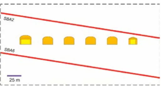
The UDEC model geometry for the SFR 3 extension includes six adjacent vaults as shown in Figure 7 and Figure 9 (2BMA, 5BLA, 4BLA, 3BLA, 2BLA, 1BRT). The 2-D profiles provided in SKB TR-14-01 were used, maintaining the minor
differences in dimensions compared to the rock vaults of SFR 1 (Figure 8). These follow the dimensions according to Layout 2.0 (as reported in SKB TR-14-01), whereas SKB TR-14-01 (p. 84) reports that the dimensions of Layout 1.5 were used in the modelling for the SR-PSU long-term safety assessment. The main difference between these, relevant to the 2-D UDEC models developed, is that 2BMA in Layout 2.0 is 0.4 m shorter and 0.6 m wider. Not provided in any of the drawings in
SKB TR-14-01, or any of the associated reports, are the planned spacings between the adjacent rock vaults in SFR 3. SKB R-14-17 (p. 58) reports that the width of the pillars separating the SFR 3 rock vaults will range from a width to height ratio of 0.75 to 1. This range was adopted for the SFR 3 spacings used in the UDEC models as represented in Figure 9. The depth of the SFR 3 extension is reported in SKB TR-14-01 (p. 83) as involving 120 m of rock cover. Based on the description of design constraints for SFR 3 (SKB R-14-17), the depth of the rock vaults was modelled so that the roof of the highest cavern in the repository is set at around -120 m.
Figure 9: (Top) Constructed vertical section through the planned SFR 3 rock vaults assuming
20 m pillar widths, and (bottom) detailed dimensions of the 2BMA, 5-2BLA and 1BRT vaults from SKB TR-14-01.
The external dimensions of the 3DEC model of SFR 1 in SKB R-13-53 is a block that is 240 m long, 140 m wide and 100 m high. For the purpose of the UDEC analyses performed here, these boundaries were viewed as being closer to the modelled rooms than would normally be recommended, and necessitated due to the more intensive computing requirements of 3DEC. For the UDEC models, we assume external boundaries that extend at least 240 m laterally and 220 m vertically from the outer walls and floors of the outer rock vaults in each sequence. For SFR 1, this results in a block that is 600 m wide and 300 m high, and for SFR 3, a block that is 680 m wide and 360 m high.
3.3.2. Geology and Deformation Zones
The geology of the SFR is described in SKB TR-14-01 as involving four domains: RFR01 to RFR04. For the most part, the SFR is situated in RFR02 (Figure 10), which is described as being heterogeneous and consisting of fine- to medium-grained metagranite-granodiorite. The domain also contains 24% pegmatite and pegamitic granite.