Mälardalen University, Västerås, 2015-05-27 School of Innovation, Design and Engineering
Thesis for the Degree of Bachelor in Computer Science
Thesis Supervisor: Mobyen Uddin Ahmed
Thesis Examiner: Mats Björkman
Students: Sverker Ekberg
Alexander Martin
seg12002@student.mdh.se amn12005@student.mdh.se
A Generic System-level Framework for
Intelligent Sensor Data Management
2
Abstract
Drug stores sell them, warehouse stores sell them, your doctor probably uses them - health sensing equipment used to monitor bodily data is on the upswing. Several brands have released their own weighing scales, blood pressure monitors, pulse bands etc., together with their own smartphone applications. However, the usage of sensor devices in a medical environment is in need of a general framework that can be a base for implementing systems capable of handling a wide range of sensor devices. A patient using a sensor, taking a measurement, uploads the data with a collector (e.g. smartphone) to a gateway (i.e. web service) where medical personnel can use the data to evaluate a person's health or raise an alarm if a person is at risk. A study on existing frameworks led to the design and implementation of a framework that handles generic sensor data transportation between (i) sensors and the collector and (ii) the collector and a gateway, using the Android platform. The work resulted in an implemented Android framework (called SFW) and a prototype using the framework; consisting of an Android user application and a RESTful web service. Functional testing was used to evaluate the framework where three different sensor devices plus one simulated configurable “sensor” were used to verify that the framework can handle different types of measurement data. The experimental evaluations show that SFW is capable in handling generic sensors' measurements but still contains possible areas of improvements such as implementation of encryption and, in the future, further evaluation.
3
Table of Contents
1. Introduction ... 6 1.1 Problem Formulation ... 7 1.2 Problem Discussion ... 7 2. Background ... 8 2.1 Internet of Things ... 82.2 Sensor Usage in a Medical-Care Environment ... 8
2.3 Frameworks ... 9
3. State of the Art... 10
3.1 Communication Protocols ... 10
3.2 Web Service Protocols ... 10
3.3 Existing Frameworks ... 11
3.3.1 Funf Open Sensing Framework ... 11
3.3.2 Open Data Kit (ODK) Sensors ... 11
3.3.3 Mobile Sensing Framework (MSF) ... 11
4. Method ... 13 4.1 Literature Study ... 13 4.2 Framework Design ... 13 4.3 Implementation ... 13 4.4 Evaluation ... 14 5. Framework Design ... 15
5.1 A Generalized Way of Packaging Data ... 15
5.2 Android Application (Collector) ... 15
5.3 Web Service (Gateway) ... 16
5.4 Requirements ... 16
5.4.1 Functional Requirements ... 16
5.4.2 Non-Functional Requirements... 16
6. Result ... 17
6.1 Framework Specification ... 17
6.1.1 Overview of the Framework ... 17
6.1.2 Representing Information ... 18
6.1.3 Interface Specifications ... 19
6.1.4 Web Service Communication ... 24
6.2 Implementation ... 25
6.2.1 Framework Composition ... 26
6.2.2 Prototype Using the Framework ... 27
7. Evaluation and Discussion ... 29
7.1 Functional Testing ... 29
7.1.1 Test Devices... 29
7.1.2 Functional Test Cases... 31
7.1.3 Testing Response Times ... 32
7.1.4 Verifying Web-Service Functionality ... 32
7.1.5 Discussion ... 33
7.2 Results Discussion... 34
7.2.1 Results Compared to Related Research ... 35
8. Conclusion ... 37
8.1 Future Work... 37
References ... 38
4
List of Figures
FIGURE 1.STATE MACHINE DIAGRAM OF THE METHOD. ... 13
FIGURE 2.ILLUSTRATION OF FRAMEWORK COMPONENTS AND COMMUNICATION. ... 15
FIGURE 3.AN OVERVIEW OF THE COLLECTOR DEVICE. ... 17
FIGURE 4.ILLUSTRATION OF A USER, REPRESENTED AS A JSON OBJECT. ... 18
FIGURE 5.INTERFACES (NON COLORED) USED FOR COMMUNICATION. ... 19
FIGURE 6.DESCRIBING THE SEQUENCE OF ACTIONS TAKEN WHEN A MEASUREMENT IS RECEIVED. ... 26
FIGURE 7.SHOWING A SELECTED USER WITH TWO SENSORS; ONE OF WHICH IS STARTED... 27
FIGURE 8.POP-UP FRAGMENT FOR ADDING A USER VIA VERIFICATION. ... 27
FIGURE 9.MEASUREMENT LOGBOOK. ... 27
FIGURE 10.THE OMRON 708-BT BLOOD PRESSURE MONITOR. ... 30
FIGURE 11.THE OMRON BF206-BT WEIGHING SCALE. ... 30
FIGURE 12.ANDROID-BASED SIMULATED HEART-RATE SENSOR. ... 30
FIGURE 13.ANDROID-BASED BAROMETRIC SENSOR. ... 30
FIGURE 14.MEASURING RESPONSE TIMES. ... 32
5
List of Tables
TABLE 1.FIVE COMMUNICATION PROTOCOLS USED BY SMARTPHONES AND SENSOR NETWORKS. ... 10
TABLE 2.A COMPARISON OF THREE FRAMEWORKS. ... 12
TABLE 3.ISENSORDRIVER -INTERFACE NECESSARY TO BE IMPLEMENTED BY ALL DRIVERS. ... 20
TABLE 4.METHODS IN THE ISENSORDRIVERLISTENER INTERFACE... 20
TABLE 5.METHODS IN THE ISENSORLISTENER INTERFACE... 21
TABLE 6.METHODS IN THE ISFWMANAGER INTERFACE. ... 22
TABLE 7.METHODS IN THE ISFWMANAGERLISTENER INTERFACE. ... 23
TABLE 8.CALLBACK INTERFACES USED WHEN CALLING ASYNCHRONOUS METHODS ON THE ISFWMANAGER. ... 23
TABLE 9.WEB SERVICE REQUIRED FUNCTIONALITY FOR INTERACTION WITH CORE FRAMEWORK IMPLEMENTATION. ... 25
TABLE 10.DESCRIPTION OF EACH FUNCTIONAL TEST AND THE EXPECTED OUTCOME. ... 31
TABLE 11.RESULT TIMES (IN MILLISECONDS). ... 32
TABLE 12.TEST CASES USING CURL TO VERIFY TRANSPORT OF DATA AND RESPONSE. ... 33
List of Tables: Appendix A
TABLE A.1.THE FIRST SET OF MEASUREMENTS. ... 40TABLE A.2.A SECOND SET OF MEASUREMENTS. ... 40
TABLE A.3.THIRD SET OF MEASUREMENTS. ... 40
TABLE A.4.FOURTH SET OF MEASUREMENT. ... 41
TABLE A.5.AVERAGE OF FOUR TRANSMISSIONS. ... 41
TABLE A.6.HIGHEST RESPONSE TIME OF FOUR TRANSMISSIONS. ... 41
6
1. Introduction
The rapid evolution of modern technologies includes smart solutions for everyday life, not just among the young, but for the elderly which are a rapidly growing part of the population. According to estimates by the United Nations [1], the number of elderly (60 years and older) will be twice as many by the year 2050 compared to 2007. This will create an increased demand for more caregivers and health personnel if the quality of health care shall be maintained at the same level as it is today. To optimize resources and at the same time let the elderly keep living at home, a significant amount of research has been done in the area of sensor networks [2]. The production and use of smartphones is increasing at a rapid rate as well; almost half a billion smartphone devices were activated in 2014, according to statistics published by Cisco in February 2015 [3].
The increasing availability of advanced mobile devices increases the feasibility of a whole new range of life-improvement opportunities. Use of modern technology could enable medical personnel to know whether a patient has taken his/her medications or not; provided that the medicine is stored or handled by a sensor connected to the system. It could also detect if a person has experienced a falling accident, which is a common source of injuries/suffering for senior citizens [4]. Additionally, continuous monitoring of individuals’ vital signs in their different environments enables early-warning functionality, e.g. letting an individual and/or their caregiver know if measured blood pressure has been unusually high for a period of time, or warning medical services that an individual is experiencing a heart attack. It is easy to realize that by making use of automatic monitoring, most areas within health care could be further improved, while at the same time reducing financial costs by reducing the demand of additional required medical personnel as a result of the increasing elderly population.
Several consumer-targeted physiological sensor measurement products have become available during the last few years (e.g. Andersson Lifesense [5], Beurer [6] and iHealth [7]) however; most of these products function as closed platforms, preventing the devices from interacting with third-party systems, despite being very similar in functionality. An exception to this is Angel [8], a sensor wristband crowdfunded in 2013 with the highlight being its open-source functionality; the creators make available a software development kit (SDK). However; developers still need to learn and implement an API specific for the device. By basing the software of sensor products on a generic framework, users would be able to mix and match hardware and software according to individual requirements and conditions.
Open-source framework solutions with the common goal to unify the diversity of sensors have been defined and developed during the past few years, but many of these frameworks have primarily been focused toward ease-of-use of the already built-in sensors in a device. The analysis primarily concentrates on three open-source sensor management frameworks; Open Data Kit (ODK) Sensors [9], Funf [10], and Mobile Sensing Framework (MSF) [11]. ODK Sensors is currently in its development phase. Its primary purpose is to enable developers in third-world countries to create applications containing necessary functionality despite eventual lack of extensive knowledge of development techniques and methods [12]. Funf was first released in late 2011 but has undergone several updates since. It is primarily aimed towards the capture of built-in sensor device data or manual input information, but also offers the ability to create own components, so-called probes, to support additional functionality. MSF is a relatively recent contribution, described in a paper published in 2013; the creators present MSF as a proposal for a fourth generation type of generic framework, with primary focus being on performance effectiveness.
The purpose of this report is to describe the process of defining a framework that generalizes management of physiological sensor data from capture to storage. Current state of the art (i.e. existing solutions and techniques related to the problems) is presented and analyzed in order to provide the background of which a general solution is based. After the introduction in the first
7
section, the problem formulation is presented. Section 2 covers the background of the work followed by Section 3, where current state of the art is formulated and discussed. Section 4 describes the methodology used to design, implement and evaluate the framework. Initial design aspects are briefly presented in Section 5, followed by Section 6 which presents the result of the work. The results are evaluated and discussed in Section 7. The conclusions of the work, including ideas for future work, sums up the report in Section 8.
1.1 Problem Formulation
The goal of the thesis was to, based on a literature study, define and implement a generic framework for collection of physiological data from smart sensors. The data transported between the sensors and storage server is to be handled in a reliant manner, using closed-loop feedback and control in each step of the framework. This raises several questions on how to best manage sensor data; how to package it, which network that should be chosen (based on critical level of data) to send and receive data, how to represent close-by sensors and connect them to the framework in a plug-and-play fashion. In regards to this, questions are formulated as follows:
1. Given current research and prototypes of sensor systems, how can the similarities and differences be abstracted into a common generic framework?
a. What information is required to sufficiently support different kinds of physiological sensor data?
2.
Is it possible to get a reliant system, i.e. a system that is able to send and receive information from first to last node with closed loop feedback in every step, and still guarantee that the information is received at the end station?a. How can deviations from desired outcome be handled if a system fails?
1.2 Problem Discussion
Currently, there are multiple frameworks that attempt to generalize the handling of arbitrary sensor data. Many of these solutions often aim to cover an immensely broad usage domain, which could be a cause of unnecessary complex functionality. At the same time, they offer different end nodes for the data to be sent to, e.g. some frameworks are limited to local data storage and do not include functionality for data communication to a remote storage. By addressing these and trying to define a generic framework aimed at physiological sensors, it should be possible to get a more lightweight framework that supports the requirements for medical use where safe delivery of information is important and still supports the variety of sensors available for the existing frameworks. This problem formulation might contribute with some new questions though, e.g. what is considered a “reliant system”; is it a system that never needs a restart, a system that is secure against malicious attacks or double checks that information has reached the goal? Since there is a need to limit the scope of the problem, it has been decided that the system is supposed to be able to be reliant in the way that the information reaches the target platform.
8
2. Background
A generic framework for physiological sensors has a chain of underlying models and theories that needs to be addressed to give the best possible foundation to design upon. In this section, an overview of these fundamental parts will be provided, leading up to frameworks.
2.1 Internet of Things
The noun “Things” in the Internet of Things (IoT) refers to the information that is collected by a device, and not the device itself. Huang and Li [13] describes the term as the information of a thing that is shared to the world by an Internet application. Compared to the input into a webpage form, IoT is to be seen as information read by a machine and not as information manually created and inputted by the user. IoT can be seen as a process where the thing’s information is somehow read (e.g. by a Radio-frequency identification (RFID) reader), it is stored and distributed over the Internet and finally the information is downloaded and used by clients. The clients however, do not need to be human. The communications will be between human-human, human-thing and thing-thing [14], which could be seen a great extension from how Internet has been used over the last four decades. The communication protocols that already can be used in IoT are many, e.g. RFID, digital subscriber line (DSL), general packet radio service (GPRS), wireless local area network (WiFi), local area network (LAN), third generation of mobile telecommunications technology (3G) [14] and Bluetooth. The infrastructure is already in place and allows for different devices to be connected, both to the Internet but also directly between devices.
IoT has a broad area of applications, many related to the health-care sector. One of these areas could be improved identification of medical equipment and medication to avoid counterfeit products; if each produced item can be uniquely identified (e.g. by attachment of an RFID device), and information associated with these identifiers is available (e.g. through a public database), then the ability for both patients and medical personnel to verify the origin and validity of such items would be greatly increased. Being able to access information associated with unique items would also enable easier handling and recollection of usage instructions (e.g. dosage strength and intervals), allergy information etc., which could otherwise be tedious or otherwise cumbersome to make available. [15]
2.2 Sensor Usage in a Medical-Care Environment
The idea of the IoT entails the possibility for new solutions in health care, such as sensor networks using wireless ZigBee networks to detect if an elderly person falls. Chen [16] presents such a solution where ZigBee beacons are placed in a room to detect a waist-mounted sensor’s location measured in all directions. In this solution a person falling can be detected as well as their position in the room. Another medical solution uses Near Field Communication (NFC), often used in smartphones for payment or file transfer between devices, to let patients read data from a body-mounted sensor to the smartphone for later transferal to a caregiver [17].
The field of health care-related sensor technology research is large and this also shows on the consumer market. Several health and fitness related applications have been released, where this kind of medical equipment can be connected to smartphones with applications that gather data (and in some cases also allow users to publish data at social media). One such device is the Andersson Lifesense [5] that supports several sensor devices to measure physiological information and collect it on the user’s smartphone via Bluetooth. The application that is provided can archive data as well as compile and present it as graphs on screen.
9
2.3 Frameworks
A framework is an abstract design and implementation for a specific purpose of software [18]. In the same way as object-oriented programming is used for reuse of code, frameworks provide generic functionality which developers can modify and extend to adapt it to specific applications. Generic frameworks facilitate rapid development, by allowing developers to reuse or extend specific components, and can permit users to handle components the same way, e.g. letting sensor devices created by different companies be connected to the same smartphone application. State of the art focuses on three such sensor-management frameworks, along with techniques related to the area.
10
3. State of the Art
There are several existing technologies that relate to the problem area. By compiling key elements from important fields, the aim is to give the reader an overview over the current state of the art. This section focuses on; communication protocols (WiFi, Bluetooth, ZigBee, Universal Serial Bus (USB), and RFID), web-service protocols (SOAP and REST), and sensor-management frameworks (Funf, ODK Sensors, and MSF).
3.1 Communication Protocols
There are several dominant wireless communication protocols that are commonly used to manage interaction with a wide range of sensor devices, the most prominent protocols being Bluetooth, ZigBee, RFID and USB, listed compared in Table 1.
Technology WiFi Bluetooth ZigBee RFID USB
Supports Sending Data
Yes Yes Yes Yes Yes
Supports Receiving Data
Yes Yes Yes Requires active RFID
chips.
Yes
Wireless Yes Yes Yes Yes No
Data Rate 600 Mbps (based
on [19]) 24 Mbps 20-250 kbps Up to 640 kbps 400+ Mbps Maximum Distance Up to 100m Up to 100m Up to 100m Up to 200m 3m1)
Table 1. Five communication protocols used by smartphones and sensor networks.
3.2 Web Service Protocols
There exist several different web service protocols that are used for interaction with web services. Two protocols were chosen to look further into; SOAP and Representational State Transfer (REST), since the use of Extensible Markup Language (XML) (used in SOAP) is wide on the Internet as well as in non-Internet-related software. REST is an interesting alternative to SOAP, because of its light weight.
SOAP [21] is a protocol that specifies how data is to be represented as a package to and from a web service. The package is structured using XML to define an envelope containing; the information that it is a SOAP message and a body containing call and response information, but also permits the usage of a header containing header information and a “fault”-part with information about processing errors.
REST was developed to be a simpler alternative to SOAP. It consists of guidelines and best practices for communication between client and server (web service in most cases). REST do not specify how data is to be represented (i.e. structured), it is up to the specific implementations how it should be done [22]. Examples of standards of data representation include JavaScript Object Notation (JSON) [23] and XML.
1)
11
3.3 Existing Frameworks
As presented in Introduction, the use of physiological sensors connected to smart devices is becoming increasingly common, both in research, but also in the market accessible to the general public. However, the current solutions are following different standards, i.e. different connection protocols and different ways of handling the data, which means that it becomes a reinvention every time a company presents a new solution. This could be handled by an efficient framework that could make implementation easier. Some of the current contributions within this field are Funf, ODK Sensors, and MSF presented in coming subsections.
Besides current frameworks, research is actively done and tested [24] in the area to provide a health-care solution that can be used in the future of health health-care, as well as its usefulness [25]. Ahmed et. al. [26] propose a generic system-level framework for health monitoring, quite relevant for this thesis, but the work is not published until this summer (2015).
3.3.1 Funf Open Sensing Framework
Funf Open Sensing Framework [10], first released in late 2011, is a popular framework for Android applications which primarily focuses on making it easier for users to handle built-in sensors. Key features include support for automatic collection, both active and background based, and uploading of sensor data. Funf is delay tolerant, i.e. it can handle intermediate storage while a connection is missing and resume data upload when connection is reestablished. The framework primarily permits interaction with built in sensors such as gyroscope and GPS, however; Funf is an open source framework [27], permitting 3rd party developers to create and modify probes. Collected data is handled with consideration to user privacy by storing all sensitive user data (such as SMS, phonebook contacts, history etc., depending on probe type) as hash values instead of clear text in the database. Users are uniquely identified based on phone ID instead of e.g. social security number.
3.3.2 Open Data Kit (ODK) Sensors
ODK Sensors [9] is an open source framework in the development phase for Android devices [12]. The primary purpose of the ODK Sensors framework is to facilitate easier development of applications that collect sensor information, reducing demand for experienced developers; deployment being aimed at third-world countries where such experience may be in short supply. The ODK Sensors framework handles communication with built in sensors (e.g. GPS and accelerometer) and external sensors (i.e. connected through Bluetooth, ZigBee etc.) the same way; through a single unified driver interface. Sensor device drivers are implemented as user-level applications using Android APIs, each driver being run as a separate application, thus allowing the framework to function in its entirety on a standard Android device, i.e. there are no demands that the operating system is to be modified or unlocked in some way. Drivers can be reused throughout multiple user applications.
3.3.3 Mobile Sensing Framework (MSF)
MSF is a framework published in 2013 [11] with the goal to mask low-level technical details related to the handling of sensor data while at the same time allowing developers to use both raw sensor data as well as sensor data that have been analyzed and processed into high-level conclusions, e.g. detection of a fall. Other targeted areas of improvements are more effective of resource reuse and customizable duty schemes to improve raw performance. The Mobile Sensing Framework allows for continuous sensing by pausing the active sensors when external events occur to reduce impact on the user experience, and can later resume data collection when suitable. All interactions between framework components are done through different layers in order to improve reusability and avoid issues in cases where objects would be changed from a number of different modules.
12
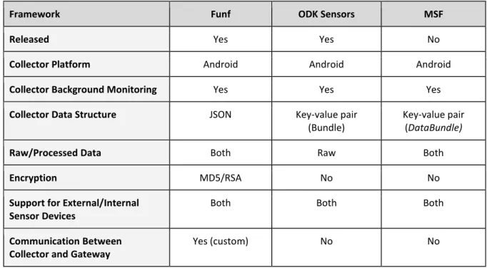
Framework Funf ODK Sensors MSF
Released Yes Yes No
Collector Platform Android Android Android
Collector Background Monitoring Yes Yes Yes
Collector Data Structure JSON Key-value pair
(Bundle)
Key-value pair (DataBundle)
Raw/Processed Data Both Raw Both
Encryption MD5/RSA No No
Support for External/Internal Sensor Devices
Both Both Both
Communication Between Collector and Gateway
Yes (custom) No No
Table 2. A comparison of three frameworks.
As can be seen in Table 2, the compared frameworks are developed specifically for Android; a reason for this being that iOS normally restrict applications from running in the background, which complicates the ability for continuous measuring [11][28]. Each framework uses key-value-pair objects; ODK Sensors and MSF uses it to represent the data itself while Funf structures data in JSON format, although still storing the text-string itself inside a key-value-pair container. Only Funf and MSF support processed data, i.e. filtered or otherwise transformed measurements based on one or more sources of raw data. It appears that encryption has not been prioritized during development of these frameworks, the exception being Funf. Although Funf primarily focuses on built-in sensors, it still, along with ODK Sensors and MSF, supports both internal and external sensors. A final note is that the frameworks (the exception being Funf, which include rudimentary support) omit communication between collector and gateway, leaving this in the hands of the user application developer.
13
4. Method
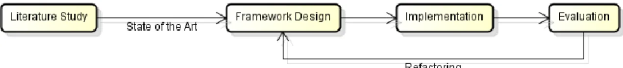
This section describes the method used to reach the described goal of the thesis. The work is divided into four phases; literature study, framework design, implementation, and evaluation. Initial research is based on a literature study, examining existing products, frameworks and other techniques. A possibility would be to perform other forms of studies, e.g. user surveys, to capture more detailed requirements. However, these were not performed due to the nature of the work and the time limitations imposed by the thesis process. Framework design is built on the result from the initial research phase, after which implementation is provided. The latter also involves evaluation of the work, described in this section. The processes described are depicted in Figure 1.
Figure 1. State machine diagram of the method.
4.1 Literature Study
The initial phase of the project involved a literature study; a comparative study of existing products and system solutions with related techniques. The selection of information sources have primarily been based on their relation to the handling and mediation of sensor data and actuality of the work. The study emphasizes the examination of similarities and differences related to functionality such as; communication between sensor and collector as well as between collector and gateway, and how sensor data is represented in the different parts of the system, but also other relevant techniques. Relevant key concepts of the related work are summarized using a concept-centric table, as suggested by Webster and Watson [29]. Current state of the art is described based on the literature study as well as today's industrial standard.
4.2 Framework Design
Initial design resulted in the definition of framework requirements, i.e. demands and limitations, which are derived from the given problem description and current state of the art. Requirements further strengthen the foundation which is the basis for the framework specification task.
4.3 Implementation
Based on previously mentioned study and design, a prototype implementation of the developed framework is tested and validated against the specified requirements and expected outcome. The framework consists of a collector, which is implemented in the form of an Android application, communicating with a gateway, i.e. web service, and sensor devices. Primary software development methodology used during implementation of the framework was iterative and incremental based.
14
4.4 Evaluation
During the implementation, testing was performed on a regular basis when new components were developed and integrated, using both software-simulated stub sensor data, i.e. made up data, an Omron BF206-BT weighing scale and an Omron 708-BT blood pressure monitor. This was possible for both the Android device and the web service. The latter was tested with fake data packages during the early implementation due to the unfinished framework.
The resulting implementation is intended as a relatively basic and simple example user application, which makes use of a prototype of the defined framework. Emphasis is not directed toward features related to user interaction, making evaluation of usability through user tests involving potential target audiences (e.g. elderly people and medical personnel) redundant and was therefore not performed. However, the framework was tested and evaluated through the use of the implemented application together with two Android based devices (barometric sensor and simulated heart rate) and two medical devices; the Omron 708-BT blood pressure monitor and BF206-BT weighing scale. The results are compared to the framework requirements definition and thesis problem formulation for validation.
15
5. Framework Design
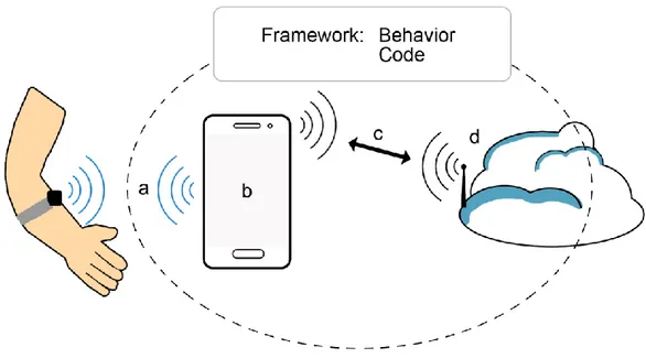
The framework covers communication between sensor device and collector, and between collector and gateway; which means that the modification of the software of sensor devices is not included within the scope (i.e. programming of sensor hardware), and neither how storage is handled by the gateway (e.g. communication with, and choice of, database), although the latter is part of the implementation. The design of the framework derives from an overview of the framework’s area of use and the natural components with which it will be used. The framework design is based on a set of rules and restrictions on; how a connection protocol in between physiological sensor(s) and Android application (collector) is to be implemented, and how data is to be sent or retrieved to/from a web service (gateway). Figure 2 illustrates the components of the framework and how they relate to each other. The framework handles the communication between collector (b) and gateway (d), which can be used by user applications that follows the specified rules and restrictions. The designed framework handles measurement data retrieved from sensors (a) by a collector. The collector packages the measurement data and sends the package to the web service (d) via a wireless network (c).
Figure 2. Illustration of framework components and communication.
5.1 A Generalized Way of Packaging Data
The data is managed in a way, such that sensor data type is of no concern for the framework. The packaging of data is able to hold all necessary information from a sensor. The packaging raises the question of encryption and checksums to protect the data and provide confirmation that the package has reached its destination.
5.2 Android Application (Collector)
An application that physiological sensors can easily connect and send their data to via Bluetooth, Wi-Fi, NFC or other data connection depending on the collector and sensor devices’ capabilities and preferences. The application is following the generalized framework design and also include a convenient graphical user interface, that is used to manage sensors (i.e. manage connection to one or more sensors), users, and show a history of measurements.
16
5.3 Web Service (Gateway)
A web service that the Android device finds a suitable way to connect and send the packages to, for further data management (storage in database). The web service follows the specified framework design and its restrictions. The gateway stores the data in a convenient way (MySQL database) for further usage by a client e.g. medical staff.
5.4 Requirements
It is important that the different sensors (and their respective collectors) can be added and removed in a plug-and-play fashion in order to facilitate ease of use. From the framework design, this should be easily managed if rules and restrictions are followed, as designed in the framework.
The design of the framework is abstracted from this description into a set of functional and non-functional requirements that were used as guidelines while designing and implementing the framework.
5.4.1 Functional Requirements
1. All connected sensors are to be handled through the same interface. 2. A sensor should only need one driver to be functioning with the system.
3. Several sensors of the same model should be able to function with one and only driver. 4. The framework should be able to automatically send captured data to the web service. 5. There should be a unique identifier for each user, and a unique identifier for each device. 6. Framework should use a data type suitable for the task.
5.4.2 Non-Functional Requirements
1. System is to be reliant, using closed-loop feedback to send and retrieve data.
2. The framework should choose the most optimal method of communication with the web service.
3. Data that is lost in transmission should be sent again.
4. Framework should be able to handle arbitrary data from sensors.
5. System data packages should not be editable between collector and gateway without end node (gateway) knowing about it. I.e. a tempered package should not be accepted by the gateway.
6. Framework should be intended for (but not necessarily limited to) usage in medical health, e.g. not be general to handle extra functionality that is not a part of sensor data readings and sending the information.
17
6. Result
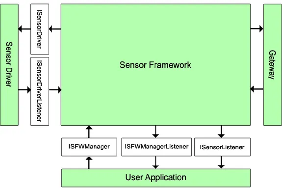
The results can be separated into two primary categories; the specification of the framework and its communication with internal (e.g. drivers) and external (e.g. web service) components, and the implementation of the framework (according to specification). Figure 3 provides an overview of the collector (consisting of the sensor framework, user application and sensor drivers), communicating with a sensor device and a gateway. Arrows mark the direction of communication.
Figure 3. An overview of the collector device.
6.1 Framework Specification
The developed framework consists of internal communication that handles messages from the sensor driver to the collector and sending/retrieval of information over the network. To access this communication a set of interfaces has been defined to be used by a developer implementing a sensor driver and a user application to use the ISFWManager implementation for sensor and web service communication. This section gives an overview of how common information is represented (measurements, users, and sensors), the interfaces that are used between components (including the external web-service interface) as well as more detailed description of the methods accessible through these different interfaces.
6.1.1 Overview of the Framework
The framework is an Android-implemented framework with a set of rules that defines how an interaction with sensor devices is handled to let the framework transport data from the sensor to a web service. Information (measurements, users, sensors) require a structured way to be represented, as they are commonly used throughout the framework and in communication with outside components. The rules given in communication between a sensor and the collector running Android is that the sensor driver must implement the ISensorDriver interface to be able to communicate through the framework. However, the drivers and user applications are never directly connected, instead, they communicate through the ISFWManager interface (or via callback objects passed into the ISFWManager’s methods), which acts more or less like the primary hub in the framework, also handling communication between the sensor drivers and gateway (i.e. web service).
18
The framework automatically attempts to upload measurements when received from sensors (through the respective sensor’s driver, which implements the ISensorDriver interface). Any listeners (usually just one or a few of the user application’s activities) registered to receive general framework events are notified when a measurement have either succeeded or failed to be uploaded to the gateway.
When the framework is communicating with the web service over Internet, it uses HTTP status codes in headers and data packages to do transfer in between the collector and web service. In return, the web service responds with HTTP headers to tell if the request or transfer went well or not. These HTTP status codes and what comes with them (in the form of data packages) is the given rules for communicating with the framework from a web service.
6.1.2 Representing Information
There are three structures which are commonly used by, and passed around the framework, each representing one of three basic components; sensor measurements, user information, and sensor information.
Sensor measurements are internally represented as byte arrays, which enable the application
developer to use any kind of data representation object while at the same time reducing the need for the developer to make changes to the internal workings of the framework.
User information is represented as JSON objects; each object representing a single user. Each JSON
object that represents a user is required to have three keys with respective values; “userid”, “privatekey”, and “sensors”. “userid” points to a string value that uniquely identifies a specific user while the value represented by “privatekey” is the user’s private key, i.e. password, also a string value, which is used, in combination with other information, to authenticate the user, e.g. for communication with the web service (gateway). The third required value, represented by the “sensors” key, is a JSON array; containing zero or more JSON objects, each one representing information about a sensor. Figure 4 illustrates how a JSON object representing a user containing required fields and one sensor may look like.
{ “userid” : ”883510155”, “privatekey” : ”YyD+puY23svvGrWNRNUtf4MH7bkdoy8zIun5bOWX/L+VOgDl/KXM”, “sensors” : [ { “userid” : “883510155”, “id” : “AGENT-007”, “class” : “mdh.sfw.BarometerSensorDriver” } ] }
Figure 4. Illustration of a user, represented as a JSON object.
Sensor information is, like user information, represented as JSON objects. These objects are normally
contained inside user information objects (represented by the “sensors” key, described above), but can also be contained on their own, then usually as part of a JSON array. Each sensor information object is required to contain the following keys, each one representing a string value: “userid” uniquely represents the user associated with this sensor; “id” represents the unique identifier of this sensor; “class” contains the name of the class that is a driver compatible with the sensor. Additionally, an optional key called “host” can be used to specify a host, as a string value, that is specifically used by this sensor when uploading and downloading sensor measurements through the gateway layer.
Developers using these structures, or more specifically the JSON objects representing the user and sensor information, are required to provide the above key-value pairs. However; additional implementation-specific values can also be included, e.g. fields for user weight and height.
19
6.1.3 Interface Specifications
Several interfaces (depicted in Figure. 5, arrows shows communication direction) have been specified to allow for developers to implement or extend components that interact with the framework. By implementing the ISensorDriver, the developer can set up new sensor devices, physical or otherwise, that are capable of communicating with the framework. The ISFWManager interface can be considered as the main hub; it channels all communication between the framework and any user application(s), where e.g. measurements can be displayed or sensors connected/disconnected, allowing for the developer to implement user applications where both data and sensor activity can be handled all through the same interface. Additionally, there are several other interfaces used to enable message passing inside and outside the framework; ISensorDriverListener, ISensorListener, ISFWManagerListener. Finally, there are four smaller callback listener interfaces, which are used to receive information about results of methods (called on the ISFWManager implementation) that perform asynchronous operations such as network communication.
20
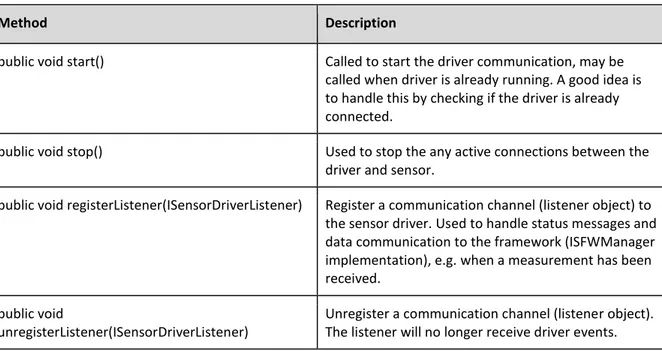
ISensorDriver is an interface (presented in Table 3) used to implement drivers that are able to communicate through the framework. Using a class that implements this interface, the developer gets access to four methods that handle the communication to and from the framework. It also gives the possibility to get hold of the messages from other parts of the framework, e.g. to communicate with the user application. Note that it is only the ISFWManager implementation that normally has direct access to ISensorDriver implementations; user applications should channel any sensor communication via the ISFWManager interface.
Method Description
public void start() Called to start the driver communication, may be called when driver is already running. A good idea is to handle this by checking if the driver is already connected.
public void stop() Used to stop the any active connections between the driver and sensor.
public void registerListener(ISensorDriverListener) Register a communication channel (listener object) to the sensor driver. Used to handle status messages and data communication to the framework (ISFWManager implementation), e.g. when a measurement has been received.
public void
unregisterListener(ISensorDriverListener)
Unregister a communication channel (listener object). The listener will no longer receive driver events. Table 3. ISensorDriver - Interface necessary to be implemented by all drivers.
Implementations of the ISensorDriverListener interface are created by the framework (more specifically the ISFWManager implementation) and are used as callback (or listener) objects, which are registered on one or more drivers. The driver implementations use these callback objects to communicate with the framework. The interface methods (see Table 4) are called by the driver implementation (to which the specific object(s) have been registered) to notify the framework of several events, e.g. when a sensor has been started or stopped. Note that user application is not intended to utilize this interface, they should instead make use of the ISensorListener interface (described below) which provide similar functionality.
Method Description
public void onSensorStarted() Called by the sensor driver when the sensor has been started. public void onSensorStopped() Called by the sensor driver when the sensor has been stopped. public void onSensorDisconnected() Called by the sensor driver when the sensor has been
disconnected from a sensor device.
public void onSensorConnected() Called by the sensor driver when the sensor has been connected to a sensor device.
public void onDataReceived(byte[]) Called by the sensor driver when it has received data from the sensor device and is able to send the data to the framework. Table 4. Methods in the ISensorDriverListener interface.
21
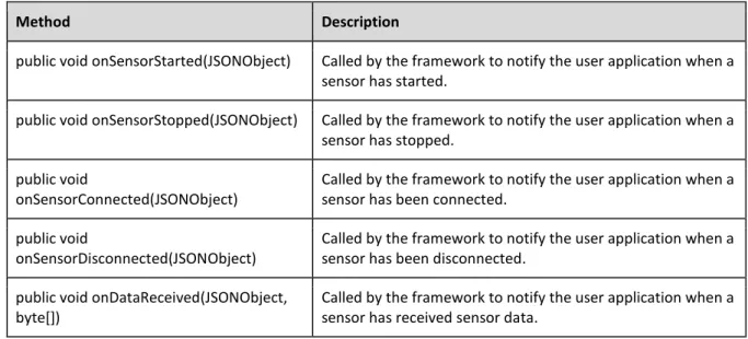
ISensorListener acts as a filter or abstraction, the ISensorListener is used in the framework as a communication channel in between the user applications (if and when desired) and the framework hub, i.e. the ISFWManager implementation. By implementing this type of listener, whose methods are described in Table 5 (used to communicate in between user application and the framework), the user applications can listen to sensor activity and receive transmitted data (i.e. measurements) originating from sensor drivers. As of now, the usage of these listeners allows for future extensions of how the framework handles the data before the user application gets access to it.
Method Description
public void onSensorStarted(JSONObject) Called by the framework to notify the user application when a sensor has started.
public void onSensorStopped(JSONObject) Called by the framework to notify the user application when a sensor has stopped.
public void
onSensorConnected(JSONObject)
Called by the framework to notify the user application when a sensor has been connected.
public void
onSensorDisconnected(JSONObject)
Called by the framework to notify the user application when a sensor has been disconnected.
public void onDataReceived(JSONObject, byte[])
Called by the framework to notify the user application when a sensor has received sensor data.
Table 5. Methods in the ISensorListener interface.
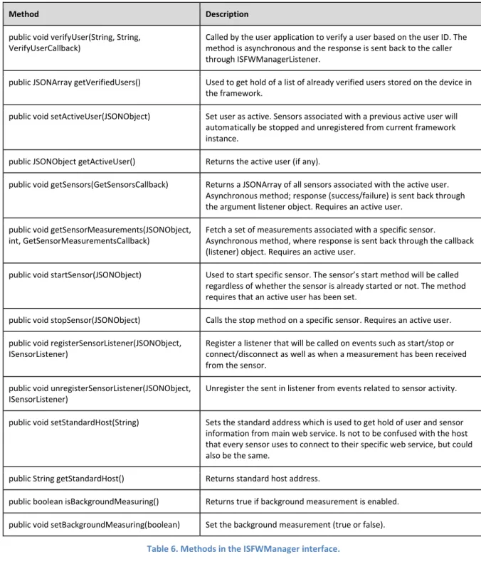
ISFWManager acts as the main hub inside the framework, channeling communication between both internal and external components; i.e. drivers, web service, and user applications. The methods are normally used by the user applications to register for sensor events, set the standard host address, enable background monitoring etc. Many methods require that an active user has been set. Only one user can be active at a time. If the active user is changed, any currently established communication with sensor devices is aborted, i.e. sensors associated with the previous active user are disconnected from the framework. The ISFWManager’s methods are specified in Table 6. Several methods are asynchronous, making use of callback objects (see Table 8) to alert the caller (usually a user application) of result or failure. Clients are notified of general events, such as when a measurement has been uploaded to a web service, by first registering a listener of type ISFWManagerListener (see Table 7) using the ISFWManager interface methods.
22
Method Description
public void verifyUser(String, String, VerifyUserCallback)
Called by the user application to verify a user based on the user ID. The method is asynchronous and the response is sent back to the caller through ISFWManagerListener.
public JSONArray getVerifiedUsers() Used to get hold of a list of already verified users stored on the device in the framework.
public void setActiveUser(JSONObject) Set user as active. Sensors associated with a previous active user will automatically be stopped and unregistered from current framework instance.
public JSONObject getActiveUser() Returns the active user (if any).
public void getSensors(GetSensorsCallback) Returns a JSONArray of all sensors associated with the active user. Asynchronous method; response (success/failure) is sent back through the argument listener object. Requires an active user.
public void getSensorMeasurements(JSONObject, int, GetSensorMeasurementsCallback)
Fetch a set of measurements associated with a specific sensor.
Asynchronous method, where response is sent back through the callback (listener) object. Requires an active user.
public void startSensor(JSONObject) Used to start specific sensor. The sensor’s start method will be called regardless of whether the sensor is already started or not. The method requires that an active user has been set.
public void stopSensor(JSONObject) Calls the stop method on a specific sensor. Requires an active user. public void registerSensorListener(JSONObject,
ISensorListener)
Register a listener that will be called on events such as start/stop or connect/disconnect as well as when a measurement has been received from the sensor.
public void unregisterSensorListener(JSONObject, ISensorListener)
Unregister the sent in listener from events related to sensor activity.
public void setStandardHost(String) Sets the standard address which is used to get hold of user and sensor information from main web service. Is not to be confused with the host that every sensor uses to connect to their specific web service, but could also be the same.
public String getStandardHost() Returns standard host address.
public boolean isBackgroundMeasuring() Returns true if background measurement is enabled. public void setBackgroundMeasuring(boolean) Set the background measurement (true or false).
23
Implementations of the ISFWManagerListener are normally created and owned by user applications and registered with the ISFWManager implementation. The interface methods are called by the framework in order to communicate general events such as when measurements have been successfully uploaded to the remote gateway.
Method Description
public void onMeasurementUploadSuccess( JSONObject, byte[], byte[])
Called when a sensor measurement has been successfully uploaded to the web service
public void onMeasurementUploadFailure(JSONObject, byte[], int)
Called when attempted upload of measurement failed.
Table 7. Methods in the ISFWManagerListener interface.
To be able to get the result of asynchronous method called on the ISFWManager, e.g. for functionality involving network communication, four smaller callback interfaces are utilized to act as callback objects. VerifyUserCallback, GetUserCallback, GetSensorCallback, and the GetSensorMeasurementsCallback interface (see Table 8) provide methods that are called when the asynchronous message associated with it has resulted in success or failure.
ISFWManagerListener.VerifyUserCallback Method Description
public void onUserVerifySuccess(JSONObject) Used when verifying that a user exists in the gateway. Asynchronous methods that calls the methods on the callback objects on success or failure.
public void onUserVerifyFailure(String, int)
ISFWManagerListener.GetUserCallback Method Description
public void onGetUserSuccess(JSONObject) Used to download user information from gateway. Asynchronous methods that calls the methods on the callback objects on success or failure.
public void onGetUserFailure(String, int)
ISFWManagerListener.GetSensorsCallback Method Description
public void onGetSensorsSuccess(JSONArray) Used when fetching sensor information from gateway Asynchronous methods that calls the methods on the callback objects on success or failure.
public void onGetSensorsFailure(int)
ISFWManagerListener.GetSensorMeasurementsCallback Method Description
public void
onGetMeasurementsSuccess(JSONObject, byte[])
Used when fetching sensor measurements from gateway. Asynchronous methods that calls the methods on the callback objects on success or failure.
public void
onGetMeasurementsFailure(JSONObject, int)
24
6.1.4 Web Service Communication
Web services that are to interact with the framework are required to fulfill a specific RESTful architecture [22] [30]. The current core framework requires the web service to be capable of handling five specific methods, described in further detail in Table 9. Parameters passed inside the URL (as part of the HTTP method) to the web service shall be URL-encoded [31]. Transferals of byte arrays, i.e. sensor measurements, between the collector (more specifically; the GatewayLayer service component) and the gateway (i.e. web service) is done by encoding the byte information as strings using Base64.
Web Service Communication Specification
Description Get information about a specific user. HTTP Method GET {host}/users/{userid}
Request Auth. Header
SFW-AUTH time=”{time}”, hash=”{time}{userid}{privatekey}”
Request Content
-
Response 200 (OK) : JSON object representing the specific user (see 6.1.2). 401 (FAIL): Invalid authorization hash.
Description Get list of sensors associated with specific user. HTTP Method GET {host}/users/{userid}/sensors
Request Auth. Header
SFW-AUTH time=”{time}”, hash=”{time}{userid}{privatekey}”
Request Content
-
Response 200 (OK): JSON array consisting of zero or more sensors, each one represented as a JSON object (see 6.1.2).
401 (FAIL): Invalid authorization hash.
Description Get information about a specific sensor. HTTP Method GET {host}/users/{userid}/sensors/{sensorid} Request Auth.
Header
SFW-AUTH time=”{time}”, hash=”{time}{userid}{sensorid}{privatekey}”
Request Content
-
Response 200 (OK): JSON object representing the specific sensor (see 6.1.2). 401 (FAIL): Invalid authorization hash.
25
Description Get list of measurements for specific sensor. Count is an optional parameter that limits the number of returned results.
HTTP Method GET {host}/users/{userid}/sensors/{sensorid}/measurements?Count=X Request Auth.
Header
SFW-AUTH time=”{time}”, hash=”{time}{userid}{sensorid}{privatekey}”
Request Content
-
Response 200 (OK): JSON array containing zero or more measurements, each one represented as a JSON object (see 6.1.2).
401 (FAIL): Invalid authorization hash.
Description Upload a measurement associated with specific user and sensor. HTTP Method POST {host}/users/{userid}/sensors/{sensorid}/measurements Request Auth.
Header
SFW-AUTH time=”{time}”, hash=”{time}{userid}{sensorid}{requestcontent}{privatekey}”
Request Content
Base64-encoded UTF-8 character-encoded text representing the measurement.
Response 201 (Created): Base64-encoded UTF-8 character-encoded text representing stored measurement. (identical to request body, used by framework to verify data integrity) 401 (FAIL): Invalid authorization hash.
Table 9. Web service required functionality for interaction with core framework implementation.
6.1.4.1 Request Authentication
Each request contains an authentication header, consisting of information required to authenticate the user. The header consists of the authentication scheme and two key value pairs, defined according to the HTTP specification [32]. The authentication scheme for the core framework is “SFW-AUTH”. The two key-value pairs are “time” and “hash”, where the time is the same as the one used to generate the hash value. The time used in the authentication header, and to generate hash, is in the format "yyyy-MM-dd HH:mm:ss", e.g. “2015-05-11 13:37:00”, and is to be used by the web service to prevent requests from being maliciously repeated after the original request. The algorithm used to generate hash values is SHA512 [33] [34], which is commonly used both with Android and PHP. The data combined and hashed into the authentication-value differs for the different web functions (see Table 9), but is always built on the minimum values; time, user identifier, and user private key.
6.2 Implementation
The implementation can be divided into two separate categories; the implementation of the framework itself, according to the specification given in the previous section, and the prototype using the framework, which consists of the Android user application, a web service, and four sensor drivers that interact with the framework. By implementing a user application that can receive sensor information from the sensor and forward the data to a web server, refactoring the code layout and lift out parts that are not application specific, the process of developing a framework has been a process of implementation and refactoring. The resulting framework and the implementation of a
26
user application with drivers to allow communication with a couple of sensors are described in this section.
6.2.1 Framework Composition
A user application is needed to start the services in the framework. There are two services; the SFWManager and GatewayLayer. The first mentioned is working more or less like the hub in the framework, handling communication between the sensor driver and the communication to Internet, via GatewayLayer. SFWManager is also the part of the framework that is handling communication with an Android user application via the ISFWManager interface.
Figure 6. Describing the sequence of actions taken when a measurement is received.
The ISFWManager interface is implemented by a concrete class called SFWManager. This class is the main object of which communication between the user application and the framework occurs. SFWManager is a regular class, i.e. not a service or an activity, and is meant to be capable of being instantiated several times from different components simultaneously, abstracting more advanced concepts from the user application. The SFWManager class utilizes an internal service, called SFWManagerService, in order to achieve this feature and enable the framework to work and register measurements while the user application is closed or inactive. Most method calls performed on the SFWManager instance is routed through to corresponding methods on the internal service. Additonally, the SFWManagerService makes use of GatewayLayer, which is the service that performs network operations, i.e. communication with the gateway. The SFWManagerService also handles communication to and from the different sensor device drivers, i.e. classes implementing the ISensorDriver interface.
Figure 6 is a sequence diagram describing the message process during a sensor activity where a measurement is taken. The sensor communicates with the driver, which forward the measurement data into the framework via an onDataReceived message. The SFWManagerService sends an asynchronous message to the GatewayLayer as well as forwarding the message to the SFWManager to communicate it further to the user application. The GatewayLayer sends the appropriate request to the web service which will return a response with the original package. When the GatewayLayer receives a message response it will tell the SFWManagerService to message the user application. User and sensor information is handled by the SFWManagerService using an instance of the class UserInformationManager, which handles local storage of information. The information is stored as a set of strings –where each string is a user JSONArray– in a protected fashion using the SharedPreferences API in Android. The UserInformationManager contains methods to fetch and store user (with sensors) information as well as remove users from local storage.
27
6.2.2 Prototype Using the Framework
In order to use and evaluate the specified and implemented framework’s functionality, three sensor-specific drivers, an Android user application, and a PHP web service have been developed. Each of these prototypes is described further in this section.
6.2.2.1 Android User Application
An Android user application was developed in order to evaluate the framework and interact with it fully. The application consists of two activities, i.e. windows or screens; the main activity containing primary functionality, and a sub-activity for the display of historic sensor measurements.
Figure 7. Showing a selected user with two sensors; one of which is started.
Figure 8. Pop-up fragment for adding a user via verification.
Figure 9. Measurement logbook.
The main activity contains the majority of the components required to demonstrate the key functionality of the framework. The activity first requires to add (i.e. verify) a user (presented in Figure 8), unless one or more users have been previously verified, in which case they are fetched when the activity is opened. Verified users will be selectable from the top list view, which will call a method on the framework (more specifically the SFWManager), setting the selected user as the active user (see Figure 7). The second list view will then be populated with all sensors associated with the active user. The user can then choose to start (or stop, if already started) sensors by first selecting them. The list items representing each sensor will change visuals depending on whether the sensor is started, stopped, or connected. Several sensor drivers can be active simultaneously. The user can also open the secondary activity by first selecting a sensor and choosing to browse the measurement history, wherein the relatively simple activity is opened, permitting the user to browse a limited or unlimited amount of measurements associated with the given user and sensor. The two activities present in the implemented user application can be seen in Figure 7-9.
28
6.2.2.2 Sensor Drivers
Four drivers were successfully implemented and integrated with SFW; interacting with the Omron 708-BT blood pressure monitor and the Omron BF206-BT weighing scale, as well as with two custom-developed Android-based sensors; one simulating a series of heart-rate measurements, and one which continuously transmit real barometric values taken from an internal sensor.
The Omron 708-BT is based on the Continua standard [35]. Implementation of the driver for the Omron 708-BT device is based on letting the class, which implements the ISensorDriver interface, act as a wrapper around an internal service, for which communication is handled via inter-process communication (IPC). The internal service communicates with the physical device by making use of the Android APIs for Bluetooth communication using a Health Device Profile (HDP) [36].
Like the Omron 708-BT sensor device, the BF206-BT weighing scale makes use of the Continua standard [37]. Since it functions similar to the above-mentioned blood pressure monitor, the driver is implemented in a very similar manner; acting as a wrapper around an internal service, which also uses HDP.
The barometric pressure sensor and the simulated heart-rate sensor drivers both follow the Android API for communication via the Bluetooth protocol, handling pairing of devices as well as receiving data. The driver classes, which implement the ISensorDriver interface, make use of internal threads that handle the connection sockets and perform the read and write operations which interact with the other Android device’s sensor application.
6.2.2.3 Web Service
To communicate with the Android framework, an Apache web server has been used, where a PHP web service was developed to handle storage and communication from the framework. A simple user interface was implemented to request and present data from the database as well as handling registrations of new users.
By altering the .htaccess (server configuration file) file on the web server, the URI calls from a client is not forwarded into sub catalogues, but instead stay in the framework root folder. With this change, a URI call made in a RESTful way, the web service splits the URI into an array of URI elements that the service uses to handle the request. The URI comprises of the host address, the framework root folder and a set of nouns, each followed by a value. The web service is handling these nouns and values by checking the HTTP method used to send the request (POST, PUT and GET) for each noun, and keep forwarding the request into a chain of decisions.
For example, the address http://www.example.com/sfw/users/123456/, would be handled by the web service by creating an array containing the noun and the value after the sfw root folder. Depending on the request method the web service would handle the call in different ways but also request different information in the form of HTTP headers and data packages. If there were to be a second or third set of a noun and a value, the web service would evaluate the request and forward it to the appropriate internal method.
29
7. Evaluation and Discussion
This section describes the process used to perform functional testing, sensor devices implemented and used during the test process, the test process is reviewed as a three parts, followed by the discussion of the achieved results. The tests are divided into three categories:
1. Test cases related to collector functionality and the whole framework, which was performed by physically interacting with the user application and sensor devices.
2. Measuring the total time taken for closing the entire chain from a measurement being taken to it being confirmed as successfully uploaded, using the implemented sensor devices with three different network connection methods.
3. Verification of all methods implemented by the web service.
Finally, the results and their evaluation are discussed, which includes potential limitations, and reconnects the result with previously described state of the art throughout discussion of similarities and differences.
7.1 Functional Testing
Evaluation and testing of a framework is not an easy task, since there are several different ways of assessing how well it works. The possibly best way of testing would be to let a couple of different teams use the framework, build an Android application using the framework as well as a web service. Getting feedback from the developers would be a good measurement of how well the framework performs and that it supports all required elements. This has not been achieved due to limited time and resources, instead, the final evaluation of the framework has been done by testing the supported functionality, and how long time it takes to transmit and receive verification of a measurement.
7.1.1 Test Devices
The tests were performed using four implemented sensors; one physical blood pressure monitor, one physical weighing scale, and two Android-based sensors; each one communicating with their own implemented driver that integrates with the framework. All four sensors communicate with the collector device through Bluetooth, but otherwise differ in functionality and measurement data structure; illustrating the framework’s capability of generic handling of different types of sensor devices. Two phones were used as collectors (and to some extent sensor devices); the Samsung Galaxy S3 (I9300) and S3 LTE (I9305N) running on Android 4.1 and 4.3 respectively.
7.1.1.1 Omron 708-BT
The Omron 708-BT blood pressure monitor (shown in Figure 10) is a Bluetooth-enabled device usually in use by medical professionals. Its measurements consist of three attributes; systolic and diastolic pressure, and pulse. The device is paired with a Bluetooth collector, to which it attempts to establish a connection when a measurement has been read or the user clicks the physical upload button. The Omron 708-BT device communicates using the Continua-standard [35], to which the implemented Android-driver adheres to, through the Bluetooth Health Device Profile (HDP) [36], in order to receive measurements.
7.1.1.2 Omron BF 206-BT
The weighing scale (shown in Figure 11) from Omron is a device that can measure weight, BMI (Body Mass Index), skeletal muscle, body fat, visceral fat level and resting metabolism. The device is paired with a Bluetooth collector, which allows uploading a measurement taken. The device communicates
30
using the Continua-standard [37]. The implemented Android driver uses HDP to communicate measurements taken in a similar way as the Omron 708-BT device.
7.1.1.3 Android-Based Sensors
During the development and testing process two standalone Android-applications were developed (one heart rate sensor based on fake data, the other transmitting real barometric values) acting as sensors, both with their own driver interacting with the collector device (i.e. framework) over Bluetooth. The heart rate sensor (Figure 12) application allows the user to either send a single measurement, or perform the transmission of multiple measurements (1-100), each one sent after a specified interval (1-1000 milliseconds) with a randomized value between a specified minimum and maximum limit. The transmitted packages consist of a timestamp and the heart rate measurement value. The barometric sensor (Figure 13) is a simple application that, when connected to the collector device, continuously reads and sends the current atmospheric pressure (as a decimal value, along with a timestamp value) every second, enabling testing of the framework’s ability to receive continuous measurements. The barometric measurements originate from the Android device’s built-in environmental barometer sensor.
Figure 12. Android-based
simulated heart-rate sensor. Figure 13. Android-based barometric sensor. Figure 10. The Omron 708-BT blood
pressure monitor.
Figure 11. The Omron BF206-BT weighing scale.