Modifying Polydimethylsiloxane (PDMS) surfaces
Carola Essö
Degree Project, ECTS 30.0 At Biacore (GE) Uppsala, 2007 Supervisor at Biacore (GE) Jos Buijs Examiner at Mälardalen University Prof. Sven Oscarsson
Modifying Polydimethylsiloxane (PDMS) surfaces
Abstract
The aim of the project was to modify polydimethylsiloxane (PDMS) surfaces in order to minimize adsorption of proteins. PDMS is used in micro-fluidic devices that control the delivery of samples to a sensor chip in Biacore instrumentation. These instruments are used to characterize interactions between biomolecules with a detection principle based on surface plasmon resonance (SPR). To minimize adsorption of proteins poly-ethylene-oxide (PEO) based surfactants, were added to the buffer. The added PEO surfactants were P20, Pluronic F-127 and Brij 35. Interaction of these surfactants with the sensor chip in Biacore instruments was also examined. Creating a more hydrophilic surface layer on PDMS by oxidation was also examined.
When surfactants were continuously added to protein samples, as in dynamically coating of PDMS surfaces, Brij 35 resulted in the strongest reduction in protein adsorption. Brij 35 was also the surfactant that was easiest to remove from both PDMS and the sensor surfaces. Pluronic bound strongest to surfaces, and is most suitable when only adding surfactant to the buffer in a pre-coating step. All surfactants did reduce protein adsorption considerably (99% or more) and addition is necessary when working with protein solutions and hydrophobic surfaces as PDMS. Another alternative is oxidation of PDMS surface, which is an easy procedure that decreased the protein adsorption to about 10% compared to adsorption to untreated surface. Eskilstuna 071219 Carola Essö Biacore (GE) Uppsala, 2007
Supervisor at Biacore (GE) Jos Buijs
Examiner at Mälardalen University Prof. Sven Oscarsson
Table of Content
Modifying Polydimethylsiloxane (PDMS) surfaces ... 3
Summary ... 3
1 Introduction ... 3
1.1 Biacore instrumentation ... 3
1.2 Surface plasmon resonance detection of molecular interactions ... 3
1.3 The microfluidic system ... 5
1.4 Protein Adsorption ... 6
2 Modifying PDMS ... 8
2.1 Dynamic coating with surfactants ... 8
2.1.1 HLB ... 8
2.1.2 CMC ... 8
2.2 Physical properties of PEO based surfactants; P20, Pluronic F-127 and Brij 35 ... 9
2.2.1 Polyoxyethylene (20) sorbitan monolaurate (P20) ... 9
2.2.2 Pluronic F-127 ... 10
2.2.3 Brij 35 ... 10
2.3 Protein repelling properties of surfactants ... 10
2.4 Chemical modifications of PDMS ... 11
2.4.1 Oxidation, extraction and swelling of PDMS. ... 11
2.4.2 Embedding ... 11
2.4.3 Grafting ... 12
3 Materials and method ... 12
3.1 Chemicals ... 12
3.2 Proteins ... 13
3.3 Infra red spectra of PDMS surfaces and modifies PDMS surfaces ... 13
3.4 Interaction of surfactants with dextran ... 13
3.5 Flow system ... 13
3.6 Quantification of adsorbed proteins to PDMS ... 14
3.7 Dynamic- and pre-coating of PDMS ... 16
3.8 Oxidation of PDMS ... 17
3.9 Removing adsorbed proteins from PDMS ... 18
4 Results and discussion ... 19
4.1 Dynamic coating of PDMS ... 19
4.2 Pre-coating of PDMS ... 20
4.3 Dynamic coating versus Pre-coating ... 22
4.4 Oxidation of PDMS ... 23
4.5 Removing adsorbed proteins from PDMS ... 24
4.6 Infra red Spectra of PDMS surfaces and modifies PDMS surfaces ... 25
4.7 Interaction of surfactants and dextran ... 26
4.8 Challenges with the development of fluorescence- based quantification method ... 28
5 Conclusions ... 30
Modifying Polydimethylsiloxane (PDMS) surfaces Summary
The aim of the project was to modify polydimethylsiloxane (PDMS) surfaces in order to minimize adsorption of proteins. PDMS is used in micro-fluidic devices that control the delivery of samples to a sensor chip in Biacore instrumentation. These instruments are used to characterize interactions between biomolecules with a detection principle based on surface plasmon resonance (SPR). To minimize adsorption of proteins poly-ethylene-oxide (PEO) based surfactants, were added to the buffer. The added PEO surfactants were P20, Pluronic F-127 and Brij 35. Interaction of these surfactants with the sensor chip in Biacore instruments was also examined. Creating a more hydrophilic surface layer on PDMS by oxidation was also examined.
When surfactants were continuously added to protein samples, as in dynamically coating of PDMS surfaces, Brij 35 resulted in the strongest reduction in protein adsorption. Brij 35 was also the surfactant that was easiest to remove from both PDMS and the sensor surfaces. Pluronic bound strongest to surfaces, and is most suitable when only adding surfactant to the buffer in a pre-coating step. All surfactants did reduce protein adsorption considerably (99% or more) and addition is necessary when working with protein solutions and hydrophobic surfaces as PDMS. Another alternative is oxidation of PDMS surface, which is an easy procedure that decreased the protein adsorption to about 10% compared to adsorption to untreated surface.
1 INTRODUCTION
1.1 Biacore instrumentation
Biacore instruments are used to characterize interaction between biomolecules, for example proteins, in real time. The solvents are lead to the sensor ship area by micro-fluidic devices. Biacore uses an integrated fluidic cartridge (IFC) made of polydimethylsiloxane (PDMS), to lead and to control the flow of solvents. Detection principle is based on surface plasmon resonance (SPR).
There are generally three major steps in a Biacore assay:
i) Immobilization: The process by which ligands are attached to the dextran
matrix of the sensor chip surface.
ii) Interaction analysis: The analyte is injected over the sensor chip surface and
the interaction between the analyte and the immobilized ligand is monitored.
iii) Regeneration: The process of removing bound analyte from the ligand on the
surface. Regeneration of the sensor chip is a unique feature of real-time BIA applications. Most other surface adsorption methods rely on replication of identical surfaces rather than re-use of the same surface for series of
measurements for up to 50 – 100 analysis. The limitation is set by the stability of the immobilized ligand.
immobilized binding partners. Since the introduction of protein analysis systems for the characterization of reversible interactions of biomolecules, the technology has matured into tools that are routinely and widely used in many fields where molecular recognition events are of interest. The SPR phenomenon has been known for over 30 years and the theory is fairly well developed [1].
SPR occurs in thin conducting films at an interface between media of different refractive index. Biacore uses a gold layer on the sensor chip surface as the thin conducting film and the glass of the sensor chip and the sample solution serves as the media. Under conditions of total internal reflection, the light leaks an evanescent wave field across the interface into the
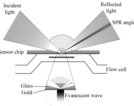
medium of lower refractive index. At a certain combination of angle of incidence and energy (wavelength), the incident light excites plasmons (electron charge density waves) in the gold film. As a result, a characteristic absorption of energy via the evanescent wave field occurs and SPR is seen as a dip in the intensity of the reflected light at a specific incident angle (the SPR angle). This angle varies as a function of the refractive index of the medium near the sensor surface, which changes when biomolecules attach to the surface. During interaction analysis, the changes in the SPR angle over time are displayed in a plot called a sensorgram. The unit for the SPR signal is the resonance unit (RU) and for ‘average’ proteins, one RU corresponds approximately to 1 picogram of material bound per square millimetre of surface area. The principles of SPR detection are illustrated in Figure 1.
Figure 1. The principle of surface plasmon resonance (SPR) detection. One interaction
partner is immobilized on the lower surface of the sensor chip to the dextran matrix attached to the gold layer. The analyte is passed over the surface under continuous flow conditions. The evanescent wave is created at the chip surface by the total internal reflection of incident light and propagates into the lower refractive index medium on the sample side of the interface, decaying exponentially in amplitude with distance from the surface. Polarised components of the evanescent wave field excite surface plasmons within the gold layer, enhancing the wave and causing a characteristic drop in the reflected light intensity, seen at a specific angle of reflected light, the SPR angle. Changes in refractive index close to the sensor surface caused by changes in mass concentration are detected as a shift in the SPR angle.
With increasing sensitivity in SPR experiments and a larger variety of applications, more interaction assays suffer from reduced accuracy because analyte concentrations or baseline stabilities are affected by non-specific interactions between the materials in solution and those that form the walls through which the solutions are guided. PEO surfactants are needed when the analyte, often a protein, is guided through the microfluidic system. Without surfactants, the protein will adsorb to PDMS and not reach the sensor chip. When the protein sample reaches the sensor chip the surfactants serve no further purpose. It is very important to understand and control the interactions of surfactants with the dextran matrix attached to the gold layer of the sensor chip. This interaction results in a shift of the SPR angle and might reduce the accuracy of the analyte-ligand interaction measurement.
1.3 The microfluidic system
Micro-fluidic devices are often used to lead microliter quantities of solvents to the sensor area. In Biacore instruments, a so-called integrated fluidic cartridge (IFC) is used for this purpose and this IFC is made of polydimethylsiloxane (PDMS), also known as silicone
rubber. A number of advantages of PDMS have made it one of the most widely used materials in the microfluidics community. PDMS is a relatively cheap material and it does not break easily like glass. The simple fabrication, optically transparency and rugged elastomeric properties makes PDMS a handy material to work with. Complex 3D structures and microchannel networks can be fabricated quickly by multilayer prototyping approaches. PDMS is also non-toxic and gas permeable. The transparency, however, is not perfect since PDMS has a small amount of fluorophores, which makes it difficult for example when analysing the quantity of fluorescence labelled proteins to PDMS.
The polymer backbones of polysiloxane [-Si(CH3)2-O-]n. is the same as glass like materials. It is the high flexibility around the O atom in the siloxane backbone, 135-180o, and the low intermolecular forces that make the polymers very flexible.
In silicone rubbers, organic groups are attached to the silicon atoms and methyl groups are the most abundant giving the name to PDMS. To create silicone rubber, some methyl groups are exchanged with vinyl or phenyl groups. Phenyl groups provide rubber like structures that are flexible at extreme low temperatures. It is the cross-linking abilities of the vinyl groups that provide the means to create rubber or solid structures.
Cured silicone rubber has a stabilized cross structure, which is non-soluble and stable at higher temperatures. The network polymer structure of PDMS is highly permeable for certain gasses and small molecules can easily diffuse into the bulk polymer [2]. This feature results in both advantages and disadvantages. One advantage is that the permeability can be used to apply solid-phase extraction on pharmaceuticals [3]. It has also been shown that the material can be used to extract matrix to remove trace organic compounds from solutions [4]. The easy diffusion of small molecules into PDMS is due to its large internal free volume and in contact with certain solvents the volume will increase [5]. The disadvantage of the permeability is that the absorption of small hydrophobic molecules from solution can affect interaction assays as it might affect the actual concentration of these small molecules in solution. Small molecules are typically used in drug screening studies.
PDMS surfaces are hydrophobic and it likes to stay that way. The bulk of silicone rubber contains small quantities of highly mobile low molecular weight chains and these PDMS
because of the high flexibility in the PDMS chains. Furthermore, hydrophilic silanol groups are formed during oxidation of PDMS. Two such silanol groups can form siloxane cross links by means of a condensation reaction. This oxidation process alters the surface of PDMS into a silica-like layer that is more hydrophilic and denser, thus acting as a diffusion barrier for adsorption of small molecules. The oxidized layer is brittle and will crack upon mechanical stress. Water is capable of breaking siloxane bonds by hydrolysis, especially at a pH lower than 2.5 or higher than 11. Alkali elements act as a catalyst for depolymerization. It has been observed for the IFC material that silica like structures is released when it is exposed to NaOH and that an opaque/white coating is formed on the surface [8].
Figure 2. The chemical structure of PDMS [9]. The polymer backbone consists of silicon
(grey) and oxide atoms (red). Two methyl groups are attached to each silicon atom.
Figure 3. Microchannel networks created in PDMS. A typical IFC consists of flow channels,
valves and a flow cell area. In the expanded view, the flow cell area is visible. Flow cells are formed when the IFC is docked to a sensor surface. Close around the flow cell area, valves are embedded in the flow channels and these valves are operated by applying pressured air to a thin PDMS membrane. These valves are used to control which solution passes through the flow cells.
1.4 Protein Adsorption
Proteins adsorb to most surfaces. The driving forces for adsorption are hydrophobic- and electrostatic interactions, dispersion forces (Van der Waal), and changes in the protein
structure [10]. Hydrophobic interactions are the main driving force thus proteins will adsorb to a hydrophobic surface, regardless of the other interactions involved. With the highly hydrophobic surface of PDMS, protein adsorption is a major concern in certain applications. On hydrophilic surfaces, protein adsorption is regulated by the interplay of electrostatic interactions and changes in the surface and proteins structure. Although electrostatic
interactions play a minor role in the affinity of proteins for surfaces, electrostatic interaction influence the kinetics of the adsorption process as it acts on a longer distances. Attached proteins will often optimize their interaction with the surface. This optimization often involves a rearrangement in the protein structure in order to increase the number of contact points. Hydrophobic interaction between the protein and the surface requires close contact between the two, which may be optimized by structural rearrangements in the protein [10]. This process can continue for up to a few days and is the reason why protein adsorption is regarded as an irreversible process. The only surfaces that prevent protein adsorption are surfaces that are hydrophilic and contain a large degree of mobility (entropy). These surfaces typically contain hydrophilic chains that stick into solution. When proteins creep into the polymer layer, this mobility (entropy) is reduced and thus opposes the interaction.
Hydrophilic polymers are often based on poly-ethylene-oxide PEO (-CH2CH2O-)n, also called polyethylene glycol (PEG), and polysaccharides such as dextran. Hydrophilic polymers can be adsorbed, grafted, or embedded in PDMS. Biacore sensor surfaces often contain a coating with dextran. The efficacy of grafted polymers in reducing protein adsorption primarily depends on two characteristics: grafting density and the extension in solution. As a general trend, protein adsorption reduces with increasing grafting density and increasing length of the polymer chain. When the separation distance between two polymers is smaller than twice the radius of gyration the polymers are the most effective because the chains can stretch out into solution in a so-called brush conformation [10]. If the density is too low with a thin brush, large proteins can accumulate at the outer edges due to long range dispersion forces [10]. Higher grafting densities is also a problem since it might even invoke a reverse effect as proteins that creep into the polymer coating can adsorb with an even higher affinity than to un-coated surfaces. Logically, this effect occurs more readily for smaller proteins than for larger ones. There is an optimum when it comes to the length of the polymer as well. Too long polymer chains will probably end up in a tangled structure with low entropy that might even trap proteins.
2 MODIFYING PDMS
2.1 Dynamic coating with surfactants
Detergents belong to a class of compounds called surfactants. The term is derived from SURFace ACTive AgeNT. Surfactants are compounds that contain both a hydrophilic and a hydrophobic segment. They reduce interfacial surface tension in mixtures by adsorbing to interfaces [11]. Non-ionic detergents, as polyoxyethylene glycols, are characterized by uncharged hydrophilic head groups[11]. These detergents are mild and non-denaturing because they disrupt protein-lipid and lipid-lipid interactions rather than protein-protein interactions [11]. Micellization are small molecular aggregates which form readily in aqueous solution by spontaneous self-association or self-assembly of certain amphiphilic molecules, like surfactants [12]. The process is driven by hydrophobic interactions. In solution, water molecules arrange in a hydrogen bonding network. When introducing non-polar groups, the network is disrupted and the water molecules order themselves around the non-polar entity to satisfy hydrogen bonds [11]. To decrease the unfavourable decrease in entropy in the bulk water phase, the non-polar groups self-associate and reduce the total water-accessible surface of the complex relative to the monodisperse state [11]. The forces that hold amphiphilic molecules together arise from weaker van der Waals, hydrophobic, hydrogen-bonding and screened electrostatic interactions. Consequently micelles are very sensitive to the solutions condition. Increased temperature and addition of salt favours micelle formation [11]. The detergent monomers within the micelle constantly and rapidly exchange with free ones in solution. A number of parameters are used to characterize surfactants and their ability to form micelles.
2.1.1 HLB
Hydrophilic-Lipophilic Balance (HLB) is the total effect of hydrophilic- and the hydrophobic groups. The HLB is defined by a scale from 0 to 40, and the value is based on the molecular structure. Low HLB value, in general <10, indicates that a detergent has a low solubility in water while a HLB number between 10 and 20 indicates good water solubility [11]. For simple, single-chain detergents, HLB can be determined by the following equation [11]:
HLB = 7 + m * Hh + n * Hl
m - Number of hydrophilic groups in the molecule Hh - Value of the hydrophilic groups
n - Number of lipophilic groups in the molecule Hl - Value of the lipophilic groups [13].
2.1.2 CMC
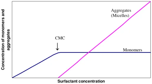
At low concentrations most of the surfactants in solution are isolated monomers. The moment when the monomer concentration can not increase further is called the critical aggregation
concentration (CAC) or more commonly the critical micelle concentration (CMC). Further
addition of detergent above the CMC will results in formation of more micelles, more or less without changing the monomer concentration [12]. CMC and the concentration of monomers and micelles are illustrated in Figure 4. In practise, the CMC does not occur at a single concentration, but rather over a narrow concentration range [11].
Surfactant concentration C o n c e n tr a ti o n o f m o n o m e rs a n d a g g re g a te s
Figure 4. Monomer and micelle concentrations as a function of the total surfactant
concentration.
Another physical property of micelle is the cloud point. Micelle formation is favoured by increased temperature. Rapid micelle growth along with inter-micellar attraction is likely to result in the formation of large particles that can precipitate out of solution, thus causing turbidity [11]. The temperatures were non-ionic surfactant solution separates into a detergent rich phase and a detergent poor phase is called the cloud point [11]. This is a reversible process upon cooling. The numbers of detergent monomers present within a micelle is called the aggregation number. Surfactants with smaller aggregation numbers tend to form more spherical micelles while detergents with larger aggregation numbers tend to form ellipsoid shaped micelles [11].
2.2 Physical properties of PEO based surfactants; P20, Pluronic F-127 and Brij 35
When surfactants attach to surfaces, the hydrophobic tails will form a brush-like structure on the surface thereby preventing proteins from adsorption. In the present study, three surfactants are investigated that have a hydrophilic portion that consists of polyethyleneoxide, namely P20, Pluronic F-127 and Brij 35. A short description of each surfactant is given below and a number of the physical properties of these three surfactants are collected in Table 1.
2.2.1 Polyoxyethylene (20) sorbitan monolaurate (P20)
Polyoxyethylene (20) sorbitan monolaurate (P20), commercially known as Tween, is both stable and relative non-toxic. The length of the PEO chain distinguishes P20 from the other members in Tween. In P20, 20 ethyleneoxide monomers are divided over four branches. P20 is used as surfactant at Biacore and is known to bind to dextran coated sensor chips in a concentration dependent manner. Thus below its CMC, variation in P20 concentrations are visible in the SPR response.
CMC
↓
MonomersAggregates (Micelles)
Figure 5. Chemical structure of P20 [14].
2.2.2 Pluronic F-127
Pluronic F-127 is a relative large non-ionic surfactant that is relatively non-toxic [15]. It is a bi-functional block copolymer surfactant with two 96-unit hydrophilic PEO chains
surrounding one 69-unit hydrophobic polypropyleneoxide (PPO) chain [16]. The polyethyleneoxide content is about 70 wt% [17].
H(OCH2CH2)96-(OCHCH2)69-(OCH2CH2)96OH │
CH3 Figure 6. Chemical structure of Pluronic F-127
2.2.3 Brij 35
Polyoxyethyleneglycol dodecyl ether or 23 Lauryl ether, commercially known as Brij 35, is about the same size as P20. The hydrophobic segment is of similar size and structure, but Brij 35 has an unbranched hydrophilic PEO chain just like Pluronic F-127.
CH3(CH2)10CH2(OCH2CH2)23OH Figure 7. The chemical structure of Brij 35.
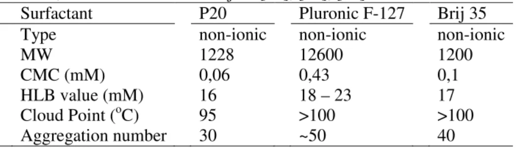
Table 1
Surfactant type, molecular weight (MW), CMC, HLB, Cloud point and aggregation number for P20, Pluronic F-127 and Brij 35 [18], [19], [20].
Surfactant P20 Pluronic F-127 Brij 35 Type non-ionic non-ionic non-ionic
MW 1228 12600 1200
CMC (mM) 0,06 0,43 0,1
HLB value (mM) 16 18 – 23 17 Cloud Point (oC) 95 >100 >100 Aggregation number 30 ~50 40
2.3 Protein repelling properties of surfactants
Pluronic F-127 is a relative large non-ionic surfactant with two 96-unit hydrophilic PEO chains surrounding one 69-unit hydrophobic polypropyleneoxide (PPO) chain. In P20, 20 ethyleneoxide monomers are divided over four branches. Brij 35 is about the same size as P20. The hydrophobic segment is of similar size and structure, but Brij 35 has an unbranched
hydrophilic PEO chain just like Pluronic F-127. Pluronic has the largest hydrophobic domain, about 11 times the size of the hydrophobic fragment of Brij 35 and P20, and should attaches quite stable to the hydrophobic surface of PDMS. On disadvantage of Pluronic might be that the hydrophilic PEO tails are too long while the hydrophobic domain is relatively large resulting in a tangled structure instead of the desired closely packed brush-like conformation. Brij 35 will probably attach as well as P20 because they have a similar hydrophobic part. The PEO chains in P20 might be too short to form an optimal surfactant brush. Compared to the branched PEO chains in P20, the unbranched and longer PEO chain in Brij, potentially allows for a higher packing density with longer PEO chains when attached to surfaces. These effects might reduce protein adsorption more effectively.
2.4 Chemical modifications of PDMS
To produce a protein repelling surface on PDMS, hydrophilic polymers, for example poly-ethyleneoxide can be adsorbed, grafted on or embedded in PDMS. For these types of surface modifications PDMS is often pre-treated, for example by oxidation or by extracting unbound, low molecular weight PDMS polymers from the PDMS bulk.
2.4.1 Oxidation, extraction and swelling of PDMS.
PDMS can be made more hydrophilic by oxidation. Hydrophilic silicondioxide (SiO2) and silanol (Si-OH) groups are formed when PDMS is exposed to air. The oxidation process can be accelerated by placing PDMS in an oxygen plasma chamber, by exposure to oxidizing solvents, or by air oxidation. PDMS can be kept hydrophilic by keeping the surface in contact with water or polar solvents [5]. In contact with air, the surface rearranges and new
hydrophobic groups are brought to the surface, since shorter PDMS chains move freely in the silicone rubber [6]. It has been reported that the contact angle of a water drop increases with more than 50o within 2 hours [22].
Table 2
Reported oxidation procedures for plasma-, solution- and air oxidation of PDMS. Oxidation Procedure
Plasma oxidation Oxygen pressure 1.1mbar, 200W, 15 s [21] Oxygen pressure 0.36mbar, 200W, 30 s [22] Solution oxidation H20/H2O2/HCl (5/1/1), 5min, rinse with water [23] Air oxidation Ozone flow (2 g/h) 15 min [24]
The rate of regeneration of the hydrophobic surface can be strongly decreased by extraction of un-cross-linked PDMS from the bulk polymer using organic solvents [5], [25]. Extraction is performed by immersing PDMS in solutions that cause it to swell extensively. Since PDMS is hydrophobic and non-polar it tends to swell in presence of non-polar solvents, for example hydrocarbons, toluene and chloroform [26]. The de-swelling and oxidation procedure has to be careful in order to avoid cracking of the surface [5], [25]. Cracking is also observed after rough oxidation, for example by using electrical arcing [24] and are the result of the
hydrophobic domain interacts with the hydrophobic PDMS bulk and the hydrophilic tails stick out into solution. Embedded hydrophilic polymers will not be attached as strong as a covalent bonding but it will improve the stability of the hydrophilic layer compared to that obtained by using surfactants.
2.4.3 Grafting
Silica surfaces can be activated for covalent attachment of polymers through silane chemistry. The frequently used activation of silica surfaces is performed by exposure to
aminopropyltriethoxysilane (APTES). This process can be performed in solution (see table 3) or in the gas phase by flowing APTES saturated air through oxidized PDMS fluidic channels. As the oxidized PDMS surfaces are unstable, they are often immersed in water before
subsequent chemical modifications are performed [11]. The amino derivatized surface can than be coated with polymers that have carboxylated end groups through carbodiimide (EDC/NHS) chemistry. APTES modified surfaces show slight deterioration after 10 days [13]. Using different cross-linkers it is possible to couple amine-functionalized PEO and perform two-step grafting of PEO polymers [11]. An appealing PEO grafting is to first link PEO to 3-trimethoxysilyl-propyl and methacrylate [29]. This resulted in a large polymer with a methacrylate backbone with both reactive silane groups and PEG chains which can be grafted on PDMS from a methanol solution in a one-step reaction. Also adsorbed multilayers of poly-anions and poly-cat ions (polyelectrolyte multilayers, PEMS) can be used to generate stable modified PDMS surfaces [30].
Table 3
Contact time, concentration, solvent, after-treatment and references for the activation of silica surfaces by exposure to APTES in solution.
Contact Conc. Solvent After Reference Immerse 4 h 20 mM Toluene Dry 1 h 21
Immerse 24 h 1% (v/v) Water 31
3 MATERIALS AND METHOD
3.1 Chemicals
HBS-N is an aqueous buffer containing 0.1 M HEPES and 1.5 M Sodiumchloride (NaCl), it is 0.2 µm filtered and a pH of 7.4. Surfactant containing buffers were made by dissolving 0.05 g of Pluronic F-127 (Sigma-Aldrich) or Brij 35 (Sigma-Aldrich,) respectively, in 100 ml HBS-N, resulting in 0.05% (w/v) concentration. 0.5 ml surfactant P20 (0.2 µm filtered 10% solution, Biacore) was added to 99.5 ml HBS-N, resulting in a final concentration of 0.05% (v/v). When coating PDMS the concentration of surfactants in the buffer is above the CMC value and the concentration of free monomers will remain stable. Hydrogen peroxide, 30%, reagent grade (H2O2) and Hydrochloric acid, 37%, reagent grade (HCl) was purchased from Sigma-Aldrich. H2O2 and HCl was mixed with MQ water (1:1:5) to obtain the solution for oxidation of PDMS. After dilution H2O2 had a final concentration of 6% and the
concentration of HCl was 7.4%. The peroxide solution was used within 8 hours. BIAdesorb1 0.5% (w/v) sodium dodecyl sulphate (SDS) (D1) and BIAdesorb2 50 mM Glycine pH 9.5 (D2) from Biacore were used for cleaning the flow system.
3.2 Proteins
To quantify protein adsorption, fluorescein isothiocynate (FITC) labelled proteins were used. FITC has a molecular weight of 389.38 g/mol, an extinction coefficient of 72000 M-1 cm-1, at 549 nm in aqueous buffer pH 8, and the excitation/emission wavelength is 541/572 nm [32]. When labelling antibodies (IgG), IgG was dissolved in 2.5 mL sodium carbonate buffer (0.1 M, pH 9) to a final protein concentration of 5 mg/mL. 250 µL freshly prepared FITC (1 mg/mL FITC in 0.1 M sodium carbonate buffer, pH 9) was added. The reaction mixture was incubated in the dark at 4 oC over night. The buffer was changed to PBS (0.138 M NaCl, 0.0027 KCl, pH 7.4) on a PD-10 gel filtration column after the reaction [33]. The final
concentration of FITC-IgG was 1 mg/mL, as determined spectroscopically using an extinction coefficient of 80000 M-1cm-1 at 495 nm and assuming that IgG has a molecular weight of 150 kD. For this concentration measurement, FITC-IgG was dissolved in 1% SDS with 0.1 M NaOH. Albumin, Fluorescein isothiocyanate Conjugate human (FITC-Albumin), (Bovine serum albumin, BSA) was purchased from Sigma-Aldrich and used without further treatment. The molecular weight of Albumin is 66 kDa [34]. FITC-Albumin was dissolved in HBS-N buffer, with or without surfactant, to a final protein concentration of 0.1 mg/ml. To avoid loss of fluorescence the sample was wrapped in foil during and between experiments and kept in the fridge when not used. Unless stated otherwise, the same protein solution was used for the replicate experiments.
3.3 Infra red spectra of PDMS surfaces and modifies PDMS surfaces
Infra red spectra of PDMS surfaces and modified PDMS surfaces were taken using an attenuated total reflection Fourier transform infra-red (ATR FT-IR) spectroscope (Spectrum one Perkin Elmer). For measurements on coated PDMS sheets, PDMS was immersed 60 minutes in buffer solutions containing the surfactants, in a volume ratio of 0.05%. New tubes were used. When the surfactants were analysed, Brij 35 and Pluronic were solids and P20 was in a 10% (v/v) solution.
3.4 Interaction of surfactants with dextran
Biacore®T100 was used to establish possible interactions of P20, Pluronic F-127 and Brij 35 with dextran, as present on CM5 sensor chips. A new Sensor Chip CM5 (Certified, series S) was used. The various surfactants dissolved in HBS-N buffer to a volume ratio were injected in Biacore T100 and their binding to CM5 sensor surfaces was evaluated. Each surfactant containing buffer solution was injected for 20 minutes followed by two hour dissociation while HBS-N is flowing through the flow cells. All flow rates are 10 µl/min.
Each surfactant is injected six times followed by 5 equilibration cycles. Also 20 equilibration cycles were run prior to the first injection of surfactant containing solution.
After each cycle, the system was washed by injecting Desorb1 and Desorb2 for 5 minutes each.
3.5 Flow system
For this study, Biacore developed two flow systems, one made of Polyetheretherkelon
surface modification with techniques that require a larger surfaces area such as FTIR and XPS analysis. Flat PDMS sheets (70x34mm2), polymerized on a polystyrene template, and were pressed against the flow cell structures with two clamps to create flow cells. These two clamps were in place at least 5 minutes before the experiment to make sure that sealed micro-channels were formed. The in- and outlets of the flow cells were connected to stainless steel pins, which in turn, were connected to tubes (orange/yellow tubes, ID 0.51 mm and wall 0.85 mm (PharMed)). Solutions were injected through the tubes and flow cells using a peristaltic pump (Ismatec pump IPN-24) and the flow rate in all experiments was 30µl/min.
To avoid carry over effects by contaminated tubes and flow cells, the flow system was rinsed with D1, D2, ethanol 70% and MQ before use. Furthermore, D1, D2 and MQ were flown for a minimum of 10 minutes, respectively, to clean the flow cells and the tubes before and after each experiment. A new PDMS sheet was used for each experiment and inserted after the washing step. New PDMS sheets were rinsed with MQ before use.
Figure 8. Flow system. Flow cell structures are shown on top, the side-view of the flow
system is shown in the middle and openings to the flow cell in- and outlets are shown in the bottom figure. All dimensions are in mm.
The flow cell made of PEEK was used for all experiments with FITC-Albumin and for the oxidation experiment with various contact time for the oxidation solution, seen in figure 17. For all remaining experiments with IgG the flow cell made of PMMA was used.
3.6 Quantification of adsorbed proteins to PDMS
Adsorption of FITC-labelled proteins to PDMS was quantified by measuring the fluorescence intensities by using a fluorescence microscope. To be able to compare experimental results from fluorescence measurements, the method has to be reproducible. Therefore, images were
taken directly after experiments. Images of the various flow channels were taken at
approximately the same position, relative to the channels in- and outlets. An average of two locations in the channel was used to determine the amount of adsorbed proteins. It was important to avoid taking pictures close to the beginning or the end of the flow channel as protein tends to accumulate in those areas. In some experiment almost no protein adsorbed to PDMS. In these experiments the channel had to be placed in position in the microscope by first using visible light to see the tracks in PDMS from the flow cell walls before changing to fluorescent detection. Fluorescent images were obtained by using a Nikon ECLIPSE E600 fluorescent microscope, 10x objective with a 100 W mercury lamp. A filter (EX 450 – 490 DM 505 BA 502 B-2A) was used. All fluorescent images were taken with a Nikon digital camera, cool pix 950, with a 1:2.6 – 4 and 7 – 21 mm lens. Nikon MDC Lens 0.82-0.29x was used as the adaptor. The images had an identical exposure time 1” and 3.7 zoom. The
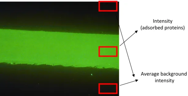
fluorescent intensities were quantified by Image-Pro Express Version 4.0. This software was used to calculate the average intensities of pixels that were selected by placing a rectangular frame in the image. To reduce variation due to an intensity gradient in the image, only the right side of the image was analysed, both for the channel and the background, as shown in figure 9. A final adjustment of the position was made to achieve the lowest variation in intensities of the selected pixels. To quantify the fluorescence intensity that originates from absorbed proteins, the average background intensity was subtracted from the intensity
measured in the flow cell area. In experiments were the effect of surface coating with various surfactants are evaluated, at least one flow cell contained surfactant-free equilibration and sample solutions. Fluorescence signals from these flow cells reflect the absorbed amount of proteins to untreated PDMS. Fluorescence intensities from treated PDMS surfaces are presented relative to those from untreated PDMS.
Figure 9. Fluorescence image of PDMS sheet. A strong fluorescence signal was observed in
the flow cell area after exposure to 1 mg/ml FITC-IgG. Fluorescence intensity of adsorbed proteins was quantified by subtracting the average intensity per pixel outside the flow cell area from the average pixel intensity in the flow cell area.
Average background intensity Intensity (adsorbed proteins)
intensity within the flow cell area represent the quantity of proteins that absorb after oxidizing PDMS. In these experiments, a batch of PDMS sheets was used that had an intrinsic
fluorescence intensity per pixel of 5 and this value was subtracted from all measured fluorescence intensities.
When quantifying the fluorescence from proteins adsorbed to PDMS after various washing procedures, the intensity from the flow cell area was divided with the intensity from the non-washed surface of PDMS sheet. The average intrinsic intensity from each PDMS sheet was subtracted from the signal of both the channel and the untreated PDMS. During washing, proteins released from the walls of the flow cell and adsorbed to PDMS. Therefore, only half of the channel was placed in protein sample solution. To account for the fluorescence signal that originates from protein adsorption during the wash procedure, the intensity from the untreated half of the channel was subtracted from the intensity of the channel that was exposed to the sample solution.
3.7 Dynamic- and pre-coating of PDMS
In dynamic coating the surfactant was added to both the equilibrium- and sample solution. When pre-coating PDMS, the surfactant was only added to the buffer in the equilibrium step, i.e., before protein containing samples were injected in the flow system. In both dynamic- and pre-coating the PDMS surface was equilibrated with various buffer solutions for 5 or 60 minutes, respectively. In dynamic coating experiments, FITC labelled protein [0.1 mg/ml] was dissolved in the same buffer as used in the equilibration step. In pre-coating experiments, the protein was dissolved in HBS-N buffer. Sample solutions were flown over PDMS surfaces for 5 minutes, followed by 5 minutes flow of HBS-N to wash out the sample before
fluorescence analysis. After the washing procedure, air was flown over the surface for 5 minutes. One channel was only flown with HBS-N buffer without any protein sample during all experiments and served as a blank to make it possible to subtract the intrinsic fluorescence signal of the PDMS sheets. The channel that was equilibrated with HBS-N and flown with protein dissolved in HBS-N was used as a reference of the protein adsorption in the absence of surfactants. The order of the channels was kept the same during all the replicates to
minimize possible cross contamination between experiment due to contamination of tubes and the flow cell.
To examine the stability of the surfactant-coated PDMS surfaces, PDMS was pre-coated with the various surfactant buffers for 60 minutes, followed by a 60 minutes wash of surfactant-free buffer before injecting the protein sample for 5 minutes. After the sample solution the PDMS surface was washed again with surfactant-free buffer for 5 minutes. New tubes were used in experiments where the equilibrium time was 60 minutes.
Table 4
The buffer and the time for equilibrium, protein sample injection and buffer wash in dynamic coating of PDMS surfaces.
Equilibration Sample Wash
Buffer Time (min) Buffer Time (min) Buffer Time (min)
HBS-N 5 Blank 5 HBS-N 5
HBS-N 5 HBS-N 5 HBS-N 5
HBS-P20 5 HBS-P20 5 HBS-N 5
HBS-Pluronic 5 HBS-Pluronic 5 HBS-N 5
Table 5
The buffer and the time for Equilibrium time, protein sample injection and buffer wash in pre-coating of PDMS surfaces.
Eq Sample Wash
Buffer Time (min) Buffer Time (min) Buffer Time (min)
HBS-N 5 Blank 5 HBS-N 5 HBS-N 5 HBS-N 5 HBS-N 5 HBS-P20 5 HBS-N 5 HBS-N 5 HBS-Pluronic F-127 5 HBS-N 5 HBS-N 5 HBS-Brij 35 5 HBS-N 5 HBS-N 5 3.8 Oxidation of PDMS
A peroxide solution, MQ/H2O2/HCl (5:1:1), was flown over PDMS surfaces for various times. After oxidation, the PDMS sheet was flushed with MQ and placed in a HBS-N bath for 5 minutes, followed by a bath in sample solution of FITC-Albumin (0.1 mg/ml) dissolved in HBS-N for 5 minutes. Finally, PDMS was placed in HBS-N for 5 minutes again to remove superfluous sample solution. To quantify the fluorescence intensity, the signal in the oxidized channel was compared with that of the untreated surroundings. The intrinsic fluorescence signal of PDMS was measured by leaving a part of the PDMS sheet out of contact with oxidation and sample solution. The stability of the oxidized PDMS was analysed by exposing the surface to a flow of HBS-N during various time, see table 7, before placing PDMS in the protein sample and HBS-N baths. To make the results comparable with those obtained directly after oxidation of PDMS, the sheets were placed in protein sample and HBS-N for 5 minutes, respectively. The same protein sample was used. For these stability studies, 30 minutes of oxidation time was chosen since it gave satisfying result in an acceptable time period.
Table 6
Contact time for oxidation, HBS-N and protein sample
Eq Wash 1 Sample Wash 2
Solution Time (min) Buffer Time (min) Buffer Time (min) Buffer Time (min)
ox 1 HBS-N 5 HBS-N 5 HBS-N 5 ox 5 HBS-N 5 HBS-N 5 HBS-N 5 ox 10 HBS-N 5 HBS-N 5 HBS-N 5 ox 30 HBS-N 5 HBS-N 5 HBS-N 5 ox 60 HBS-N 5 HBS-N 5 HBS-N 5 Table 7
Equilibrium time for oxidation and wash-time when examining the stability of PDMS oxidation.
Eq Wash 1 Sample Wash 2
Solution Time (min) Buffer Time Buffer Time (min) Buffer Time (min)
3.9 Removing adsorbed proteins from PDMS
The PDMS sheet was placed in sample solution of FITC-Albumin dissolved in HBS-N (0.1 mg/ml) for 5 minutes followed by 5 minutes HBS-N bath. After the protein adsorbed to PDMS, various solutions were flown over the surface for a total time of 40 minutes, and the PDMS was analysed by fluorescence microscopy. For oxidation, the peroxide solution of MQ/H2O2/HCl (5:1:1) was used.
Table 8
The injection time of the various solutions used to remove proteins adsorbed to PDMS. Injected solutions
Wash solution 1 Time (min) Wash solution 2 Time (min)
HBS-N 40
Desorb 1 20 Desorb 2 20
Desorb 1 20 HBS-N 20
ox solution 5 HBS-N 35
4 RESULTS AND DISCUSSION
4.1 Dynamic coating of PDMS
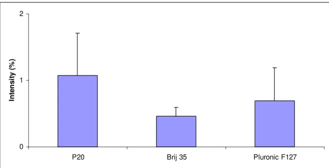
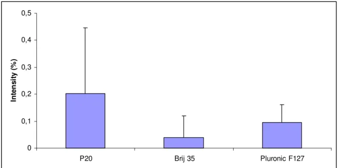
The calculated intensities were assumed to be proportional to the amount of adsorbed protein. FITC-Albumin, dissolved in surfactant free buffer, with surfactant free buffer during the equilibrium steps was used as a reference and reflects the adsorbed amount of protein in the absence of surfactant. The intensities are presented as the ratio (%) between the fluorescence intensity of proteins dissolved in surfactant containing and surfactant free buffer as shown in Figures 10 and 11 for adsorption of FITC-Albumin and FITC-IgG, respectively. In the experiment with FITC-Albumin, the reference dissolved in surfactant-free buffer gave a fluorescence signal that was four times lower compared to that of FITC-IgG. This can either be explained by higher absorbed amounts of FITC-IgG compared to FITC-Albumin or by the possibility that IgG is more densely labelled with FITC molecules than Albumin. Addition of surfactants in dynamic coating of PDMS reduced the fluorescence intensity from adsorbed FITC-Albumin to PDMS surface to about 1 %, as seen in Figure 10. When having Brij 35 present in equilibration and sample buffers, the lowest relative intensity was observed indicating that Brij 35 resulted in the best prevention against FITC-Albumin adsorption to PDMS. The same experiment was repeated with FITC-IgG and results are shown in Figure 11. In general, addition of surfactants to the equilibration and sample buffers resulted in a five times stronger reduction in the adsorbed amount compared to the reduction observed in experiments with FITC-Albumin. Also in the experiments with IgG, addition of Brij 35 yields the lowest average fluorescence intensity. The results from adsorbed Albumin and IgG both supported that Brij 35 is the best surfactant for dynamic coating of PDMS surfaces when reduced protein levels are required.
0 1 2 P20 Brij 35 Pluronic F127 In te n s it y ( % )
Figure 10. The average fluorescence intensities of FITC-Albumin adsorbed to PDMS surface
FITC-0 0,1 0,2 0,3 P20 Brij 35 Pluronic F127 In te n s it y ( % )
Figure 11. The average intensities of FITC-IgG adsorbed to PDMS surface presented as the
ratio (%) between the fluorescence intensities of FITC-IgG adsorbed from surfactant
containing and surfactant free buffer solutions, respectively. Error bars represent the standard deviation from 3 replicates.
4.2 Pre-coating of PDMS
In pre-coating of PDMS, the surfactants were only added to the buffer prior to sample injection and fluorescent signal arise from exposure of these coated surfaces to protein solutions dissolved in HBS-N. The results are presented as the ratio (%) between the fluorescence intensity of absorbed proteins after pre-coating with surfactant and surfactant free buffers. In the experiment with Albumin, the reference signal obtained from exposure of PDMS to proteins dissolved in surfactant-free buffer, had a fluorescence signal about six times lower when compared to IgG. After 5 minutes pre-coating of PDMS surface, the intensities were reduced to about 1%, which was about the same as when PDMS was dynamically coated. Pluronic F-127 resulted in the lowest fluorescence signal, as seen in Figure 12. The same experiment was repeated with FITC-IgG were Brij tended to reduce adsorption of protein to PDMS best, as seen in Figure 13. The tubes used in the IgG
experiment had been used often and probably contained a lot of fluorescent protein, resulting in the big variation of the fluorescence intensity. Moreover, it is likely that part of the
fluorescence signal arises because proteins desorb from the tubes and adsorb to the PDMS sheets during equilibration, which can affect the outcome of the results.
0 1 2 P20 Brij 35 Pluronic F127 In te n s it y ( % )
Figure 12. The average intensities of FITC-Albumin adsorbed to PDMS surfaces, presented
as the ratio (%) between the fluorescence intensities of adsorbed FITC-Albumin after pre-coating with surfactant containing and surfactant free buffer solutions, respectively. Error bars represent the standard deviation from 3 replicates
0 0,1 0,2 0,3 0,4 0,5 P20 Brij 35 Pluronic F127 In te n s it y ( % )
Figure 13. The average intensities of FITC-IgG adsorbed to PDMS surface presented as the
ratio (%) between the fluorescence intensities of adsorbed FITC-IgG after pre-coating with surfactant containing and surfactant free buffer solutions, respectively. Error bars represent the standard deviation from 4 replicates
To examine the stability of the surfactant-coated PDMS surfaces in more detail, surfactant buffers were flown over PDMS for 60 minutes followed by surfactant-free buffer wash for 60
most stable surfactant yielding the lowest fluorescence signal, close to the intrinsic fluorescence signal from PDMS.
0 20 40 60 80 100 P20 Brij 35 Pluronic F127 In te n s it y ( % )
Figure 14 The average intensities of FITC-Albumin adsorbed to PDMS surfaces presented as
the ratio (%) between the fluorescence intensities of adsorbed FITC-Albumin after 60 minute pre-coating with surfactant containing and surfactant free buffer solutions, respectively. After pre-coating the PDMS surfaces was washed with HBS-N for 60 minutes. Error bars represent the standard deviation from 3 replicates
4.3 Dynamic coating versus Pre-coating
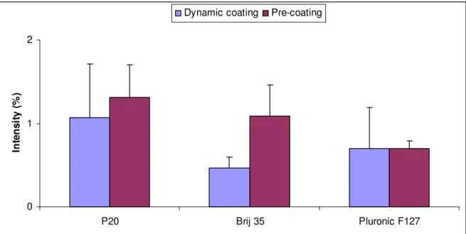
Dynamic- and pre-coating of PDMS with 5 minutes of equilibrium time with FITC-Albumin were carried out and analysed during the same day, which made the results comparable, as seen in Figure 15. Brij 35 and Pluronic F-127 tend to be more preferable than P20. Addition of surfactant in the sample did not remarkable reduce the adsorption, except when Brij 35 was added. 0 1 2 P20 Brij 35 Pluronic F127 In te n s it y ( % )
Dynamic coating Pre-coating
Figure 15. The average intensities of FITC-Albumin adsorbed to PDMS surface when
equilibrium time. All values are relative to the average intensities of FITC-Albumin adsorbed to PDMS surface when surfactant free buffers are used.
In conclusion, it is seen that surfaces pre-coated with Pluronic are relatively stable and prevents protein adsorption to the same extend compared to having Pluronic present in the sample buffer. Brij 35 is most effective in preventing protein adsorption but this coating is the least stable and its protein repelling property is gone after 1 hour of flowing surfactant free running buffer through the flow cell.
4.4 Oxidation of PDMS
The average intensities of FITC-Albumin adsorbed to PDMS after oxidation presented as the decrease in fluorescence signal (%) from adsorbed protein relative to that of untreated
surfaces and results are presented in Figure 16. Oxidation of PDMS with peroxide solution started to give a significant reduction in protein adsorption after oxidizing for 5 minutes and continues to yield lower adsorbed amounts oxidation times are increased up to one hour. After one hour, the intensity from adsorbed FITC-Albumin is about 10% compared adsorption to the non-oxidized PDMS surface. The largest difference in adsorption of FITC-Albumin is seen between 5 and 30 minutes of oxidation. Therefore, 30 minutes of oxidation time was chosen to study the stability of oxidized PDMS surfaces.
0 25 50 75 100
1 min 5 min 10 min 30 min 60 min
In te n s it y ( % )
Figure 16. The average intensities from FITC-Albumin adsorbed to PDMS surface after
oxidation of PDMS, using various contact times for the oxidation solution MQ/H2O2/HCl (5:1:1). The intensity is presented as the signal from adsorbed FITC-Albumin to oxidized PDMS relative to that of non-treated surfaces. Error bars represent the standard deviation from two replicates.
0 5 10 15 20 5 min 30 min 2 h 6 h 24 h In te n s it y ( % )
Figure 17. The average intensity from FITC-Albumin adsorbed to PDMS after 30 minutes of
oxidation and followed by a flown of HBS-N for various times prior to injecting the protein sample solution. The intensity is presented as the fluorescence signal from adsorbed FITC-Albumin to oxidized PDMS relative to that of non-treated surfaces. Error bars represent the standard deviation from tree replicates.
4.5 Removing adsorbed proteins from PDMS
Figure 18 illustrates the intensity of adsorbed FITC-Albumin after various washing combinations. The fluorescence intensities are presented as the ratio (%) between the
intensities after and before washing. Intensity caused by released protein from the walls of the flow cell during the wash and the intrinsic intensity of PDMS sheets were subtracted.
Injection of D1 followed by D2 for 20 minutes respectively or 5 minutes of oxidation solution prior to 35 minutes flow of HBS-N resulted in the lowest intensity from adsorbed proteins to PDMS. Oxidizing is very efficient in removing adsorbed proteins from tubes. It was revealed in the experiments where PDMS surface was oxidized to create a more hydrophilic PDMS surface layer. After about 10 to 20 minutes of equilibrium of the oxidation solution green fluid came out from the system when using old tubes. As seen in the results, oxidizing also is efficient in removing adsorbed proteins from PDMS surface.
These different washing procedures decreased the signal to about 15 % of the untreated PDMS in sample solution. Wash with only HBS-N buffer decrease the signal to about 60 %.
0 25 50 75 100 HB S-N 40 min D1 2 0 m in, D 2 20 min D1 2 0 m in, H BS-N 20 min ox 5 min , HBS -N 3 5 m in ox 2 0 m in, H BS-N 20 min In te n s it y ( % )
Figure 18. The average intensities (%) from FITC-Albumin adsorbed to PDMS after flown of
different washing solutions for 40 minutes.
4.6 Infra red Spectra of PDMS surfaces and modifies PDMS surfaces
Infra red spectra of PDMS, Pluronic and PDMS, coated with Pluronic are shown in Figure 19. Coatings with other surfactants Brij 35 and P20 were also measured but did not result in a significant difference compared to untreated PDMS. Most likely, these surfactants were washed away before the FTIR measurements were performed. The spectrum of Pluronic has a strong band around 1100 cm-1, representing the C-O-C stretching of PEO chains. This strong absorption band is visible in the spectrum of Pluronic coated PDMS as an increase in its shoulder at 1100 cm-1. Between 1200 and 1400 cm-1, ether-CH2 bending modes are visible for Pluronic resulting in a small top at 1400 cm-1 for PDMS coated with Pluronic. CH2 stretch vibrations from PEO are observed at 2900 cm-1, and for Pluronic coated PDMS an absorption band is clearly visible in this region. Assignments of chemical structures to IR absorption bands of PEO coated PDMS surfaces are based on results published by Makamba et al [28].
-0.02 0.18 0.38 0.58 0.78 0.98 1.18 1.38 700 1200 1700 2200 2700 3200 3700 wavelength (cm-1) Abs PDMS Pluronics PDMS+pluronics
Figure 19. Infra red spectra of PDMS, Pluronic127, and PDMS coated with Pluronic dissolved in buffer (0.05% (w/v), 60 minutes).
PDMS has its typical two strong absorption bands between 700 and 1100 cm-1.
4.7 Interaction of surfactants and dextran
Surfactants dissolved in HBS-N buffer to a volume ratio of 0.05% were injected in Biacore T100 and its binding to CM5 sensor surfaces was evaluated. Each surfactant containing buffer solution was injected for 20 minutes followed by two hour dissociation while HBS-N is flowing through the flow cells. After each cycle, the system was washed with a 5 minute injections of Desorb 1 and 2.
Due to long dissociation times and thorough washing of the system, a stable baseline was obtained that typically had a small negative slope of about 1 RU during the 150 minute experiment. After injecting various surfactant containing buffers, the baseline for the next cycle was not significantly affected meaning that no surfactants remained bound to the sensor chip at the end of each cycle. In Figure 20, the association phase when surfactant containing buffers are injected over the sensor chip is shown for six repetitive cycles. Injections of P20 and Brij 35 containing buffer solutions were reproducible. The injections of Pluronic containing buffer, however, showed an upward slope during the last 10 minutes of the first and second injection. Most likely, Pluronic slowly replaces material that was adsorbed to the tubing that subsequently binds to CM5 surfaces. After the 3rd injection, a reproducible response from Pluronic containing buffers was obtained and results from these experiments are used to quantify binding levels and dissociation constants.
0 50 100 150 200 250 300 350 400 0 300 600 900 1200 1500 Adjusted sensorgram RU R e s p o n s e ( 0 = b a s e li n e ) s Tim e Surfactant Brij Surfactant P20 Surfactant Pluronic
Figure 20. Sensorgram of 6 replicate injections of P20, Brij and Pluronic containing buffer,
volume ratio 0.05%, over CM5 sensor surfaces.
The binding of surfactants to carboxymethylated dextran, as present on CM5 sensor chips, was evaluated on its binding level and dynamics, characterized by its dissociation constant. With respect to the binding levels it can be seen that Pluronic binds to a lesser extend than P20 and Brij 35. The dissociation constant was somewhat below 1x10⁻³ s-1 for the surfactants P20 and Pluronic and roughly twice as fast for Brij 35. The dissociation rate constant was fitted using a single exponential decay function. From the total dissociation in two hours and the remaining amount of surfactant that is still bound to the sensor chip after two hours it can be seen that the dissociation behaviour is not well described by this single exponential function. For example for Pluronic, about 30% dissociates within the first minute while 60% is still bound after 2 hours. Even for P20, a substantial amount (30%) is still bound to the CM5 sensor chip after two hours. Brij 35 clearly dissociates fastest with both a relative high dissociation rate between 1 minute and 2 hours and a remaining quantity of 10% of its initial binding level after 2 hours.
Table 10
Binding level 10 s after the surfactant containing buffer is replaced by surfactant free buffer. Dissociation constant for P20, Brij 35, and Pluronic when interacting with carboxymethylated sensor chips (From 1 minute after injection end to two hours after injection end). The
response decrease, during the 2 hour dissociation phase, is given in the column “Dissociation” and the remaining binding level at the end of the dissociation phase is given in the last
column.
4.8 Challenges with the development of fluorescence- based quantification method
There were some challenges when developing the method used to quantify the adsorbed amount of fluorescence labelled proteins. The first difficulty was the contamination of the tubes since the wash procedure of D1, D2 and MQ did not work well. The increasing fluorescence signal after injection of protein-free solutions indicated that protein desorbed from the tubes and adsorbed to the PDMS sheets. This problem was discovered when searching the optimal time for the wash procedure. First the signal reduced with time but at one point the signal started to increase with time. When the system was left in circulation with MQ over night and the same PDMS was used in the morning the problem happened again, resulting in a strong fluorescent signal even though only MQ had flown over the PDMS. This was also a problem when trying to determine the optimal equilibration time since the attached protein released with time. Therefore new PDMS sheets were always used after the tubes were washed. New tubes were used in all experiments with equilibrium time longer than 5 minutes.
The unrestrained protein adsorption, caused by protein release from the system, was exposed when the results from dynamic coating with 5 minutes of equilibrium time was compared to the results from pre-coating with 60 minutes of equilibrium time. As seen in figure 20 the experiments gave the same results, with Brij 35 as surfactant with the smallest amount of adsorbed protein 0 1 2 3 4 5 6 7 P20 Brij 35 Pluronic F127 In te n s it y ( % )
Eq time: 5 min Eq time: 60 min
Figure 20. The average intensities of FITC-Albumin adsorbed to PDMS surface presented as
the ratio between HBS-N with added surfactant and surfactant free buffer (%) after 5 minutes of dynamic coating and 60 minutes of pre-coating. Error bars represent the standard deviation from 2 replicates in dynamic coating and 3 replicates in pre-coating.
In experiments where PDMS surface was pre-coated for 5 minutes with surfactants added to the buffer, prior to injection of FITC-Albumin dissolved in surfactant-free buffer, Pluronic yields the lowest fluorescence intensity. When the equilibrium time for the pre-coating of PDMS surface was prolonged to 60 minutes Brij 35 yields the lowest fluorescence intensity, just as in experiments when PDMS was dynamically coated. Tubes exposed to sample dissolved in surfactant free buffer in the pre-coating experiments probably contain plenty of
adsorbed proteins. Since proteins are released during the pre-coating the experiment will be equivalent with dynamic coating, where protein are dissolved in buffer with added surfactant. With 60 minutes of pre-coating behaving like dynamic coating the results can be compared with the data from the experiments with 5 minutes of dynamic coating, both revealing that Brij 35 is the surfactant that yields the lowest intensity when added to the protein sample solution.
When untreated protein was dissolved in surfactant free buffer, protein aggregates on PDMS could develop. Images of protein aggregates are illustrated in figure 21. The protein
aggregates seemed to clot the channels causing an increase of the average intensity. If possible, protein clotted areas of the channel were avoided when evaluating fluorescence intensities of images. When the protein was dissolved in buffer with added surfactant, aggregate formation of the protein was not a problem.
Figure 21. Fluorescence images of protein aggregates in a PDMS channel after rinsing with
FITC-labelled protein dissolved in surfactant free buffer.
The fluorescence intensity decreases with time, which was a problem when PDMS could not be analysed immediately. To examine for how long one could wait before analysing PDMS the intensities were measured immediately, 41 h and 67 h after the sample injection,
respectively. PDMS sheets were stored in the dark after the experiment. The intensities, as presented in Figure 22, were similar. This indicates that the fluorescence intensities from adsorbed proteins are relatively stable up to two days. After 67 h there was a slight loss of intensity, but the signal was still strong enough to give representative results.
Another problem with analysis of PDMS after a few days was that the tracks in the PDMS from the cell walls, that were used to put the channels in position, became indistinct. Without these tracks it was very difficult to take an image of the actually channel, and not its
surroundings. There were also some problems when the intensities were quantified in Image-Pro Express. PDMS itself has a small amount of fluorescence, which made it difficult when analysing fluorescence labelled proteins that yielded fluorescence with similar or lower intensity. To avoid this problem, a blank image of PDMS was measured and subtracted from the intensity from the adsorbed proteins.
The small amount of adsorbed protein also made it difficult to unambiguously determine the difference between the effects of surfactants in preventing protein to adsorb.
0,00 2,00 4,00 6,00 8,00 10,00 0 h 41 h 67 h In te n s it y
Figure 22. The average intensities of FITC-IgG adsorbed to PDMS surface from 5 channels
immediately, 41 h and 67 h after the injection, no blank is subtracted.
5 CONCLUSIONS
Protein adsorb strongly to the hydrophobic PDMS surface. All tree investigated surfactants; P20, Pluronic F-127 and Brij 35 considerably decreased protein adsorption when added to the buffer. When dynamically coating PDMS surfaces there was a clear indication that Brij 35 reduced protein adsorption best, both in the experiment with Albumin (99.5%) and IgG (99.9%). The average reduction in protein adsorption with Pluronic and P20 was about the same and amounted to ~99% for Albumin ~99.85% for IgG. When PDMS surfaces were pre-coated for 5 minutes Pluronic reduced FITC-Albumin adsorption best (99.3%) while P20 and Brij 35 reduced protein adsorption with ~99%. The same experiment was repeated with FITC-IgG were Brij tended to reduce adsorption of protein to PDMS best (99.95%), followed by Pluronic (~99.9%) and P20 (99.8%).
When examining the stability of the surfactant-coated PDMS surfaces after a 1 hour flow with surfactant free buffer solution through the flow cells, Brij 35 yielded the same fluorescence intensity as surfaces that were not pre-coated. The fluorescence signal was reduced to about 20 % when PDMS was pre-coated with P20. A 1 hour pre-coating with Pluronic, however, did not result in a significant binding of protein. The anchoring to the underlying surface is an important factor for protein repelling ability of PEG-containing layers [35]. When large proteins are present there is a risk for interfacial exchange, i.e., replacement of the adsorbed polymer layer by the protein [33]. Therefore, it is very important that the polymer layer is firmly attached to the hydrophobic surface. Pluronic F-127 has a 69-unit hydrophobic PPO chain, about 11 times the size of the hydrophobic fragment of Brij 35 and P20. The large PPO blocks of Pluronic provide a stable anchor to PDMS surfaces and were not washed away after a 1 hour buffer wash. It is not excluded that pre-coating with Pluronic for more than 5 minutes improves the protein repellent property by forming a more densely packed monolayer in which PEO chains adapt to a more brush-like conformation. Similar observations have been reported by Malmsten et al. [33] in which it was revealed that little or no interfacial
replacement by proteins occurs for Pluronic that was adsorbed to hydrophobic methylated silica surfaces. In the same study it was also shown that this Pluronic coating is comparable
with densely grafted PEO chains with respect to their protein repelling properties. In the experiments were the stability of the surfactants was examined Brij 35 had almost no protein repelling effect after 1 hour, indicating that Brij 35 is not firmly attached. Nevertheless, when using Brij 35 to create a PEG-containing layer it inhibited protein adsorption well when it is supplied continuously. Surprisingly, Brij desorbs faster from PDMS than P20 although the hydrophobic portion is similar and HLB value is only slightly higher. The unbranched PEO chains in Brij not only prevent proteins from adsorption better than P20 but also results in a more rapid desorption from PDMS surfaces.
The results from the stability of surfactant coating are strengthened by the study of surfactants binding to carboxymethylated dextran, as present on CM5 sensor chips. Although Pluronic binds to the dextran to a lesser extend, it binds strongly and dissociated very slowly. The dissociation constant was somewhat below 1x10⁻³ s-1 for the surfactants P20 and Pluronic and roughly twice as fast for Brij 35. Even for P20, a substantial amount (30%) is still bound to the CM5 sensor chip after two hours. Brij 35 clearly dissociates fastest and more completely. Oxidation of PDMS with peroxide solution started to give a significant reduction in protein adsorption after oxidizing for 5 minutes and continues to yield lower adsorbed amounts oxidation times are increased up to one hour. After one hour, the intensity from adsorbed FITC-Albumin is about 10% compared adsorption to the non-oxidized PDMS surface. The largest difference in adsorption of FITC-Albumin is seen between 5 and 30 minutes of oxidation. When PDMS was washed with surfactant-free buffer, after 30 minutes of oxidation, the fluorescence signal increased with wash-time. But even after 24 hours, adsorption of FITC-Albumin is considerably less compared to untreated PDMS surfaces. Compared to using PEO-based surfactants, however, the protein repelling effect of a
hydrophilic surfaces obtained by oxidation is a 10-fold lower. This finding supports the theory that not only the hydrophobicity of a surface is an important parameter to control protein adsorption but also the flexibility (entropy) of the surface.
In Biacore assays, proteins are removed from the flow system using an anionic detergent SDS flowed by a wash with a Glycine, pH 9.5solution. SDS is apparently also efficient in
removing detergents that were bound the dextran matrix on sensor chips. In this study, it is proven that oxidizing the flow system not only creates a more protein repellent PDMS surface but is also is as efficient as SDS/glycine and more effective then SDS in removing adsorbed proteins.
In summary, all three surfactants reduce protein adsorption to less than 1% of its adsorption to PDMS with Brij 35 providing the most effective and Pluronic 127 the most stable surface coating. These findings confirm the hypothesis that Brij can actually create a surface layer which is more effective than P20 and Pluronic because it can pack densely on PDMS surfaces. A surfactant free method to limit protein adsorption is provided by oxidizing the PDMS surface. Although less effective then the use of surfactants, it has the advantage that pre-adsorbed proteins are removed efficiently from the flow system during oxidation.
![Figure 2. The chemical structure of PDMS [9]. The polymer backbone consists of silicon (grey) and oxide atoms (red)](https://thumb-eu.123doks.com/thumbv2/5dokorg/4715669.124300/7.892.263.649.324.430/figure-chemical-structure-pdms-polymer-backbone-consists-silicon.webp)