Applying AUTOSAR in Practice
Available Development Tools and Migration Paths
Master Thesis, Computer Science
Authors:
Jesper Melin (jmn06007@student.mdh.se)
Daniel Boström (dbm06002@student.mdh.se)
Supervisor/Examiner:
Mats Björkman
mats.bjorkman@mdh.se
Abstract
With the increased use of Electronic Control Units (ECUs) in the automotive industry, the system creation and integration becomes progressively more complex. In order to manage this issue, the AUTomotive Open System Architecture (AUTOSAR) was initiated by several of the larger automotive companies and suppliers. Their goal was to create an architecture which will increase the reusability of software, integration of solutions from multiple suppliers and improve scalability. This thesis is made in collaboration with the company CrossControl and covers questions which are specific to their interests, features the AUTOSAR standard has to offer, evaluation of the use of development tools from different vendors, how migration is supported and how the standard affects the required hardware. Among our conclusions is that the AUTOSAR goals of decoupling software application components from the hardware is met to a high degree. Secondly even though file formats are standardized it is not a seamless integration between development tools. Finally, the choice of hardware is not only affected by properties of the standard, but the current versions of tools also limit the choices.
Keywords: AUTOSAR, development tools, migration, trade-offs, ArcCore, Arctic Studio, OpenSynergy, COQOS.
Acknowledgments
We want to thank the following people for their support and help during our thesis: Rikard Land at CrossControl for his experience and great help.
Michel Svenstam at ArcCore for his knowledge and help about AUTOSAR. Niclas Ericson at ArcCore for the help with Arctic Studio.
Jonas Carlsson at ArcCore for the help with hardware related issues. Carsten Krüger at OpenSynergy for his help with COQOS-tP.
Abbreviations and Terms
AAL Artop AUTOSAR Layer
AL Application Layer
API Application Programming Interface
ARXML AUTOSAR XML
ASIL Automotive Safety Integrity Level
AUTOSAR AUTomotive Open System Architecture
BSW Basic Software
CAN Controller Area Network
CanIf Can Interface
CanNm CAN Network Management
CanSm CAN Schedule Manager
CanTp CAN Transport Layer
CanTrcv CAN Transceiver
CDL Complex Driver Layer
COM Communication
DEM Diagnostics Event Manager
DET Development Error Tracer
DIO Digital Input Output
DLC Data Length Code
E/E Electrical and Electronics
EB Electrobit
ECI Embedded Card Interface
ECL Artop Eclipse Complementary Layer
ECU Electronic Control Unit
ECUAL ECU Abstraction Layer
EcuC ECU Configuration
ELF Executable and Linkable Format
FAQ Frequently Asked Questions
FIFO First In First Out
GCC GNU Compiler Collection
GDB GNU Debugger
GPL General Public License
GUI Graphical user interface
HMI Human Machine Interaction
HRH Hardware Receive Handle
HTH Hardware Transmit Handle
HW Hardware
I/O Input/Output
IDE Integrated development environment
ISO International Organization for Standardization
JDK Java Development Kit
JTAG Joint Test Action Group
LED Light-emitting diode
MCAL Microcontroller Abstraction Layer
Mcu Microcontroller
MISRA The Motor Industry Software Reliability Association
OEM Original Equipment Manufacturer
OMG Object Management Group
OS Operating System
PDU Protocol Data Unit
PduR Pdu Router
PWM Pulse-Width Modulation
RAM Random Access Memory
RTE Runtime Environment
SCHM BSW Scheduler module
SDG Special Data Group
SL Service Layer
SPEM Software Process Engineering meta-model
SPI Serial Peripheral Interface
SW Software
SWC Software Component
SWD Serial Wire Debug
TCP Transmission control protocol
UDP User Datagram protocol
UML Unified Modelling Language
VFB Virtual Functional Bus
XML eXtensible Markup Language
Table of Contents
1 Introduction ... 1 1.1 Background ... 1 1.2 High-level Questions... 1 1.3 Answers ... 3 1.4 Thesis outline... 3 1.5 Process steps ... 32 The AUTOSAR standard ... 4
2.1 Background ... 4
2.2 Purpose with AUTOSAR ... 4
2.3 Common applications using AUTOSAR ... 9
2.4 AUTOSAR architecture ... 10
2.5 Software components ... 13
2.6 Methodology ... 21
2.7 Trade-offs ... 23
3 Dependability and Safety ... 25
3.1 Critical systems ... 25
3.2 Dependability ... 25
3.3 AUTOSAR and Safety ... 26
4 Survey of Development tools for AUTOSAR ... 28
4.1 Tool vendors ... 28
4.2 Artop ... 34
5 Selection of Development Tools... 36
5.1 First iteration ... 36
5.2 Second iteration ... 39
5.3 Result from first and second iteration ... 40
6 Demonstrator ... 42
6.1 Requirements of the demonstrator ... 42
6.2 What we have done ... 42
6.3 Help from suppliers ... 43
6.4 Design decisions ... 44 6.5 Communication ... 45 6.6 Workflow ... 46 6.7 Equipment ... 47 6.8 Nodes ... 47 6.9 System ... 48 6.10 Topology cases ... 51
6.11 Mapping of groups to nodes ... 55
6.12 I/O Simulator ... 55
6.13 CAN communication with STM32 ... 60
6.14 CAN communication with COQOS-tP ... 60
6.15 Debugging ... 69
7 Evaluation ... 71
7.1 Hardware independence ... 71
7.2 Maturity of the tools ... 74
7.4 Trade-offs in practice ... 82
8 Lessons learned and Reflections ... 84
8.1 Lesson 1: The Workflow could be smoother ... 84
8.2 Lesson 2: The Learning curve is steep ... 84
8.3 Lesson 3: Sharing files between tools ... 88
8.4 Reflections on a good AUTOSAR development tool ... 90
8.5 Reflection on Configuration and Implementation ... 92
8.6 Reflection on simulation possibilities ... 93
8.7 Reflection on suitable CrossControl products to be used with AUTOSAR ... 93
9 Conclusions ... 95 9.1 The standard ... 95 9.2 The tools ... 95 9.3 Migration ... 95 9.4 Future work ... 95 10 References ... 96
11 Appendix 1: Demonstrator ARXML models ... 101
11.1 HeatRegulator.arxml ... 101 11.2 SeatHeater.arxml ... 102 11.3 SeatHeatingController.arxml ... 103 11.4 SeatSensor.arxml ... 106 11.5 DatatypesAndInterfaces.arxml ... 107 11.6 SeatHeaterComposition.arxml ... 109
12 Appendix 2: Demonstrator software components implementations ... 111
12.1 HeatRegulator.c ... 111
12.2 SeatHeater.c ... 112
12.3 SeatHeatingController.c ... 113
12.4 SeatSensor.c ... 116
13 Appendix 3: CAN sequence diagrams ... 118
13.1 Transmit request ... 118
13.2 Transmit confirmation ... 119
13.3 Receive indication ... 120
14 Appendix 4: IXXAT ECI state machine ... 121
15 Appendix 5: Linux I/O Simulator source code ... 122
16 Appendix 6: STM32 button source code ... 124
16.1 stm3210e_eval.h ... 124
16.2 stm3210e_eval.c ... 124
1
1 Introduction
Today’s automotive industry is faced with a growing demand for technical appliances and this requires an increased use of ECUs which is reflected in the complexity of the system. Traditionally, solutions have been specific for a certain platform or model and this structure is more becoming unmanageable and costly. Instead of making specific solutions a standardized future is the way to go. This increased complexity could be manageable and improved by a standardized architecture and the solution is AUTOSAR.
This thesis will present the key elements of the AUTOSAR standard and evaluate to what extent it holds true in practice by developing a demonstrator using AUTOSAR dedicated tools.
1.1 Background
AUTOSAR emerged as a solution for standardized automotive software in the automotive industry but has recently started to gain interest in other industries as well thanks to its many benefits. CrossControl is a company with a background in the forestry machine industry. They provide expertise and solutions to a broad range of industrial vehicle applications and business.
Since there is a reasonable chance future customers of CrossControl will inquire about AUTOSAR based solutions, one goal of this thesis is to research if and how AUTOSAR can be applied to CrossControl's current products.
1.2 High-level Questions
This thesis is made in collaboration with CrossControl and with their interest in AUTOSAR; some questions are therefore more related to their importance and others to persons who are interested to know more about the standard. Three different topics have been the centre for the question formulation: The Standard, Development Tools and Migration from existing solutions, see Figure 1.
Figure 1: The three main topics with subjets
Safety Simulation Trade-offs Market Workflow Pitfalls Benefits Specific interests The Standard Development Tools Migration
2 1.2.1 The Standard
These questions are formulated in order to answer questions related to the standard and what it is like to develop towards the standard.
Q1.1. What is the AUTOSAR standard and why is it created?
Q1.2. Is it manageable to understand the whole standard or are some parts addressed for certain roles?
Q1.3. What parts of the standard is good to know about depending on the user’s role? Q1.4. What is it like to develop towards the standard?
Q1.5. Has the development of the standard introduced any trade-offs? Q1.6. What are typical AUTOSAR applications?
Q1.7. How does the standard support simulation?
Q1.8. How does the standard support migration from existing solutions? Q1.9. How does the standard support reusability?
Q1.10. Is it possible to reuse software components?
Q1.11. Is it possible to reuse configuration of the Basic Software Modules? Q1.12. How does the standard address safety issues?
Q1.13. Does the standard propose something which in practice is limited? 1.2.2 Development Tools
These questions are asked in order to determine what it is like to work with development tools for AUTOSAR.
Q2.1. How does the maturity of the tools look like, are they established?
Q2.2. How is the workflow between tools from different vendors, encouraged or not recommended?
Q2.3. Is it possible to share and reuse configurations between tools from different vendors? Q2.4. Is it possible to share and reuse configurations between tools from the same vendor? Q2.5. Development tool toolchain, is complete better than divided?
Q2.6. How important is it that the development tools support the target hardware? 1.2.3 Migration from existing solutions
The following questions are formulated in order to answer questions related to migration from existing solutions to the AUTOSAR standard.
Q3.1. Why migrate to the AUTOSAR standard?
Q3.2. Are any of CrossControl’s products suitable to be used with the AUTOSAR standard? Q3.3. After a migration, how could the expected productivity and cost figures look like? Q3.4. Does a migration affect the requirements on the hardware?
Q3.5. Are there any major pitfalls while migrating? If so, how can they be avoided?
Q3.6. Is it possible to integrate the AUTOSAR methodology into an already existing workflow?
Q3.7. How does the learning curve look like?
Q3.8. What are the benefits with AUTOSAR compared to non-standard solutions? Q3.9. Is the development paradigm shifted from implementation towards configuration? Q3.10. After a migration, is most time spent on Configuration or Implementation?
3
1.3 Answers
Throughout this thesis, the questions will be answered using the following format:
1.4 Thesis outline
Chapter 2 gives an introduction to the AUTOSAR standard with the intention of familiarizing the reader with what AUTOSAR is about and its vocabulary which will be used throughout the report. Chapter 3 briefly touches upon dependability and safety aspects that are worth considering in AUTOSAR’s areas of use. Chapter 4 presents a number of tool suites discovered during the research phase and chapter 5 covers the method and the result of comparing and eventually selecting tool suites used in later chapters. Chapter 6 makes use of the selected tools in chapter 5 in order to realize a demonstrator which can be used to answer questions raised in the introduction. In chapter 7 an evaluation based on the experience gained realizing the demonstrator in chapter 6 is presented. Chapter 8 dives into lessons that were learned during this thesis and reflections that arose afterwards. Finally chapter 9 covers the conclusions that can be drawn based on the knowledge obtained from the different process steps involved in this thesis.
1.5 Process steps
A number of process steps were defined in a certain order according to Figure 2; these steps were required in order to be able to answer the formulated questions.
Figure 2: The thesis divided into several process steps.
Evaluation of the demonstrator (chapter 7)
Define and create the demonstrator (chapter 6)
Select tool vendors (chapter 5)
Survey in available development tools (chapter 4)
Learn about the AUTOSAR standard (chapter 2)
This answers QX.X “Question formulation”
4
2 The AUTOSAR standard
The following section will present the basics and fundamental parts of the AUTOSAR standard.
2.1 Background
Today’s vehicles that are rolling out from the factories are basically computers with wheels. A modern vehicle consists of approximately 50-60 ECUs and the numbers are increasing for each year [1]. Each unit is in charge of a specific functionality and they communicate with each other over some kind of bus, e.g. CAN, FlexRay, LIN etc. For each additional unit that is connected to the system, the system complexity increases. Applications and software must be configured for each system and with new hardware the applications must be rewritten each time to support any changes in the hardware. In order to handle this increased complexity, which would eventually become unmanageable, a handful of leading Original Equipment Manufacturers (OEM) and Tier 1 suppliers from the automotive industry, decided to work together to form a new standard that would serve as a platform for future vehicle applications, and their result is AUTOSAR[2].
The development of AUTOSAR is today a global cooperation between car manufacturers, suppliers and other companies from electronics, semiconductors and software industry. The cooperation started in 2003 with just a couple of the larger companies from the automotive industry and together they been developing a standardized software architecture for the automotive industry that is still being evolved. Together they have come up with their motto [2]:
“Cooperate on standards, compete on implementation”
This summarizes in a good way what their intention is. One important thing to remember is that AUTOSAR does not specify a specific implementation; it is up to the tool vendors and other companies to follow the AUTOSAR standard specifications and implement according to them.
2.2 Purpose with AUTOSAR
The development is moving from a hardware and component-driven process towards a process that is requirement and function-driven. The aim is not to optimize every single component, the future challenge for engineers is to optimize on a system level. In order to do so, a common platform is required that is scalable and supports exchangeable software modules. One of the fundamental ideas behind AUTOSAR is reusable Software Components (SWCs) that can deal with the increasing complexity today and in the future [2].
As mentioned earlier, software is tightly coupled with the ECU where it is going to be executed. If something is changed in the ECU, the software must be rewritten to suit with the hardware. It is problematic to buy software from one manufacturer and hardware from another, if they are not made to work with each other. Another example is for example one car manufacturer that has done all the work for one car in one of their production series, has to redo much work again to make the first system fit another car in a different production series. Depending on the manufacturer, models used and how variations are handled, this problem can be smaller or larger but the problem is still present in different scales.
The left side of Figure 3 shows the conventional integration between hardware and software. The figure represents the software tightly coupled for a specific hardware solution. Possible hardware
5 options could for example be changed architecture of the processor or different types of peripherals. These types of specific solutions might be better for certain situations, but with the increasing complexity it will probably fail in the long run. What the automotive industry wants is to move from the left side version and end up at the right side version instead. The applications are decoupled from the hardware (hardware independent) thanks to standardized interfaces that AUTOSAR can offer. With a standardized interface it would be possible to buy software and hardware from different manufacturers, and they would all work together. This would not be as smooth with the conventional solution.
Figure 3: AUTOSAR makes the application software independent from the hardware
Application software that supports the AUTOSAR standard will receive several benefits. The following examples are the driving forces why we need AUTOSAR as listed in [3]:
Manage increasing E/E complexity – Associated with growth in functional scope. Improve flexibility – More room for updates, upgrades and modifications. Improve scalability – The system can in a more graceful manner be enlarged. Improve quality and reliability – Proven software applications can be reused. Detection of errors in early design phases
2.2.1 Technical goals and objectives
Some of the primary goals for the AUTOSAR development may have already been mentioned, but this section will in short present the goals with AUTOSAR. According to their own website and the FAQs section[2], the primary goal is the standardization of basic system functions and functional interfaces, the capability to integrate exchange and relocate functions within a car network and substantially improve software updates/upgrades over the vehicle lifetime.
Some of these goals (mentioned below), will be tested in our demonstrator system to see to what extent they are fulfilled in practice with supported AUTOSAR tools.
This answers Q1.1 “What is the AUTOSAR standard and why is it created?”
AUTOSAR is standardized software architecture developed in cooperation between car manufacturers originally intended for the automotive industry but is steadily gaining interest from other industries as well. AUTOSAR was developed with the intention of being able to handle the increased complexity in today’s automotive industry and to decouple software from hardware.
6 The goals mentioned in the above can be extracted and pinpointed down to these points:
Modularity - This will enable “tailoring of software according to the individual requirements of electronic control units and their tasks.” [4]. This goal is achieved by introducing standardized interfaces and hardware abstraction.
Scalability – This will ensure “the adaptability of common software modules to different vehicle platforms to prohibit proliferation of software with similar functionality.” [4]. This goal can be achieved thanks to a combination of the other goals and the use of a standardized framework.
Transferability - Transferred functions will “optimize the use of resources available throughout a vehicle’s electronic architecture.” [4]. This is achieved by hardware abstraction; the software should be possible to place on any ECU in the system.
Re-usability – Reuse of functions will “help to improve product quality and reliability and to reinforce corporate brand image across product lines.” [4]This goal is achievable thanks to the object oriented system design. The software is designed as atomic components which should increase the reuse possibilities.
Similar and additional goals and objectives are these ones, as listed in [5]:
Implementation and standardization of basic system functions as an OEM wide “Standard Core“solution.
Integration of functional modules from multiple suppliers Maintainability throughout the whole “Product Life Cycle“ Increased use of “Commercial off the shelf hardware“ Software updates and upgrades over vehicle lifetime Consideration of availability and safety requirements Redundancy activation
7 2.2.2 Benefits suggested by the AUTOSAR Consortium
The AUTOSAR standard has many benefits to offer and several of them are stated on the official website for the Consortium. A summary of benefits are listed in Table 1 as listen in [2]:
General benefits
Increased re-use of software Increased design flexibility Clear design rules for integration
Reduction of costs for software development and service in the long term
OEM overlapping reuse of non-competitive software modules
Focus on protected, innovative and competitive functions
Specific benefits for OEMs
Functions of competitive nature can be developed separately
Later sharing of innovations is accessible Standardized conformance process
Specific benefits for suppliers
Reduction of version proliferation Development sharing among suppliers
Increase of efficiency in functional development New business models
Preparation for upcoming increase in software volume
Specific benefits for tool developers
Common interfaces with development processes
Seamless, manageable, task optimized (time dependent) tool landscape
Specific benefits for new market entrants
Transparent and defined interfaces enable new business models
Clear contractual task allocation and outsourcing of software-implementation accessible
Table 1: AUTOSAR Benefits
This answers Q3.1 ”Why migrate to the AUTOSAR standard?” and Q3.8 ”What are the benefits with AUTOSAR compared to non-standard solutions?”
If a system has an unnecessary high software-hardware dependency that is possible to avoid, had a different approach been considered, AUTOSAR could very well be the solution. In most cases benefits such as reusability between vendors and scalability outweighs the trade-offs which could be introduced but each system is different thus there is no one-answer-fits-all scenario.
8 2.2.3 Main topics of AUTOSAR
AUTOSAR is more than just a new standard how applications should be written. In order to fully handle the problems and offer a complete solution, the project is centered on three main topics, see Figure 4.
Figure 4: AUTOSAR main topics
These topics are first briefly described in the next three following sections, then as separate chapters (Architecture in section 2.4 , Methodology in chapter 2.6 and Application Interfaces which has no own section).
2.2.3.1 Architecture
The first topic handles the layered software architecture. It includes a complete stack of the Basic Software (BSW) and how the relationship looks like between these layers. In additional to the BSW layer, the AUTOSAR architecture also distinguishes (on the highest abstraction level) the Runtime Environment (RTE) and Application Layer. The BSW layer is divided into smaller layers; these will be presented in detail in section 2.4.1.
The reader who is interested about the layered software architecture, we recommend the following document [6].
2.2.3.2 Methodology
In order to exchange and combine SWCs from different manufacturers, a common methodology is necessary for some of the steps in the system development. It describes how the description templates should look like or other common formats that make a seamless configuration possible, between the different stages in an AUTOSAR development phase. So this topic in short manages the common formats that must be followed for a seamless design between different parts.
The methodology doesn’t define a precise order how every single step should be taken, it defines dependencies between work and result e.g. what artifacts is needed to finish activities.
To read more about this, we recommend the following document [7].
Architecture
Methodology
Application
9
2.2.3.3 Application interfaces
With the new release of AUTOSAR 4.0, the scope of standard is the following five domains [8]: Body and Comfort
Powertrain Chassis
Occupant and Pedestrian Safety HMI, Multimedia And Telematics
For each domain, there are a set of Standardized Application Interfaces that should be used to share content between SWCs. AUTOSAR does not specify the internal design of software applications; this opens the competitive window for developers. With a Standardized Application Interface, the exchange of data is clarified.
With common interfaces for specific domains, it is possible to exchange applications between different OEMs, suppliers etc. Thus, a cornerstone for reusability.
An example of a Standardized Application Interfaces for a Wiper/Washer component in the Body and Comfort Domain [9] can be seen in Table 2.
Component: Washer Component: Wiper
WshngReq1 (WashingRequest) WipgAutReq1 (WipingAutomaticRequest) Interfaces WshrSts1 (WasherStatus) WiprSts1 (WiperStatus)
WshrFldSts1 (WasherFluidStatus) WinWipgCmd1 (WindowWipingCommand) Table 2: Interfaces for Washer and Wiper components
These six interfaces are defined for the Body and Comfort domain, but you are however free to define your very own interfaces if you are creating a system that does not use any of these common functionalities or any widely required interfaces. They must however follow the standardized naming convention along with other rules, but that is something that the tools should take care of.
For further reading, we recommend [8]and the documents found at [10].
2.3 Common applications using AUTOSAR
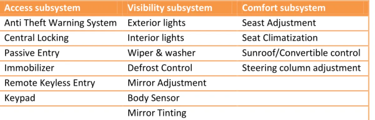
There are number of different applications or systems that could be realized using the AUTOSAR standard. We read the latest version (release 4.0) of the domain documents and summarized some of them (Table 3) which can be found in the documents for the different domains that are specified in the standard [11][12][13][14][15].
Access subsystem Visibility subsystem Comfort subsystem Anti Theft Warning System Exterior lights Seast Adjustment Central Locking Interior lights Seat Climatization
Passive Entry Wiper & washer Sunroof/Convertible control Immobilizer Defrost Control Steering column adjustment Remote Keyless Entry Mirror Adjustment
Keypad Body Sensor
Mirror Tinting
10 As staid, this is just a sample of all the applications or systems that could be found in the documents, but hopefully it gives a hint of what could be realized in AUTOSAR. There are no limitations for the behavior of the applications. An exception is applications that have requirements that might not be feasible to reach when following the AUTOSAR standard. These requirements could for example be timing, memory-usage etc.
2.4 AUTOSAR architecture
The AUTOSAR architecture is using a layered approach consisting of a total of three software layers running on top of a microcontroller (see Figure 5) [6]. These three layers are called, starting at the bottom, BSW, RTE and finally Application Layer (AL). An introduction to each layer will be presented below.
Applicat ion Layer
Runt ime Environment (RTE)
Basic Sof t ware (BSW)
Microcont roller
Figure 5: The AUTOSAR architecture.
2.4.1 Basic Software
While the BSW layer is a layer in itself, internally it consists of four sub-layers (see Figure 6). These sub-layers can be divided into functional groups (stacks), such as memory and I/O, vertically spanning the entire BSW layer.
2.4.1.1 Microcontroller Abstraction Layer
The Microcontroller Abstraction Layer (MCAL) is located at the very bottom of the BSW layer. MCAL uses its internal software drivers to directly communicate with the microcontroller. These drivers
This answers Q1.6 “What are typical AUTOSAR applications?”
Frequently used car functionality is suitable for the AUTOSAR standard. The scope of the standard is not limited to only the automotive industry since the implementation of a SWC’s behavior is not restricted.
11 include: memory-, communication- and I/O drivers. The task of the layer is to make layers above it microcontroller independent.
When the MCAL is implemented it is microcontroller dependent but provides a standardized- and microcontroller independent interface upwards in the stack thus fulfilling its purpose.
Applicat ion Layer
Runt ime Environment (RTE)
Microcont roller Complex Drivers Layer (CDL) Services Layer (SL)
ECU Abstraction Layer (ECUAL)
Microcontroller Abstraction Layer (MCAL)
Figure 6: The AUTOSAR architecture including BSW sub-layers.
2.4.1.2 ECU Abstraction Layer
Located on top of the MCAL is the ECU Abstraction Layer (ECUAL). Internally it has drivers for external devices and uses the interface defined by the MCAL to access drivers at the lowest level. Layers higher up in the stack can use the provided API to gain access to devices and peripherals without having to know anything about the hardware, for example, whether or not a device is located internally or externally, what the microcontroller interface looks like etc. All this is part of the ECUAL’s task i.e. to make upper layers independent of how the ECU is structured.
During implementation the ECUAL is microcontroller independent thanks to the MCAL but dependent on the ECU hardware; layers interfacing the ECUAL are no longer dependent on either of them.
2.4.1.3 Complex Drivers Layer
The Complex Drivers Layer (CDL) is one of two layers spanning the entire BSW layer. Typically this layer is used to integrate special purpose functionality and functionality currently being migrated from a previous system. Since this is the only layer between the microcontroller and the RTE, drivers for devices with strict timing constraints can benefit from being placed in the CDL as the multi-layered parts of the BSW layer is likely to introduce overhead due to additional layers and standardization [16]. Drivers for devices not compliant with AUTOSAR can also be put here.
Whether or not application, microcontroller or ECU hardware dependencies exist while implementing and afterwards for upper layers interfacing the CDL layer depends on the functionality one is going to integrate.
12
2.4.1.4 Services Layer
The top sub-layer in the BSW layer is called Services Layer (SL). Along with operating system functionality the SL provides a collection of managers such as: memory-, network-, and ECU state management. This is also where diagnostic services reside.
As parts of the SL span the entire BSW layer it is not entirely microcontroller and ECU hardware dependent during implementation; its interface towards the RTE is however.
2.4.2 Runtime Environment
The RTE is the layer between the application layer and the BSW layer. It provides the application software with services from the service layer. All communication between SWCs, either on the same ECU or different ones, or services are done via the RTE. The main task of the RTE is to make the layer above and below it completely independent of each other. In other words, SWCs running on an ECU have no idea what the ECU looks like hence a SWC will be able to run on different looking ECUs without any modifications.
Logically the RTE can be seen as two sub-parts realizing different SWC functionality [17]: Communication
Scheduling
When the RTE is implemented it is ECU and application dependent; thus it is specifically generated for each different looking ECU. Instead of adapting SWCs to different ECUs that is what is done with the RTE, this way SWCs can stay the same thus accomplishing the set out task.
2.4.3 Application Layer
The AL differs in two major aspects from the rest of the layers; it is component based and not standardized [8]. SWCs are such a key part of this layer and AUTOSAR and have as a result been awarded a dedicated section (see Software components). Looking at the RTE and the BSW layers there are lengthy standards documents specifying how they shall look and behave. Creating SWCs and the behavior in the AL can be done freely according to what a particular vendor wants. One restriction though is that all communication with other components, whether it is intra- or inter-communication, has to be achieved in a standardized way by using the RTE.
Since the RTE makes layers above it independent of hardware such as the ECU and the microcontroller the AL is, apart from a few cases, only dependent on the RTE [6]. For example the sensor-actuator SWC is dependent on the hardware but SWCs communicating with it are not.
This answers Q1.8 “How does the standard support migration from existing solutions?”
The introduction and creation of Complex Drivers in the AUTOSAR standard can be used to migrate existing solutions.
13
2.5 Software components
AUTOSAR uses its own notation for modeling applications. An application consists of one or more SWCs based in the Application layer. In order for SWCs to communicate with each other they use the virtual functional bus (VFB). From a SWC’s point of view all it sees is the VFB and not the hardware dependent BSW and the hardware itself; in reality this is provided by the RTE [18]. The VFB as a whole is implemented not only by the RTE but also by the BSW. Whether or not two interacting SWCs reside on the same ECU is not important, both are connected to the same VFB and don’t need to know where in fact the other one is located [19].
Automotive functionality can either be fitted into a single component or spread out in multiple components. Apart from the actual implementation of a component it is always accompanied with a formal SWC description. A SWC description includes among other things:
General characteristics o Name o Manufacturer Communication properties o PPorts o RPorts o Interfaces
Inner structure (composition) o Sub-components o Connections
Required hardware resources o Processing time o Scheduling o Memory
Having knowledge about hardware requirements for each SWC makes it easier to decide on what ECU a particular component should be placed. If you have the scenario where two manufacturers provide components of similar functionality but the slightly better one has a higher hardware resource demand, which would force you to add another ECU to your system, you would be able to make a decision at an early point on what to do. If you don’t have the ability to increase the number of ECUs in your system you are forced to go with the slightly poorer but less resource demanding component.
The center of attention when developing systems at the VFB level is its basic building blocks namely SWCs. A component has ports for which it uses to communicate with other components. Each port can only be assigned to one specific component. The complexity of the functionality implemented by a component can vary greatly so can the number of ports. AUTOSAR allows multiple instances of the
This answers to Q1.9 “How does the standard support reusability?” and Q1.10 “Is it possible to reuse software components?”
A consequence of the hardware independence in the Application Layer is improved reusability of SWCs. This is done by using a standardized architecture.
14 same component to exist; the same implementation but different memory spaces in order to store instance specific data.
2.5.1 Ports
There are two types of ports in AUTOSAR SWCs; a PPort provides data defined in the port-interface while an RPort instead requests data. For sender-receiver and client-server port-interfaces AUTOSAR service versions also exist.
2.5.2 Port-interfaces
AUTOSAR supports three types of port-interfaces: client-server, sender-receiver and calibration.
2.5.2.1 Client-server
The client-server pattern is well-known and commonly used. The server provides services while one or more clients may use its services to carry out tasks [20]. The client-server model defined in AUTOSAR is a simple n:1 (n ≥ 0 clients, 1 server) one. An operation invoked on a server uses arguments supplied by a client to perform the requested task, these argument types can either be of simple (bool) or more complex nature (array).
When a client wants to invoke an operation of a server’s interface a value for each operator parameter has to be provided. At a later point in time when a response is received it can either be a good or a bad one. There are a total of three possible responses:
Valid response, the server was able to execute the requested operation and values have been assigned to all parameters provided by the operation interface.
Infrastructural-error, a transmission to/from the server went wrong due to a broken bus [21]. For example an operation response never returned to the client resulting in a timeout on the client-side.
Application-error, something went wrong on the server-side while executing the operation invoked by a client.
As mentioned above only an n:1 client-server mechanism is supported by AUTOSAR. In more detail this means that any component acting as a client has to have an RPort connected to exactly one of a server’s PPorts; this PPort can however be connected to an arbitrary number of client RPorts. Then it is up to the implementation of the communication to make sure every response is transmitted to the correct client’s RPort. Since a component is not limited to one port or one port type, one and the same component can act as both a client and a server.
Limits exist on how clients may invoke operations on servers. Two concurrent invocations of the same operation on the same client RPort is not allowed; not until a response on the first invocation has been received, a good or a bad one, is it allowed to invoke the same operator again. Concurrent invocations of different operations are allowed on the same RPort but the VFB does not guarantee the ordering of the invocations i.e. the order in which the server sees the invocations or which order the responses from the server are received. The VFB is however required to enable a client to relate a response to a previous invocation.
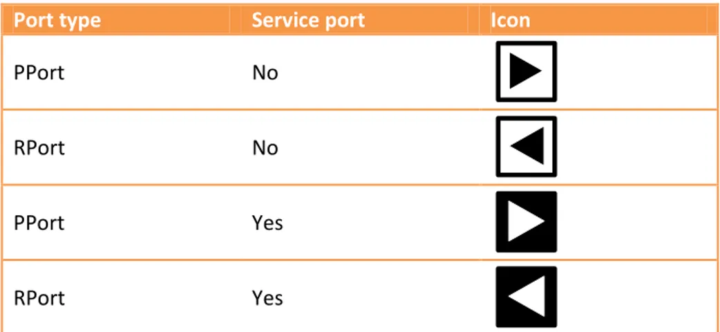
When Components are modeled the client-server interface has its own graphical representation (see Table 4).
15
Port type Service port Icon
PPort No
RPort No
PPort Yes
RPort Yes
Table 4: Graphical representation of client-server ports.
2.5.2.2 Sender-receiver
This way of communicating allows one receiver to get information from multiple senders or a sender to send information to an arbitrary number of receivers. What type of data-element is sent between a sender and a receiver can be just about anything, from a simple integer to a more complex one like an array for example. There are two ways for which data-elements can be provided by the sender; either “last-is-best” which means the last value made available by the sender is the current one while “queued” means values are stored in a queue of predefined size.
A sender is completely decoupled from any receivers, it has no idea how many (if any) receivers are using the values it is producing. It is however possible at configuration time to enable transmission acknowledgements if a sender wants to know if a transmission succeeded or not.
If the “queued” semantics is used the receiver consumes values from the queue in a FIFO-fashion. The queue is located on the receiver side of the connection, this is logical since consumable reads are taking place. If a queue is full and there are still new values to add a queue overflow will occur and the new values are discarded; whether or not the receiver is notified of these events can be set at configuration time.
Considering multiplicity of the sender-receiver port-interface there are different limitations depending on which semantics is used. In the case of “last-is-best”, only 1:n (1 sender, n ≥ 0 receivers) communication is possible. Whereas for the “queued” semantics both 1:n and n:1 (n ≥ 0 senders, 1 receiver) are possible. The latter is possible because multiple senders can add values to the queue of a single receiver. For “last-is-best” there is only one value and if there are multiple senders they would constantly overwrite each other’s values and there is no guarantee the receiver will be able to see all produced values.
The VFB supports filters; filters can be used to reject values not fulfilling the conditions of a filter. If a value is filtered out, the current value is not changed, in case of “last-is-best” or “queued”, it is not added to the queue.
When modeling SWCs the sender-receiver port interface is differentiated from the client-server interface by its own graphical notation (see Table 5).
16
Port type Service port Icon
PPort No
RPort No
PPort Yes
RPort Yes
Table 5: Graphical representation of sender-receiver ports. 2.5.2.2.1 Communication modes
Data reads and writes can be performed in two different ways, implicit or explicit. An implicit read means that a copy of the data is fetched before the start of the runnable (see Runnable entities) execution and is guaranteed to remain the same until the runnable terminates. Similarly for an implicit write data can be modified while a runnable is running and is not made available on the provider port for other SWCs to read until the runnable has terminated. In other words no explicit calls are made. On the contrary explicit reads and writes make API calls when they need to carry out the respective tasks; these API calls can be either blocking or non-blocking depending on the port- and runnable configurations.
2.5.2.3 Calibration
Port-based calibration requires a component in need of calibration abilities to define an RPort. The RPort is connected via a connector to a PPort on a calibration parameter component; this is called public calibration parameters since the parameters are visible on the VFB. The PPort of a calibration parameter component can provide multiple SWCs with the same set of parameter values. But the case where components have their own calibration parameter component also exists.
SWC calibration can also be done in private internally within a composition; thus called private calibration. A sub-component is also known as a prototype and there are two types of calibration prototypes; either shared between other prototypes or individually assigned to prototypes in need of their own calibration parameter values.
As in the case for client-server and sender-receiver port interfaces calibration port interfaces have their own graphical notation as well (see Table 6).
Port type Service port Icon
PPort No
RPort No
17 2.5.3 Connectors
In order to connect two ports a so called assembly-connector is used. A connector can be used to both connect prototypes within a composed component as well as connect different component to each other.
2.5.4 Composed and atomic components
A SWC can be built up by multiple sub-components and connectors. As mentioned earlier, in AUTOSAR these sub-components are also called prototypes. This type of component is defined as a composition of interconnected prototypes. A composed component is like any other component from the outside and it can be used to create hierarchical systems. An atomic component on the other hand cannot be divided into smaller components.
2.5.5 Component types
In AUTOSAR there are seven types of components; a brief overview is presented below.
2.5.5.1 Application software component
An application SWC implements either an entire application or just a part of one. The component is atomic and has access to all AUTOSAR communication types and services. The sensor-actuator component, which will be described shortly, is used to handle all interaction with sensors and actuators.
2.5.5.2 Sensor-actuator software component
All sensor and actuator related tasks are handled by the atomic sensor-actuator SWC. It is sensor and actuator specific and makes it possible for other SWCs to use a sensor or actuator by providing an interface independent of the actual hardware. In order to do this it needs access to the ECUAL interface.
2.5.5.3 Calibration parameter component
Its only task is to provide values for calibrating all connected components. If all connected components are not located on the same ECU the calibration parameter component has to be duplicated and placed on every ECU having at least one other component needing it. A calibration parameter component does not have any internal behavior as oppose to “normal” SWC.
2.5.5.4 Composition
The composition type has already been described; one thing that can be added though is that it can use all AUTOSAR communication types and services.
2.5.5.5 Service component
A service component in AUTOSAR is standardized and uses standardized interfaces to provide services. Direct access to BSW is needed in order to provide these services to other components.
2.5.5.6 ECU-abstraction component
When the sensor-actuator component was described above it was mentioned that it interacted with the ECUAL. To be more precise, it is provided access to I/O via a client-server PPort on an ECU-abstraction component. This ECU-ECU-abstraction component has the ability to interact with other BSW.
2.5.5.7 Complex device driver component
The final component type is the complex device driver component and it is a generalization of the ECU-abstraction component. It can communicate directly with other BSW and is typically used for
18 applications with critical resource demands. Software residing here is not as tightly coupled to the AUTOSAR standard as everything else but the interface towards the so-called “AUTOSAR world” does have to follow the AUTOSAR port and interface specifications [6].
2.5.6 Runnable entities
A runnable entity (runnable in short) is the smallest code fragment inside a SWC. It is these runnables that are mapped to OS tasks and will execute the behavior of the SWC. This is needed since the SWCs themselves are not aware of the BSW layer where all the OS functionality such as tasks resides. A SWC can have multiple runnables which may be required to carry out certain tasks.
Two main categories of runnables exist, the determining factors of which category a runnable is placed is described below.
Category 1 is where all runnables without any waiting points (non-blocking) are placed; in other words the runnables can with certainty be considered to terminate in finite time. Within category 1 there are two sub-categories; 1A which is only allowed to use an implicitly defined APIs and 1B which is an extension to 1A allowing it to also use explicit APIs and make use of functionality provided by a server.
Category 2 comprises runnables with at least one waiting point. With a few exceptions all runnables of category 2 strictly have to be mapped to an extended task since it is the only task type providing the waiting state [9].
Events of the RTE simply called RTEEvents (see Table 7) trigger the execution of the runnables; this is done by either activating them or waking them up.
Name Communication restriction Description
TimingEvent None Triggers a runnable
periodically.
DataReceiveEvent Sender-receiver only Triggers a runnable when new data has arrived.
OperationInvokedEvent Client-server only
Triggers a runnable when a client wants to use one of its services provided on a PPort. AsynchronousServerCallReturnsEvent Client-server only
Triggers a runnable when an asynchronous call has returned.
Table 7: A subset of all the available RTEEvents defined in AUTOSAR; for a complete list look in [17].
2.5.6.1 Mapping to OS tasks
Mapping runnables to OS tasks is not the easiest job. There are a lot of properties playing a part when determining which type of OS task is required for the runnable at hand. These are some properties to consider: placed is described below.
Runnables using an implicit API for reading and writing data cannot have any waiting points or infinite loops. In other words, runnables of category 1.
Runnables of category 1 can be mapped to either task type (basic and extended).
As already mentioned a runnable of category 2 normally needs to be mapped to an extended task. For example a synchronous server call will block until the server has completed its
19 execution resulting in a waiting point thus a category 2 runnable. The following exceptions exist:
o If no timeout monitoring is needed a runnable making a synchronous call can be mapped to a basic task.
o A basic task can also be used if the runnable of the invoked server is of category 1 and is invoked directly.
A couple of example scenarios can be used to illustrate the importance of some of the properties mentioned above.
2.5.6.1.1 Scenario 1
The following is given for this scenario: Category 1A runnable(s).
All communication is done with implicit reads and writes of data using the sender- receiver interface.
A TimingEvent is used to trigger the runnable. Mapping to one task only.
2.5.6.1.1.1 Basic task
If only one runnable exists it can be mapped to a basic task without any additional conditions. However if more than one runnable is present all of them have to be assigned the same cycle time and the sequence for which they will execute. See Figure 7 for an illustration.
20 2.5.6.1.1.2 Extended task
For the case in the basic task section where multiple runnables are used and no order of execution is provided an extended task will be used instead. This extended task will endlessly check for events such as OS alarms related to the different cycle times of the runnables in order to determine which runnable should be executing (see Figure 8).
Figure 8: Example of scenario 1 when a mapping to an extended task is required.
2.5.6.1.2 Scenario 2
The following is given for this scenario: Category 2 runnable(s).
Explicit sender-receiver communication
A DataReceivedEvent referenced by a waiting point.
When considering the normal case of this scenario the only possible task type to use is the extended task since a category 2 runnable is being handled. When an RTEEvent triggers the execution of the runnable it will eventually end up at the waiting point which will cause a block until data is received. Data reception is signaled by a DataReceivedEvent which will allow the runnable to continue execution.
Since there is no way of knowing for how long the runnable will remain in the blocking state each category 2 runnable is usually mapped to its own task (see Figure 9). Mapping two category 2 runnables to the same extended task could lead to serious time delays if one runnable comes out of blocking mode while the task is still waiting because the other runnable is blocked [17].
21 Figure 9: Example of a category 2 runnable mapped to its own extended task.
2.6 Methodology
In this section the AUTOSAR Methodology will be described in more detail. 2.6.1 Templates
Objects in AUTOSAR are described using different templates, which contains a collection of attributes that are necessary to describe a certain subject of AUTOSAR. Subjects could for example be ECUs, SWCs or the whole system. These templates are den specified using UML, which is based on the AUTOSAR UML Profile, described in [22].
2.6.2 Methodology steps
The methodology also describes sets of activities for the development of a system. There are four major activities and steps (Figure 10) that must be performed to generate the ECU Executable which will run on the ECU. Each activity is divided into smaller activities and this thesis will not describe each sub-activity, only one will be presented in detail (Configure System). The methodology does not describe a complete process; it does not define how many times these steps must be repeated.
Figure 10: Main steps
This answers Q1.11 “Is it possible to reuse configuration of the Basic Software Modules?”
22 2.6.3 SPEM
The AUTOSAR methodology is described with help from the Software Process Engineering meta-model (SPEM)[3], which is a standardized terminology used to describe processes. The standard is defined by the Object Management Group (OMG) consortium. Not the whole standard is used by the AUTOSAR methodology, just a small subset of SPEM is used and we will only present three of those modeling-elements. For a complete list and detailed description, we recommend [7][Methodology].
2.6.3.1 Work-product
The document shaped figure represents a so called <<Work-Product>>. That is a piece of information that is either consumed or produced by an activity. There are four specific <<Work-Product>> defined in the AUTOSAR methodology [7]:
XML-Document (may be one or several documents) c-Document (files containing sources written in C) Obj-Document (for object files)
h-Document (files that are containing header files includes by c-files)
2.6.3.2 Activity
The work-products just mention is consumed or produced by an <<Activity>>, which describes a piece of work that needs to be carried out. The name of the activity is written underneath the symbol. The role that is supposed to carry out the activity is not specified in the AUTOSAR methodology since it doesn’t define any roles.
2.6.3.3 Guidance
At last but not least, is the shape that is not exposed in the previous figure, the so called <<Guidance>>. In the AUTOSAR methodology, an <<Guidance>> is modeled to represent a tool that is needed to perform a certain activity.
2.6.4 Extract ECU specific information
We are only going to take a closer look at one of the activities shown in Figure 10 and that is the Extract ECU specific information activity. The rest of the activities are left unmentioned because the same work-flow is applied to those activities as well.
23 What we see in Figure 11 is a more detailed view of the second activity. As we can see there is one input to this activity, namely System Configuration Description. In reality there are more dependencies with other documents describing the system and the SWC implementation, but we have chosen to not go into further details since [7] already has a great in-depth explanation for those that are interested.
One of the shapes in Figure 10 where not present in the previous figure and that is the <<Guidance>>, in this case called AUTOSAR ECU Configuration Extractor. Based on the input to the activity, the tool will produce the output.
In order to handle the activities, developers of AUTOSAR software need help from tools to grasp all the documents and dependencies. So as a part of our research, we have searched for vendors that offer AUTOSAR development or configuration tools. The ones we have found and examined are presented in section 0.
2.7 Trade-offs
During the research and reading, numerous papers and articles have been encountered which propose possible benefits the AUTOSAR standard has to offer. Yet the AUTOSAR coin has two sides; benefits and trade-offs. Papers or articles that discuss the trade-offs that implementers of AUTOSAR compliant software and solutions must face is quite hard to find. There are a few papers that mention possible trade-offs and their effect [23], but almost none that is dedicated to just trade-offs. It might be the case that the standard is relatively new and therefore have not been exposed for in depth inspection by third party groups (researchers etc).
Since there are quite few articles written about the technical trade-offs that the AUTOSAR standard suffers from, it’s hard to point at certain criteria.
We can at least expect that there should be trade-offs present when try to expose the standard for certain situations, which could indicate an ineffective system. Our intention is to test these plausible trade-offs, such as memory consumption, timing and execution overhead by exposing the system for certain tests. See section 7.4 for the evaluation done as a part of this thesis.
2.7.1 Memory
With the introduction of a complete architecture stack, there is likely to be an increase of memory use since an Operating System is needed and communication between SWCs always has to go via the RTE. This architecture stack is needed to decouple the software from the hardware, but the question to what price. We expect to see a larger increase of memory usage in simpler AUTOSAR solutions compared to non-AUTOSAR solutions. There might not be necessary to have a complete operating system in these cases, thus, non-AUTOSAR solutions are expected to be smaller.
This answers Q3.6 “Is it possible to integrate the AUTOSAR methodology into an already existing workflow?“
Rather than defining a workflow, the methodology describes work packages and actions. The input which is required to perform a certain activity in order to generate a certain output is defined. This should make it possible to integrate the AUTOSAR methodology into existing ones.
24 2.7.2 Execution Overhead
Since the software is not allowed to make direct calls to the hardware, there are likely to be an increase of the overhead in the system. You are not allowed to read a specific port directly; lower layers must handle this in order to decouple the software from the hardware. We are very confident that this will cause extra over overhead compared to a “barebone” solution where direct calls to the hardware is allowed. The question is the magnitude of this overhead compared to the “barebone” solution. It should be possible to save some execution time by using the Complex Driver module in the BSW, since there is room to do non-AUTOSAR standard calls here.
2.7.3 Migration to AUTOSAR
When introducing a new standard there are likely to be problems and child disease that could be considered as trade-offs. Companies may already have optimized procedures when a new system for the automotive industry is going to be developed. Introduce a new standardized way to develop systems into an already working system is prone to suffer from various problems.
The standard tries to comprehend this possible problem by presenting a methodology that should be followed, previously presented in section 2.6.
Developers and implementers need to understand the standard in order to create systems that are compliant with other AUTOSAR solutions. A complete understanding of the whole standard might not be necessary, but some of the fundamental parts, such as the architecture. The problems a migration could create could be interpreted as a kind of trade-off.
25
3 Dependability and Safety
This section will briefly present dependability, safety and at the end how AUTOSAR addresses safety issues.
3.1 Critical systems
Users of commonly used desktop software know that there is a chance that the software can sometime fail. That is why for example we save this document several times while we are writing, and keep backups saved in different locations. A failure in the software can often be disturbing and hours of work can disappear in a wink of an eye, but in the long term, it doesn’t lead to serious damage.
However, there are other types of systems were failures in the software doesn’t just lead to inconvenience, it can lead to, for example: physical damage, huge economical loss or human lives at stake. These systems that people and business depend on are called critical systems. If these systems fail to deliver the expected service then the result may be serious problems and economic loss, as mention earlier.
In [20], three different main types of critical systems are mentioned:
1. Safety-critical systems – Failure may result in injury, loss of life or serious environmental damage.
2. Mission-critical systems – Some kind of goal-directed activity may fail. This could for example be a navigational system for a spacecraft.
3. Business-critical systems – Failure may result in very high economical cost for the business using the system. An accounting system in a bank is a good example.
Here will only focus on safety-critical systems since this is strongly connected with the automotive industry, were AUTOSAR has its origin. Cars are for example dependent on safety-critical systems, such as airbag or brake systems.
3.2 Dependability
The most important property of a critical system is its dependability and there are several reasons [20]:
1. “Systems that are unreliable, unsafe or insecure are often rejected by their users”. If the customers cannot trust the software, they will refuse to use it and may also reject other products from the same company.
2. “System failure cost may be enormous”.
The cost of the control system is nothing compared to the cost of a system failure. 3. “Untrustworthy systems may cause information loss”.
It is not just expensive to collect data, but also to maintain it. The data itself is often much more valuable than the system it is processed on. To guard the data against corruption, much effort and money is spent on e.g. duplication.
A high cost is always involved when talking about critical systems. Therefore, only well-known and proven development techniques and methods are typically used. It is better to stay conservative rather than embrace new methods that might be more effective, but without long-term testing.
26 3.2.1 Principles
There are four different principles related to dependability [20]:
1. Availability – The ability of the system to deliver services when requested. 2. Reliability – The ability of the system to deliver services as specified. 3. Safety – The ability of the system to operate without catastrophic failure.
4. Security – The ability of the system to protect itself against accidental or deliberate intrusion.
Figure 12: Dependability and its sub categories
One key part in safety is that no matter how good the implementation quality is, it cannot be considered to be safe if the specifications are incorrect. So it is very important that the specifications are formulated correctly, with formal notation or with words.
3.3 AUTOSAR and Safety
Previous releases of the AUTOSAR standard (R3.1 and older) had no explicit focus on safety and security [24]. With the latest release (R4.0) functional safety concepts has been introduced to support safety related applications. Some of these new concepts are [8][24]:
Memory partitioning – Applications are separated from each other to avoid corruption of data.
Support for dual microcontroller architecture – The aim is to detect faults in one core by a secondary unit.
Safe end-to-end communication – Aims to provide the applications means to send data and detect errors during transmission.
Since the latest revision is so new, most development tools are still adapted for the R3.1 standard as seen in Table 9, Table 10 and Table 11.
3.3.1 Standards
The introduction of these new concepts is however not enough to develop safe applications. Standards such as IEC-61508, ISO-15998 and ISO-26262 must be followed before the applications can be considered as sufficiently safe. ISO-26262 is an adoption of IEC-61508 for the automotive industry and defines different levels of Automotive Safety Integrity Levels (ASILs) [25]. Depending on the ASIL level set for the application to be developed, certain activities must be performed based on the ASIL level.
To use the generated code one of the following options are available in a safety related project:
Dependability
27 Qualified – Tools which generate code based on input must be qualified. It means that the tool and the generation of code have gone through extensive testing and evaluation, before the generator can be qualified.
Tool proven-in-use – The latest versions of tools are never used. Instead, versions of the tools which have been used by many for a sufficiently long period of time and are well documented. The vendor also must have systematic procedures to handle errors reports and correct these or document the errors.
Review of generated code – The generated code from the tools must go through the same rigorous review process as the newly developed code.
The AUTOSAR Methodology is designed to use tools for certain activities. Many of these tools generate code based on information found in the descriptions files for example SWCs. None of the tools we have examined are qualified and the two used during the thesis are not stable enough to be considered as proven-in-use. This is not so surprising since safety concepts have been recently introduced in R4.
This answers Q1.12 “How does the standard address safety issues?”
In the latest revision of the AUTOSAR standard (R4), concepts for functional safety have been introduced. The AUTOSAR standard is young and the tools are still under development.


![Table 7: A subset of all the available RTEEvents defined in AUTOSAR; for a complete list look in [17]](https://thumb-eu.123doks.com/thumbv2/5dokorg/4826525.130107/24.892.95.796.645.877/table-subset-available-rteevents-defined-autosar-complete-list.webp)


