Use Case Notation
Ingemar Drott
Department of Computer Science
University of Skövde, Box 408
S-541 28 Skövde, SWEDEN
Use Case Notation
Submitted by Ingemar Drott to the University of Skövde as a dissertation towards the degree of M.Sc. by examination in the Department of Computer Science.
October 2001
I certify that all material in this dissertation which is not my own work has been identified and that no material is included for which a degree has previously been conferred on me.
Abstract
UML and use case modeling have the last few years received much attention. Use cases are used to describe the functional requirements of a system and a use case diagram shows the relationships among use cases and actors within a system. The semantics of use case diagrams are, however, often unclear. The aim of this dissertation is to point out ambiguities and limited expressiveness present in the current use case notation of UML and to indicate in which directions remedies to these deficiencies may be sought.
Problems reported by researchers were identified and presented to a set of use case practitioners. Then a proposal of possible improvements of the use case notation, which should reduce the ambiguities and increase the expressiveness in the notation, was developed. To place some measurements on the value the proposal can have in practice, it was also presented to a set of practitioners.
The proposal provides a suggestion of how to model various tricky situations in a use case diagram. Furthermore, the dissertation gives insight on how the use case technique is used in practice. Practitioners argue that the use case specifications are more important than the use case diagrams. They also argue that the purpose of use case diagrams is to describe a system's main functionalities and not details, and that as few use case relationships as possible should be used in use case diagrams.
Key words: UML, use case, use case diagram, ambiguities, limited expressiveness,
1 Introduction ... 1
1.1 Aim and objectives... 2
1.2 Delimitations... 3
1.3 Research Approach ... 3
1.4 Outline of the report ... 5
2 Background... 7
2.1 The Unified Modeling Language ... 7
2.1.1 Descriptions of UML elements mentioned in the dissertation ... 11
2.1.1.1 Relationships ... 11
2.1.1.2 Extensibility mechanisms ... 12
2.1.1.3 Other mentioned elements ... 13
2.1.2 UML in systems development... 13
2.1.3 Use of UML... 15
2.1.3.1 The Rational Unified Process ... 15
2.1.3.2 The SELECT Perspective... 16
2.1.3.3 The ICONIX Unified Object Modeling Approach... 18
2.1.3.4 UML and business modeling... 20
2.2.2 Relationships between use cases ... 25
2.2.2.1 Use case generalization ... 26
2.2.2.2 Include relationships... 26
2.2.2.3 Extend relationships ... 27
2.2.3 Use case specifications... 28
2.2.4 Scenarios ... 30
2.3 Use case diagrams ... 31
3 Problems with the graphical use case notation ... 33
3.1 Ambiguities in the graphical use case notation... 34
3.1.1 The semantics of «include» is unclear ... 34
3.1.2 The semantics of «extend» cannot handle exceptions... 35
3.1.3 The semantics of «extend» cannot handle alternatives ... 36
3.1.4 Generalization between actors can cause redundancy ... 37
3.2 Limited expressiveness in the graphical use case notation ... 39
3.2.1 Long-range logical dependencies cannot be expressed... 39
3.2.2 System response to passive actors cannot be expressed... 40
3.2.3 Included use cases cannot be directly instantiated by actors... 41
3.2.4 Information about present expansions cannot be shown... 42
4.1 The respondents ... 47
4.2 Opinions about the unclear semantics of «include»... 49
4.3 Opinions about the handling of exceptions... 51
4.4 Opinions about the handling of alternatives ... 51
4.5 Opinions about possible redundancy between actors ... 53
4.6 Opinions about logical dependencies... 54
4.7 Opinions about system response to passive actors... 56
4.8 Opinions about instantiation of included use cases ... 57
4.9 Opinions about hidden relationships between use cases... 57
4.10 Generic opinions ... 60
5 Suggestions for improvements ... 61
5.1 The semantics of «include»... 61
5.2 Modeling exceptions ... 63
5.3 Modeling alternatives... 65
5.4 Handling redundancy arisen by actor generalization ... 67
5.5 Modeling logical dependencies... 69
5.5.1 Introducing the stereotype «dependent»... 70
5.5.2 Showing preconditions for use cases in the use case diagram ... 71
5.7.1 Use packages with the «facade» stereotype ... 74
5.7.2 Introduce a new stereotype defined as an icon... 76
6 Practitioners opinions about the proposals ... 78
7 Concluding remarks... 82
7.1 A summary of the proposed improvements ... 82
7.2 Conclusions... 84
7.3 Suggestions for future work ... 86
FIGURE 1: MODELING A SYSTEM'S ARCHITECTURE... 8
FIGURE 2: THE BASIC UML ELEMENTS MENTIONED AND DISCUSSED IN THIS DISSERTATION... 11
FIGURE 3: THE SOFTWARE DEVELOPMENT LIFE CYCLE USED WITHIN RUP ... 15
FIGURE 4: THE SELECT PERSPECTIVE PROCESS... 17
FIGURE 5: THE ICONIX UNIFIED OBJECT MODELING APPROACH... 19
FIGURE 6: A USE CASE NAMED PRINT STATUSREPORT REPRESENTED GRAPHICALLY... 23
FIGURE 7: GENERALIZATION BETWEEN ACTORS AND THEIR CONNECTION TO A SYSTEM THROUGH USE CASES... 24
FIGURE 8: AN EXAMPLE OF A USE CASE DIAGRAM FOR A FINANCIAL TRADING SYSTEM... 32
FIGURE 9: CONTROL FLOWS FOR INSERTIONS AND EXCEPTIONS... 35
FIGURE 10: AN EXAMPLE OF WHERE THE EXTEND RELATIONSHIP IS USED TO MODEL AN ALTERNATIVE... 36
FIGURE 11: CONTROL FLOW FOR ALTERNATIVES... 37
FIGURE 12: AN EXAMPLE OF POSSIBLE REDUNDANCY FROM GENERALIZATION BETWEEN ACTORS... 38
FIGURE 13: A USE CASE DIAGRAM WHERE LOGICAL DEPENDENCIES BETWEEN USE CASES EXIST ... 39
FIGURE 14: AN EXAMPLE WHERE A RESPONSE TO A PASSIVE ACTOR WOULD BE DESIRABLE TO EXPRESS... 41
FIGURE 15: AN EXAMPLE WHERE ASSOCIATIONS BETWEEN ACTORS AND AN INCLUDED USE CASE WOULD BE DESIRABLE... 42
FIGURE 16: AN EXAMPLE OF HOW A USE CASE DIAGRAM CAN BE SIMPLIFIED TO ONLY SHOW MAIN FUNCTIONALITIES... 43
FIGURE 17: AN EXAMPLE OF PACKAGES WITHIN A USE CASE DIAGRAM... 44
FIGURE 20: AN EXAMPLE OF HOW TO MODEL ALTERNATIVES WITHIN A USE CASE... 66 FIGURE 21: AN EXAMPLE WHERE A SPECIALIZED ACTOR NOT INHERITS ALL USE CASES... 68 FIGURE 22: AN EXAMPLE OF POSSIBLE EXECUTION SEQUENCES BETWEEN USE CASES DESCRIBED BY NUMBERS... 69 FIGURE 23: AN EXAMPLE OF THE PROPOSED DEPENDENT RELATIONSHIP... 70 FIGURE 24: AN EXAMPLE WHERE A NOTE ATTACHED TO A USE CASE IS USED TO SHOW A
PRECONDITION... 71 FIGURE 25: AN EXAMPLE OF THE PROPOSED DIRECTED ASSOCIATION LINE... 73 FIGURE 26: AN EXAMPLE OF THE PROPOSED USE OF THE STANDARD STEREOTYPE «FACADE».. 75 FIGURE 27: AN EXAMPLE OF THE STEREOTYPE ICON FOR EXPRESSING THE PRESENCE OF
TABLE 1: THE NINE DIAGRAMS INCLUDED IN UML... 9
TABLE 2: KINDS OF USE CASE RELATIONSHIPS... 25
TABLE 3: A SUMMARY OF THE PROBLEMS REPORTED IN CHAPTER 3 ... 45
TABLE 4: RESPONDENTS OPINIONS ABOUT THE PROPOSED IMPROVEMENTS... 79
1
Introduction
The Unified Modeling Language (UML) is a language for visualizing, specifying, constructing, and documenting the artifacts of a software-intensive system (Booch et al., 1999). The language was developed through a synthesis of three "best of breed" object-oriented methods in the mid 1990s. After being adopted as the official industry standard for object-oriented software notation in 1997, UML has received widespread acceptance in the software engineering community.
One of the elements in UML is use cases and its adherent use case diagrams. In short, a use case describes an interaction between a user (actor) and a software system, and a use case diagram shows a set of use cases, actors, and their relationships. Use cases describe the functional requirements of a system and are used to 1) Facilitate communication between end-users, domain experts, and developers, thus helping the stakeholders to get a common understanding of a system. 2) Validate a system's architecture. 3) Verify a system as it evolves during development (Booch et al., 1999).
The success and satisfaction a software system yields depends in a great extend on how well the developers (and consequently the system) manage to fulfil the requirements, needs, and expectations of the end-users (Loucopoulos & Karakostas, 1995). Therefore, it is of vital importance that end-users and developers understand each other and, thus get a common understanding of a system in development. UML and use case modeling have received much attention the last few years. According to Hitz and Kappel (1998), parts of the notations within UML are defined careless and lack precise semantic descriptions. Hitz and Kappel (1998) do not refer to the current version of UML but some problems still exist, which is supported by Wegmann & Genilloud (2000) who
state that the semantics of use case diagrams often are unclear. Some researchers have pointed out that there exist problems in the current graphical use case notation of UML, which can be perceived as ambiguities and expressiveness limitations (Simons & Graham, 1999; Simons, 1999; Cox & Phalp, 2000; Wegmann & Genilloud, 2000). Therefore, some desirable things cannot be expressed in a use case diagram and a use case diagram can be interpreted in different ways. This fact can undermine the usefulness of use case modeling. Hence, use case diagrams, in its present shape, may not
• give the stakeholders a common view of the system;
• be a support for the actual design of a system;
• or support the validation and verification of a system that it aims to.
Due to the widespread acceptance of UML, an investigation of reported problems and how the graphical use case notation may be improved would be of great interest for the software engineering community.
1.1
Aim and objective s
The aim of this dissertation is to point out ambiguities and limited expressiveness present in the current use case notation of UML and to indicate in which directions remedies to these deficiencies may be sought.
The aim is to be reached by satisfying the following objectives:
reported by different researchers.
2. Investigate if use case practitioners share the researcher's opinions (detected by accomplishing objective 1). Moreover to investigate how they in practice deal with the difficulties they recognize.
3. Develop a proposal of possible improvements of the use case notation of UML, which should reduce the ambiguities and increase the expressiveness in the notation. 4. Investigate if practitioners believe that the developed proposal will reduce the
ambiguities and increase the expressiveness in the notation.
In addition to partly satisfy the aim, objective 2 may render interesting information about how the use case technique and use case diagrams are used in practice.
1.2
Delimitations
In this dissertation, only ambiguity and expressiveness problems with the graphical use case notation will be considered. Hence, problems concerned with the way(s) the behavior of use cases are (can be) specified will not be investigated. Regarding the latter type of problem, there already exists a great deal of work. Furthermore, other types of problems concerning the notation will not be investigated.
1.3
Research Approac h
The methods used to reach the aim and objectives of the dissertation will be a literature study, interviews, and questionnaires. The aim of the literature study is to achieve objective 1 and the interviews will be performed to attain objective 2. By synthesizing
and analyzing the material collected from the literature study and the interviews, objective 3 will be achieved. To validate the result (objective 4) a set of practitioners will be asked to answer a questionnaire, to investigate their views on the developed proposal.
Books about UML and use cases mainly consist of explanations of the language and descriptions of different ways to use it, thus the search for appropriate literature will be conducted through the use of the Internet and article databases. Hence, it is mainly in research articles things are questioned.
Both structured and unstructured interview questions will be used. Structured questions will be used to investigate if the respondents are aware of the problems reported by researchers and if they share the researcher's view. Unstructured questions will be used to investigate what the respondents think about the presented problems, how (if ever) the practitioners deal with the problems, and to investigate if the respondents acknowledge any other major ambiguities or expressiveness limitations in the use case notation. The interviews will consist of some major standardized questions, to secure that all respondents are asked the same questions. Yet depending on how an interview develops attendant questions may be asked.
When a proposal of possible improvements of the use case notation of UML has been developed, a questionnaire will be sent out to use case practitioners. In the questionnaire the proposal will be presented and the practitioners will be asked to give their opinions about it. After examination of the respondent's answers to the questionnaire conclusions can be drawn, and indications in which direction improvements of the graphical notation of use cases may be sought, can be established.
1.4
Outline of the repo rt
Chapter 1 firstly provides a short introduction to the problem area. Then the aim, objectives, and the delimitations of the dissertation are presented. Furthermore a description of the research approach is given.
Chapter 2 provides an introduction to UML, use cases, and elements adherent to the technique. It is assumed that the reader has basic understanding of software, systems development, and object-oriented concepts, therefore these topics are not described in this dissertation.
In chapter 3, the literature study is presented. In this chapter the ambiguities and expressiveness limitations within the graphical use case notation reported by different researchers are described.
Chapter 4 presents the interview study, including a presentation of the questions asked, a presentation of the respondents, the execution of the interviews, and the answers given by the respondents.
In chapter 5, the material collected from the literature study and the interview study is analyzed and synthesized. Together with the analysis, indications in which direction improvements of the notation may be sought will be presented in the shape of an improvement proposal.
Chapter 6 presents use case practitioners response to the suggested improvements presented in chapter 5.
Chapter 7 concludes the dissertation and consists of a summary of the indications in which direction remedies to the deficiencies with the use case notation may be sought
(After the practitioner's viewpoints to the initial proposal have been taken into consideration). Furthermore, conclusions and some suggestions for future work are presented.
2
Background
This chapter includes a short introduction to the Unified Modeling Language and its use in systems development. Descriptions of the elements that are mention and discussed in the dissertation are also included. A more comprehensive description of use cases and use case diagrams is given due to the area of the dissertation.
2.1
The Unified Mode ling Language
Object-oriented programming languages started to get a widespread use in the 1980s. Due to the extensive use of this new programming paradigm, several different object-oriented analysis and design (OOA&D) methods were developed in the late 1980s and early 1990s. Three of the OOA&D methods that got the most attention were Booch (Booch, 1994), OOSE (Jacobson et al., 1992), and OMT (Rumbaugh et al., 1991). These methods were in the mid 1990s recognized as the leading OOA&D methods worldwide (Booch et al., 1999). Each of these methods had different strengths and weaknesses. Instead of adopting ideas from each other, the founders (Booch, Jacobson, and Rumbaugh) decided to merge their different approaches into one unified modeling language - which they named the Unified Modeling Language (UML).
UML was in 1997 adopted as the official industry standard for object-oriented software notations by the Object Management Group (OMG) and has had a tremendous impact on how software systems are developed (Eriksson & Penker, 2000). The latest released version of UML is UML 1.3 (OMG, 2000a) but there exists a draft for UML 1.4 (OMG, 2001a) which contain minor changes to the language compared to UML 1.3. There also exist a UML 2.0 working group, which is working on a major revision to the UML 1.x
version series. Currently a request for proposal (RFP) process is in progress and this future version of UML is planned to be released in 2002 (OMG, 2000b; 2001b).
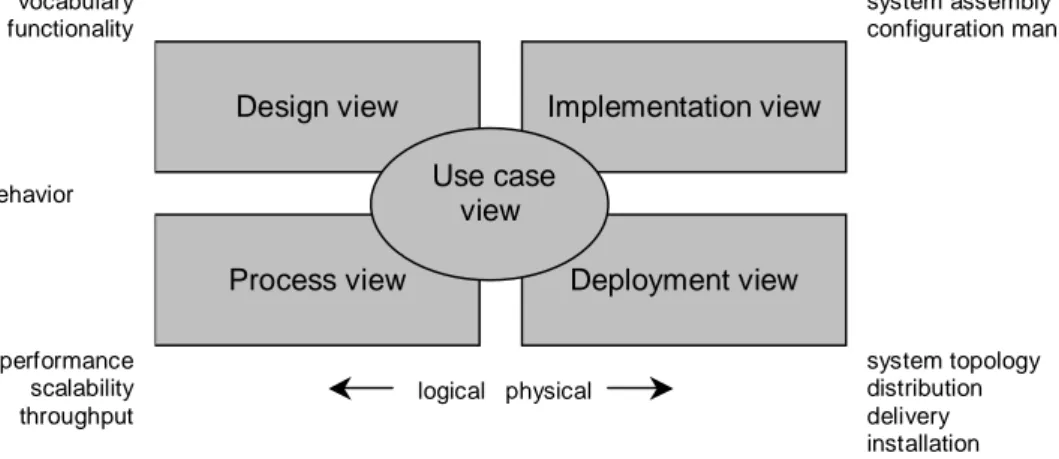
UML is a modeling language and not a method, meaning it is the graphical (mainly) notation that methods use to express designs (Fowler et al., 1997). In short UML is a language for visualizing, specifying, constructing, and documenting the artifacts of a software-intensive system (Booch et al., 1999). Different stakeholders (e.g. end-users, customers, analysts, designers, system integrators, testers, and project managers) look at a software system from different perspectives and therefore the architecture should be represented from different views. Booch et al. (1999) introduces five interlocking views that each are focused on a particular aspect of a system; see Figure 1.
system assembly configuration management system topology distribution delivery installation
Design view Implementation view
Process view Deployment view Use case view vocabulary functionality behavior performance scalability throughput logical physical
Figure 1: Modeling a system's Architecture (after Booch et al., 1999, p. 424)
By looking at one specific view alone, complexity decreases and different stakeholders can focus on aspects of a system that most concern them. Yet the different views interact with each other and thus together provide a complete description of a system's architecture.
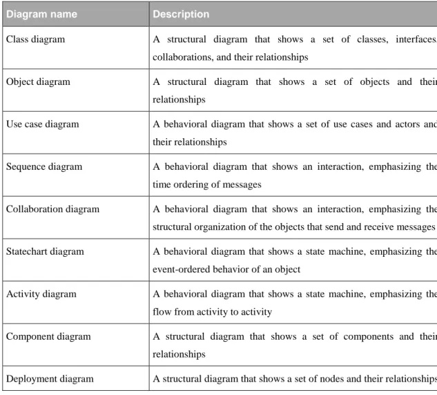
UML consists of nine different diagrams (Booch et al., 1999), which are described in Table 1.
Diagram name Description
Class diagram A structural diagram that shows a set of classes, interfaces, collaborations, and their relationships
Object diagram A structural diagram that shows a set of objects and their relationships
Use case diagram A behavioral diagram that shows a set of use cases and actors and their relationships
Sequence diagram A behavioral diagram that shows an interaction, emphasizing the time ordering of messages
Collaboration diagram A behavioral diagram that shows an interaction, emphasizing the structural organization of the objects that send and receive messages Statechart diagram A behavioral diagram that shows a state machine, emphasizing the
event-ordered behavior of an object
Activity diagram A behavioral diagram that shows a state machine, emphasizing the flow from activity to activity
Component diagram A structural diagram that shows a set of components and their relationships
Deployment diagram A structural diagram that shows a set of nodes and their relationships
Table 1: The nine diagrams included in UML (diagram descriptions taken from Booch et al. (1999, pp. 439-440))
In the use case view the behavior of a system as seen by different stakeholders is described. In this view the forces that shape a system's architecture are specified and not the exact organization of a software system (Booch et al., 1999). The static aspects of this view are captured in use case diagrams (see chapter 2.3). The dynamic aspects of this, as for all the other views, are captured in interaction diagrams (i.e. sequence diagrams and collaboration diagrams), statechart diagrams, and activity diagrams
(Booch et al., 1999).
The design view consists of the classes, interfaces, and collaborations that describe the vocabulary of a problem and its solution (Booch et al., 1999). In this view, the services a system should provide are described, i.e. the functional requirements. The static aspects of this view are captured in class diagrams and object diagrams.
The process view primarily addresses the performance, scalability, and throughput of a system and consists of the threads and processes that form a system's concurrency and synchronization (Booch et al., 1999). The same diagrams as for the design view are used but with a focus on active classes that represent the threads and processes of a system.
The implementation view describes the components and files that are used to assemble and release a system physically, i.e. the configuration management of a system release (Booch et al., 1999). The static aspects are captured in deployment diagrams.
Finally, the deployment view describes the nodes that form a system's hardware topology. The view addresses the distribution, delivery, and installation of the parts that make up a physical system (Booch et al., 1999).
The next subchapter provides brief descriptions of UML elements, which later are mentioned and discussed in the dissertation. Besides this the elements and diagrams of UML are not described further in this text (except for the notation of use cases and use case diagrams, see chapter 2.2 and chapter 2.3) since this dissertation is concentrated on the notation of use cases and use case diagrams. For a complete description of UML see Booch et al. (1999) and/or Rumbaugh et al. (1999).
2.1.1
Descriptions of UML elements mentioned in the dissertation
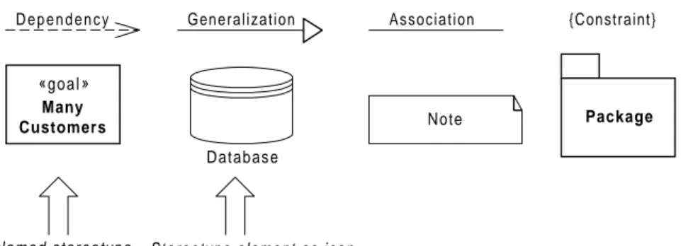
Figure 2 shows the notations for the basic UML elements that later are mentioned and discussed in the dissertation. Brief descriptions of these basic UML elements are given in the following subchapters in order to provide readers a better understanding of the contents of this dissertation.
Figure 2: The basic UML elements mentioned and discussed in this dissertation
In cases when a particular element and its relevant properties need to be described further, this is done in an appropriate section later in the dissertation. The descriptions given in the subchapters below are adopted from Booch et al. (1999).
2.1.1.1 Relationships
Relationships show connections among different things. UML consists of three major relationships which all are mentioned in this dissertation.
• Dependency
A dependency is a using relationship that is used to state that a change in one element (an independent thing) may effect another element that uses it (a dependent thing). {Constraint} Note Generalization Association «goal» Many Customers Database Package
N a m e d s t e r e o t y p e Stereotype element as icon
• Generalization
A generalization is a relationship between a general thing (a parent) and a specialized thing where the child (the specialized element) is substitutable for its parent. A child can override the behavior of an operation in the parent (i.e. polymorphism), and a child can also have own attributes and operations in addition to those found in the parent.
• Association
An association is a structural relationship specifying that objects of different things are connected to each other.
2.1.1.2 Extensibility mechanism s
UML contains three extensibility mechanisms that allow a user to extend the language in a controlled way. In this dissertation stereotypes and constraints are mentioned which both are described short below.
• Stereotypes
A stereotype makes it possible to create new kinds of building blocks similar to existing ones but specific to a particular problem. A stereotype is usually rendered as a name enclosed by guillemets but can also be depicted as an icon that is defined as a symbol for a particular stereotype item.
• Constraints
A constraint extends the semantic of a UML element and allows you to add new rules or modify existing ones. A constraint is rendered as a string enclosed by
brackets and specifies conditions that must be true if a model is to be well-formed.
2.1.1.3 Other mentioned elemen ts
Besides relationships and extensibility mechanisms two other basic elements of UML are mentioned in the dissertation. These are notes and packages, and they are described short below.
• Notes
A note is a symbol for depicting arbitrary comments or constraints attached to one or many elements.
• Packages
A package is a general-purpose mechanism for organizing modeling elements into larger chunks that can be manipulated as a group.
2.1.2
UML in systems deve lopment
As stated earlier, UML is only a modeling language and not a complete method. A method normally consists of both a modeling language and a process, where the latter describes recommended steps to undertake when developing a software system (Fowler et al., 1997). This implies that UML can be adopted and used in several methods or software development life cycles. However, Booch et al. (1999) states that the most benefit from the UML is given if the development process followed is:
• Use case driven
Meaning that use cases are used for establishing the desired behavior of a system, for verifying, validating and testing a system, and for facilitate communication between different stakeholders.
• Architecture-centric
Meaning that a system's architecture should be establish early in the development process and be used as an artifact for conceptualizing, constructing, managing, and evolving a system under development, i.e. the process of logically dividing the system into different subsystems and to establish simple and sensible dependencies between them.
• Iterative and incremental
Meaning that a system should evolve through iterations where each iteration add some new information or detail to the system. Each new iteration should focus on what will have the greatest impact on the system or the highest level of risk. By focus on the main functions, a usable system can be delivered earlier and by handle tough problems early the overall risk of a project is reduced. A set of iterations should produce an executable release and each new release should embodying incremental improvements (in function) over the other. Each ads new information.
The next chapter briefly describes some development processes, which uses UML as its modeling language. Furthermore an approach that shows how to use UML for business language is presented.
2.1.3
Use of UML
In this chapter three methods/processes and an approach for business modeling, which uses UML as modeling language, are briefly described.
2.1.3.1 The Rational Unified Pr ocess
The Rational Unified Process (RUP) is a software engineering process covering the entire software development lifecycle. The goal of RUP is to produce high-quality software that, within a predictable schedule and budget, meets the needs of its end users (Kruchten, 2000). In Jacobson et al. (1999) the developers of UML describes a theoretical framework for a development software process and RUP is a specific and detailed instance of this more generic process.
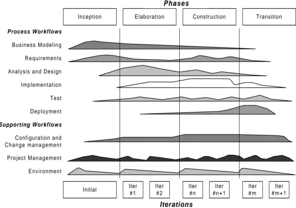
Figure 3: The software development life cycle used within RUP (after Kruchten, 2000, p.46)
Inception Elaboration Construction Transition Process Workflows
Business Modeling Requirements Analysis and Design Implementation Test Deployment Supporting Workflows Configuration and C h a n g e m a n a g e m e n t Project Management Environment Initial Iter #1 Iter #2 Iter #n Iter #n+1 Iter # m Iter # m + 1 Phases Iterations
RUP consists of nine core workflows and four phases. Each phase is concluded by a major milestone and the workflows are, through iterations, revisited again and again throughout the lifecycle (Kruchten, 2000) (see Figure 3 for an overview of RUP).
At each iteration, the workflows are repeated with various emphases and levels of intensity (Kruchten, 2000). The main goals of the phases are summarized below (Kruchten, 2000):
1. Inception Establish the objectives for the project
2. Elaboration Establish a project plan, a sound architectural foundation, and analyze the problem domain
3. Construction Develop, test, and integrate all components and application features into the product
4. Transition Move the software product to its end users
See Krutchen (2000) for a thorough description of RUP.
2.1.3.2 The SELECT Perspectiv e
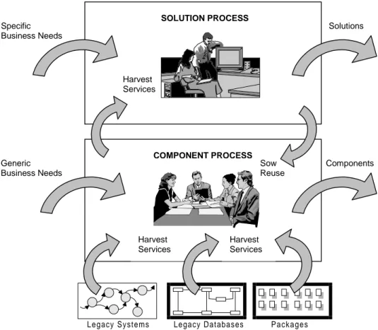
The SELECT Perspective is a component-based approach for developing enterprise systems which need to be delivered rapidly while facilitating reuse through component technology (Allen & Frost, 1998). The six core models within SELECT Perspective are based on UML, but other notations are used to develop business process models and logical data models.
development (RAAD) approach (Allen & Frost, 1998). The other key themes that underpin the SELECT Perspective process are iterations, product-focused development, incremental development, evolutionary development, constant validation, positive politics, and process refinement (Allen & Frost, 1998).
Figure 4: The SELECT Perspective process (after Allen & Frost, 1998, p.14)
The SELECT Perspective process consists of two sub-processes, which are named the solution process and the component process (Allen & Frosts, 1998). Figure 4 describe the relationship between the two sub-processes and below the aim of each process is presented.
Components Solutions Specific
Business Needs
Legacy Systems Legacy Databases Packages COMPONENT PROCESS SOLUTION PROCESS Harvest Services Harvest Services Harvest Services Sow Reuse Generic Business Needs
1. The solution process aimed at the development of solutions, typically in terms of user services, to provide early user value by maximize the reuse of existing services
2. The component process aimed at the development of components to provide commonly used business and/or data services to different departmental systems or to third parties
See Allen and Frost (1998) for a thorough description of the SELECT Perspective.
2.1.3.3 The ICONIX Unified Ob ject Modeling Approach
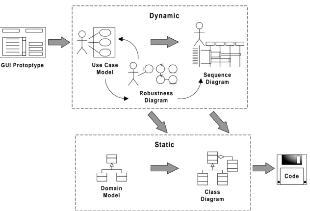
In Rosenberg and Scott (1999), Rosenberg argues that there is simply never enough time for modeling in the real world of software development. Therefore a streamlined approach to software development, that includes a minimal set of diagrams and techniques, is presented. The aim of ICONIX is to get from use cases to code quickly and efficiently (Rosenberg & Scott, 1999).
The three significant features of ICONIX are that the approach is iterative and incremental, offers a high degree of traceability, and offers a streamlined usage of the UML (Rosenberg & Scott, 1999). Figure 5 presents the essential elements of the ICONIX approach.
Figure 5: The ICONIX Unified Object Modeling Approach (after Rosenberg & Scott, 1999, p. 121)
The phases within ICONIX and their adherent milestones are presented below (Rosenberg & Scott, 1999):
Phase Milestone
1. Requirements analysis Requirements review
2. Analysis and preliminary design Preliminary design review
3. Design Detailed/critical design review
4. Implementation Delivery
See Rosenberg and Scott (1999) for a thorough description of the ICONIX approach.
Use Case Model Robustness Diagram Sequence Diagram Dynamic Static Class Diagram Domain Model GUI Protoptype Code
2.1.3.4 UML and business mode ling
Eriksson and Penker (2000) present an approach (not a method) that shows how UML can be used for business modeling. Eriksson and Penker (2000) argue that the use of the same modeling language for both business and software modeling ensures that documentation is consistent and facilitates communication between business modelers and software modelers. RUP for example, also uses UML for business modeling, but the approach presented by Eriksson and Penker (2000) is much more thorough and can help software developers to get a better understanding of a business before developing systems to support it.
All businesses have some sort of architecture and the business architecture is the basis for describing and understanding an enterprise by listing the required parts of a business, showing how the parts are structured and interact, and showing how the architecture should evolve (Eriksson & Penker, 2000). Eriksson and Penker (2000) suggest that four different views are used to show the different aspects of a business architecture:
• Business Vision Describes the overall vision of a business by describing a goal structure for the company and adherent problems that must be solved in order to reach the goals
• Business Process Describes the activities and value created in a business by illustrating the interaction between processes and resources in order to achieve the goal of each process, and the interaction between different processes
• Business Behavior Describes the behavior of each important resource and process in a business model
To be able to model a business's architecture with UML, Eriksson and Penker (2000) have used UML's extensibility mechanisms and created a set of extensions based on existing modeling elements of UML. The Eriksson-Penker Business Extensions provide symbols for modeling the processes, resources, rules and goals of a business system. When system needs for a business have been discovered through the business modeling, RUP or SELECT Perspective can be used develop the needed software systems.
See Eriksson and Penker (2000) for a thorough description of this business modeling approach.
2.2
Use Cases
The success of a software system and the satisfaction a software system yields depends in a great extend on how well the developers (and consequently the system) manage to fulfil the requirements, needs, and expectations of the end-users (Loucopoulos & Karakostas, 1995). A frequently discussed issue in system development has therefore been the communication problem between developers and end-users; they have a hard time understanding each other as they have different knowledge and frames of references. Use cases, however make it possible to express a problem in a way that can be understood by a wide range of stakeholders (Kruchten, 2000).
In short, a use case describes an interaction between a user and a software system, and represents a kind of task, which has to be done with the support from a system under
development (Stevens & Pooley, 2000). As the notation is seemingly straightforward, use cases facilitate communication between end-users, domain experts, and developers, which helps them to get a common understanding of a system. Use cases specifies what a system should do (i.e. desired behavior) but not how a behavior will be designed or implemented. Thus, with the help of use cases, stakeholders can communicate without getting hung up on details (Booch, et al., 1999). In UML, a use case is defined as follow:
A use case is a description of a set of sequences of actions, including variants, that a system performs to yield an observable result of value to an actor (Booch et al., 1999, p. 220).
In the UML Reference Manual (Rumbaugh et al, 1999) use cases are defined more exact and thorough, but the meaning is the same:
The specification of sequences of actions, including variant sequences and error sequences, that a system, subsystem, or a class can perform by interacting with outside actors (Rumbaugh et al., 1999, p. 488).
Besides providing different stakeholders with a common understanding of a system, use cases can be used to validate an architecture and to verify a system as it evolves during development (Booch et al., 1999). Hence, the use cases of a system describe the functional requirements of that particular system.
Three main characteristics of use cases are (Eriksson & Penker, 1998):
• A use case is always performed on behalf of an actor and thus is always initiated directly or indirectly by an actor.
• A use case must deliver a discernible value to an actor.
A use case is graphically represented as an ellipse, usually only including its name that distinguishes it from other use cases (see Figure 6).
Figure 6: A use case named Print Statusreport represented graphically
More than the use case name may be included in the ellipse. If a use case belongs to a package the use case name can be prefixed by the name of the package. In Figure 6 this could for example be Printings::Print Statusreport where Printings would be the name of the package in question. The ellipse may also contain attributes and operations, which can be seen as objects inside the use case, which are needed to describe its outside behavior. However, apart from the name, extension points are the most usual inclusion in the ellipse. Extension points are described in chapter 2.2.2.3.
2.2.1
Actors
An actor is someone or something that interacts with a system. When talking about use cases, an actor represents a coherent set of roles that users of the use cases play (Booch et al., 1999). An actor is found outside the system in question and represents a role a human or another system plays with the system. It is important to realize the difference between an actor and a user i.e. an actor does not represents a particular individual, an actor represents a role that someone might play (Stevens & Pooley, 2000). A concrete user can interact with a system as more than one type of actor and more than one concrete user can act as a particular actor. For example a purchaser may also perform
Print S tatusreport
some assortment work and it may exist several purchasers.
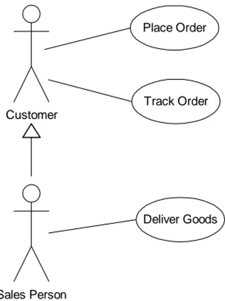
The ordinary way to graphically represent an actor is with a stick man figure (see Figure 7). By using UML's extensibility mechanisms an actor can also be stereotyped to be shown in some other way, depending on the purpose (Booch, et al., 1999). For example, if a printer interacts with a system, a stick man figure may not be the best way to represent this actor.
Actors may have similarities in the way the interact with a system, i.e. they can communicate with the same set of use cases in the same way (Rumbaugh et al., 1999). When similarities exists between different actors, this can be expressed through a generalization relationship between them as shown in Figure 7. Descendant actors inherit all the roles and all relationships to use cases an ancestor actor holds.
Customer
Place Order
Track Order
Sales Person
Deliver Goods
Figure 7: Generalization between actors and their connection to a system through use cases
The only way to connect actors to use cases is through communication association lines. An association between an actor and a use case specifies that they can communicate
with each other and that both are able to sending and receiving messages to the other one (Booch et al., 1999).
2.2.2
Relationships betwee n use cases
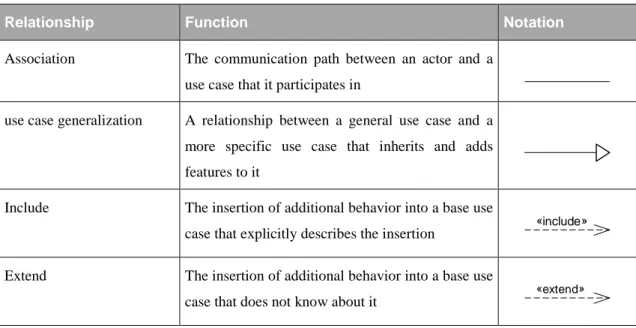
Table 2 presents the different relationships a use case can participate in.
Relationship Function Notation
Association The communication path between an actor and a use case that it participates in
use case generalization A relationship between a general use case and a more specific use case that inherits and adds features to it
Include The insertion of additional behavior into a base use
case that explicitly describes the insertion «include»
Extend The insertion of additional behavior into a base use
case that does not know about it «extend»
Table 2: Kinds of use case relationships (after Rumbaugh et al., 1999, p. 65)
The association relationship between use cases and actors is described in chapter 2.2.1 whereas the other three relationships, which are used to organize relationships between different use cases, are described in detail in the following subchapters. Generalization, include, and extend relationships between use cases are applied to factoring out common behavior and variants (Booch et al., 1999).
2.2.2.1 Use case generalization
A generalization relationship between use cases implies that the child use case inherits all elements (attributes, operations, and behavior sequences) of the parent use case. A child use case can also add own elements and override/modify elements inherited from its parent. There can also exist include or extend relationships to the child, which also modify the behavior inherited from the parent (Rumbaugh, 1999).
To indicate that use case A is a specialization of use case B, a generalization relationship is drawn from A to B (OMG, 2000a). One use case can have several parents and a use case can also be a parent to several other use cases (OMG, 2000a).
2.2.2.2 Include relationships
An include relationship means that the behavior of a supplier use case is included at one location in the base use case sequence of behavior. When the base use case reaches an inclusion point specified in the sequence of behavior, the supplier use case is executed until it is complete. Then the base use case resumes its sequence of behavior beyond the inclusion point (Rumbaugh et al., 1999). To indicate that use case A also contain the behavior of use case B, an include relationship is drawn from A to B (OMG, 2000a).
Include relationships are used to avoid describing the same flow of events several times (Booch et al., 1999) and by putting a common behavior in a use case of its own, this use case can be included in several other use cases. An included use case never stands alone and can only be instantiated as part of a base use case (Booch et al., 1999). However, an included use case may not be dependent on a base use case since other use cases also should be able to include its behavior (OMG, 2000a). Moreover, OMG (2000a) declares
that a base use case only may be dependent of the result from an included use case and not on its structure.
2.2.2.3 Extend relationships
An extend relationship means that a base use case can be extended by behavior sequence segments from another use case (Rumbaugh et al., 1999). A base use case may not be dependent on an extension use case (OMG, 2000a) and a base use case can only be extended at certain locations, called extension points.
An extension use case can contain one or more different behavior sequence segments and the base use case contains a list of extension point names, one for every sequence segment in the extension use case (Rumbaugh et al., 1999). An extension point represents one or several locations in a base use case, where additional behavior may be inserted.
An extend relationship (may) contain a condition, which may use attributes from the base use case. When a base use case reaches an extension point, the condition is evaluated and if true, the corresponding behavior segment from the extension use case is executed (Rumbaugh et al., 1999). If a base use case contains several extension points, the condition is evaluated at the first extension point and if true, the different parts of the extension use case are inserted into the base use case at the locations of each extension point (OMG, 2000a).
Extend relationships are used to separate optional behavior from mandatory behavior or to model a subflow that only is performed under a given condition (Booch et al., 1999).
To indicate that use case A may extend use case B, an extend relationship is drawn from A to B (OMG, 2000a). One use case may extend several other use cases and a use case may also be extended by several extension use cases (OMG, 2000a).
2.2.3
Use case specification s
The behavior of a use case is obviously not visible in its graphical form and therefore the flow of events of a use case is usually described in text, i.e. a use case specification. There are advantages with using narrative text descriptions since users and customers are familiar with the notation and do not need any training to understand it, but at the same time text descriptions are often ambiguous and lack structure (Achour et al., 1999). The disadvantages are however taken care of when the use cases are further refined (see chapter 2.2.4). According to Booch et al. (1999) the use case specification should include how and when the use case in question starts and ends, when the use case interacts with the actors and what objects are exchanged, and the basic flow of events and the alternative flows of the behavior. In addition to this, Eriksson and Penker (1998) argue that also the objective for the use case should be apparent, i.e. what it is trying to achieve.
The flow of events of a use case can be specified in several ways, for example with informal structured text, formal structured text (with pre- and postconditions), and pseudocode (Booch et al., 1999). In the context of an ATM system, the use case ValidateUser might be specified in the following way:
Main flow of events: The use case starts when the system prompts the Customer for a PIN number. The Customer can now enter a PIN number via the keypad. The Customer commits the entry by pressing the Enter button. The system then Checks this PIN number to see if it is valid. If the PIN number is valid, the system acknowledges the entry, thus ending the use case.
Exceptional flow of events: The Customer can cancel a transaction at any time by pressing the Cancel button, thus restarting the use case. No changes are made to the Customer's account.
Exceptional flow of events: The Customer can clear a PIN number anytime before committing it and reenter a new PIN number.
Exceptional flow of events: If the Customer enters an invalid PIN number, the use case restarts. If this happens three times in a row, the system cancels the entire transaction, preventing the Customer from interacting with the ATM for 60 seconds (Booch et al., 1999, p. 224).
If a base use case has include relationships and/or extend relationships, the location where another use case is included or the extensions points belonging to an extend use case are specified in the flow of events. An advantage of organizing use cases in an appropriate way is that you do not have to specify the same flow of events several times and thus the specifications become shorter. For example, the main flow of events for a base use case called Place Order which includes a use case named Validate user and which can be extended by a use case named Place Rush Order (with an extension point called set priority) could specified in the following way:
Main flow of events: include (Validate user). Collect the user's order items. (set priority). Sumbit the order for processing (Booch et al., 1999, p.228).
As mentioned above, the use case specification can be written in several ways. For example Rosenberg and Scott (1999) uses the terms base course of action and alternative courses of action instead of main flow of events and exceptional flow of events, and Achour et al., (1999) talks about main success scenario and variations. Cockburn (2001) prefer to use one column of text with numbered steps and a numbering
convention in the extensions section that involves combinations of digits and letters (e.g. 2a, 2a1, 2a2, and so on). The numbering provides a clear connection between a step in the main success scenario and adherent extensions. However, the important thing is to use the same terminology and format for all the use cases in a project order to alleviate the disadvantages with natural language (Regnell et al., 1995).
There exists lot of research and opinions about how to write use case specifications and this in not the area of this dissertation. This dissertation is concern with problems with the graphical notation of use cases, i.e. use case diagrams.
2.2.4
Scenarios
A use case represents several sequences of actions while a scenario is one specific sequence of actions that illustrates behavior (Booch et al., 1999). A more thorough definition of scenarios is given by Plihon et al. (1998):
At a functional level, a scenario is a description denoting similar parts of possible behaviours limited to a subset of purposeful state components, actions and communications taking place among two or several agents (Plihon et al., 1998, p. 14).
The definition above can be somewhat hard to grasp and the word scenario is used inconsistently and it is sometimes used as a synonym for use case (Fowler & Scott, 1997). Booch et al. (1999) however gives a much more understandable description of the real meaning with scenarios in the context of UML:
Scenarios are to use cases as instances are to classes, meaning that a scenario is basically one instance of a use case (Booch et al., 1999, p. 225).
A scenario describes one concrete sequence of interactions between an actor and a system. Scenarios are therefore particularly useful for the elicitation of requirements and
often serves as blueprints for a use cases (Dutoit & Paech, 2000). According to Booch et al., (1999), the more general use cases are however developed before the different scenarios are evolved in detail. A scenarios can also be used as a test case for its use case (Dutoit & Paech, 2000).
When the understanding for a system under development increases, each scenario usually is specified graphically in a sequence diagrams (Booch et al., 1999). In practice scenarios are usually written as textual narratives or, more formally, described in sequence diagrams (Jarke, 1999). Ericsson and Penker (1998) however suggest that activity diagrams are used instead of sequence diagrams. According to a study of scenario usage in practice scenarios are most often described in a textual form (Wiedenhaupt et al., 1998). 80% of 15 investigated European scenario based projects used this form of description.
2.3
Use case diagrams
The graphical notation of use cases and actors enables stakeholders to view relations between different use cases (and actors) apart from their realization (Booch et al., 1999). This is exactly what a use case diagram shows; the relationships among use cases and actors within a system.
Use case diagrams are used to model the use case view of a system, which in most cases means modeling the context of a system or some of its elements, or to model the requirements of the behavior of elements of a system (Booch et al., 1999). Use case diagrams presents an outside view of how elements in a system may be used in context and the visualization of the behavior of a system helps users to get an understanding of
how to use it and helps developers to implement it (Booch et al., 1999).
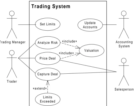
Commonly a use case diagram contains use cases, actors and the relationships between them (see Figure 8 for an example).
Figure 8: An example of a use case diagram for a financial trading system (after Fowler & Scott, 1997, p. 45)
The system boundary is represented with a rectangle where the use cases are found inside the boundary and the actors are found outside it. Somewhere inside the rectangle the name of the system or the use case diagram is also found. In this way a use case diagram presents a system as a black box; it shows what is outside the system and how actors outside the system can interact with it, but it does not show how that system works on the inside. You could say that the use cases represent the interface to a system.
Analyze Risk Price Deal Capture Deal « extend» Valuation Limits Exceeded «include» «include» S a l e s p e r s o n T r a d i n g M a n a g e r Set Limits Trading System Trader Update Accounts Accounting S y s t e m
3
Problems with th e graphical use case notation
This chapter presents problems with the graphical use case notation reported by different researchers. Only little literature about expressiveness and ambiguity problems within the static view of use cases has been found, i.e. problems with the use case diagrams. Most literature found is concern about how to write use case specifications and the process of developing use cases.
Possible reasons for the lack of research may be that UML version 1.3 is rather new, as it was released in march 2000 (OMG, 2000a), or that many researchers share Cockburn’s (2001) view who deem use case diagrams only as a table of contents to the use cases. Cockburn (2001) considers use case diagrams as context diagrams for a system, showing the "big picture" and thinks that the description of the use cases behavior is more important (the use case specifications). In an implementation view it is of course easy to claim and justify that the use case specification is more important than the use case diagrams. However, use case diagrams can be helpful when developers wants to communicate with end-users and customers easily and fast. They make elements understandable and approachable by presenting an outside view of how elements may be used in a context (Booch et al., 1999). The relationships used in the use case specifications are the same as the ones used in the use case diagram. Hence, to be able to get a comprehensive understanding without having to read a lot of documents, it could be desirable to have the ability to express as much things and aspects in the diagrams as in the specifications.
Developers must not forget that the most important property of a software system is that it fulfills the end-users and customer’s expectations. Therefore, this work can fill a gap
in this research area. By eliminate expressiveness and ambiguity problems within the use case notation, it will be easier for different stakeholders to get a common view and understanding of a system that is to be created.
The problems found in the literature are divided into ambiguity problems (chapter 3.1) and expressiveness problems (chapter 3.2). The last of the expressiveness problems (chapter 3.2.4) is however not reported by researchers but can be derived from reasoning about how use case diagrams are used practically.
3.1
Ambiguities in the graphical use case notation
Four ambiguity problems with the graphical use case notation were found in the literature and they are reported in the following subchapters.
3.1.1
The semantics of «inc lude» is unclear
Simons and Graham (1999) notice that the semantics of the include relationship is unclear. It is not clear if included use cases are atomic subroutines that are executed as a whole or if included use cases also can be interleaved routines, where the latter means that a base use case uses elements of an abstract use case by inserting them into its own sequence.
The «uses» relationship was in UML 1.1 defined as interleaved routines but developers commonly considered them as subroutine calls (Simons & Graham, 1999). The «uses» relationship was in UML 1.3 replaced by the «include» relationship and although that all examples given by Booch et al. (1999) describe subroutines, and not interleaved
routines, the authors do not make the semantic absolutely clear. Simons and Graham (1999) would therefore like to see a clear statement that included use cases are atomic subroutines that are executed as a whole.
3.1.2
The semantics of «ex tend» cannot handle exceptions
The extend relationship is, as described earlier used to represent optional behavior, which is executed if a condition is satisfied. However, developers also commonly use the extend relationship to model exceptions, but the semantic of «extend» does not support this (Simons 1999; Simons & Graham, 1999).
The semantics of «extend», given by Booch et al. (1999), state that after an «extend» use case is carried out, the control then returns to the exact point in the base use case it was raised from. However, when an exception is carried out, the control never returns to the point in the base use case it was raised from, but it may return to the end of the failed transaction, or not at all (Simons, 1999; Simons & Graham, 1999) (cf. Figure 9).
Place Order
Rush Order
Withdrawal
Abort
«extend» as insertion «extend» as exception
KEY: flow sequence element conditional guard Figure 9: Control flows for insertions and exceptions (after Simons, 1999, p. 7)
In addition to the reported problem (Simons, 1999; Simons & Graham, 1999), it can of course be hard to determine if an «extend» use case describe an insertion, exception, or an alternative. The latter use of the extend relationship is described in the next chapter.
3.1.3
The semantics of «ex tend» cannot handle alternatives
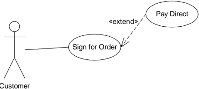
Besides expressing insertions and exceptions, developers commonly use «extend» to model alternatives (Simons, 1999; Simons & Graham, 1999). Figure 10 shows an example of this where the use case Pay Direct is an alternative to Sign for Order.
Customer
Sign for Order
Pay Direct «extend»
Figure 10: An example of where the extend relationship is used to model an alternative
Figure 11 shows how the control of flow should transfer out to a parallel flow if an extend relationship is used to model an alternative. Due to the semantics of «extend», the use case Sign for Order would still be executed after the inserted optional behavior (the alternative Pay Direct) had been carried out. A construction like the one in Figure 10 is therefore nonsensical (Simons, 1999; Simons & Graham, 1999).
Sign for Order
Pay Cash
«extend» as alternative
KEY: flow sequence element conditional guard Figure 11: Control flow for alternatives (after Simons, 1999, p. 7)
As stated earlier it can be hard to determine the meaning of an «extend» use case. Use case diagrams are dangerously ambiguous and to establish the meaning of extend relationships, developers have to rely on intuitions about the use case names (Simons, 1999; Simons & Graham, 1999).
3.1.4
Generalization betwe en actors can cause redundancy
Figure 12 shows an example where generalization between actors is used. However, in some cases generalization between actors will introduce redundancy to a use case diagram (Cox & Phalp, 2000).
According to the use case diagram in Figure 12, a Mangager can Send Requests (Borrow Equipment Request and New Equipment Request) to a Manager, but a Manager would probably not do this. A Manager would more likely make a request and give permission to that request in one single motion and besides that
only receive requests. Member Borrow Equipment Request New Equipment Request Pay Fee Send Instant Message Manager Reply to Request
Figure 12: An example of possible redundancy from generalization between actors
Cox and Phalp (2000) suggest two possible solutions to this problem. Either a separate use case solely for Manager (like Make and Grant Own Request) could be included or the generalization relationships between the actors could be dropped. The latter solution would however add clutter to the use case diagram as all necessary communication association lines from Manager to all the required use cases would have to be drawn (Cox & Phalp, 2000). Neither the first solution would completely solve the problem, since a Manager theoretical still would be able to send requests to himself/herself. The remark about the first solution is however not mentioned by Cox and Phalp (2000).
3.2
Limited expressive ness in the graphical use case notation
The following subchapters report expressiveness problems with the graphical use case notation. Three problems with the notation, that can be seen as expressiveness problems were found in the literature. Another expressiveness problem, not reported by researchers, is also included. The latter expressiveness problem can however easily be derived from reasoning about how use case diagrams are used practically.3.2.1
Long-range logical d ependencies cannot be expressed
According to Simons (1999) and Simons & Graham (1999), use case diagrams promotes a highly localized perspective where important long-range dependencies between use cases are missed.
Buying system
Customer
Sign for Order
Pay Direct «extend»
Supplier
Pay Invoice Send Invoice
Claim Refund
Deliver Goods
Return Goods «extend»
«extend»
Figure 13: A use case diagram where logical dependencies between use cases exist
Sign for Order is carried out earlier (Sign for Order and Pay Direct are alternatives and, for now, we ignore the problem described in chapter 3.1.3). In the same way, Pay Direct and Claim Refund are secretly interdependent. If a customer choose to pay direct for some goods, he or she must get a refund if returning faulty goods, whereas when using an invoice he or she can simply reduce the amount.
Wegmann and Genilloud (2000) also observe that use case diagrams does not provide a way to specify in which order related use cases should be carried out. Cox and Phalp (2000) present a similar discussion and declare that one might decide that use cases that logically are dependent are totally unrelated when reviewing a use case diagram.
Wegmann and Genilloud (2000) suggest that related use cases are numbered (e.g. 1 is followed by 1.1 which is followed by 1.1.1). It is then possible to illustrate the sequence in which use cases will be executed, they argue.
3.2.2
System response to p assive actors cannot be expressed
The communication association lines used between actors and use cases are normally undirected. Due to this it is impossible to model situations where a passive actor receive some information from a use case (Cox & Phalp, 2000).
Figure 14 shows an example where a one way system response would be desirable to express. The actor Loan Handling Officer instantiates Perform Credit Report and Bank Customer should then receive a response from this use case. If a communication association line from Bank Customer to the use case Perform Credit Report was drawn this could be shown. However, this would also imply
that the actor Bank Customer also would be able to instatiate the use case Perform Credit Report, which they should not.
Bank Customer
Make Loan Request
Loan Handling Officer Perform Credit
Report
Figure 14: An example where a response to a passive actor would be desirable to express
Cox and Phalp (2000) claim that arrowheads were used on the association lines in use case diagrams in UML 1.1 (Rational, 1997) but support for this claim could not be found in Rational (1997). If that was allowed or not is however not important since it is not used on the lines in use case diagrams in UML 1.3 (OMG, 2000a). Cox and Phalp (2000) think that the use of directed arrows for use case diagrams might be considered for future versions of UML. If directed arrows were allowed, situations where passive actors only receive information from a use case could be expressed, they argue.
3.2.3
Included use cases ca nnot be directly instantiated by actors
Cox and Phalp (2000) state that it should be possible for actors to instantiate included use cases directly. However, Booch et al. (1999) state that an included use case cannot be instantiated directly by an actor.
Figure 15 shows an example where it would be desirable to let actors directly instantiate the included use case Access Products. A Customer as well as a Supplier
would of course prefer to be able to access the list of products without having to place an order or having to update any products.
Customer Supplier Place Order Access Products Update Products «include» «include»
Figure 15: An example where associations between actors and an included use case would be desirable
3.2.4
Information about pr esent expansions cannot be shown
Use case diagrams can contain many relationships, which add clutter into the diagrams. If complicated include and extend relationships exist in a diagram, Booch et al. (1999) suggest that these elements are lifted out to another diagram.
Figure 16 shows an example on how a complex part of a use case diagram could be simplified by only showing the base use cases. A problem with this is however that it is not possible, only by looking at the simplified use case diagram (the lower use case diagram in Figure 16), to detect that the use cases are expanded in another diagram.
1999). With the help of packages, groups of related elements can be expanded or collapsed into an icon and allowing developers to view one package at a time (Eriksson & Penker, 1998). Thus, whole use case diagrams can easily be collapsed into a package, but how do you show that a part of a use case diagram can be expanded? Booch et al., (1999) mention that packages are allowed inside use case diagrams to group elements into larger chunks but no detailed description concerning how to do this is given.
Customer Track Order Place Order «extend» Customer «include» «include» Validate Transaction
Place Rush Order
Track Order Validate User Check Password Retinal Scan Place Order «include»
Figure 16: An example of how a use case diagram can be simplified to only show main functionalities
With the use of packages, as shown in Figure 17, the problem could be solved, but only partly. Every element included in a package is uniquely owned by exactly one package
(Booch et al., 1999), but the «include» use case Validate User is part of both Place Order and Track Order and how should this be handled? Hence, if you only want to show a simplified view of a use case diagram, normal packages cannot be used in the comprehensive use case diagram if several base use cases possess relationships to the same use case when described in detailed.
Customer
Place Order
Track Order
3.3
A summary of the problems
Table 3 presents a summary of the problems described in chapter 3.1 and chapter 3.2.
1 Ambiguity problems
Problem Short description
1.1 The semantics of «include» is unclear
Booch et al. (1999) do not make it absolutely clear if included use cases are atomic subroutines
1.2 The semantics of «extend» cannot handle exceptions
Due to its semantics, «extend» can actually not be used to describe exceptions and if its done it can be hard to determine this meaning when viewing a use case diagram
1.3 The semantics of «extend» cannot handle alternatives
Due to its semantics, «extend» can actually not be used to describe alternatives and if its done it can be hard to determine this meaning when viewing a use case diagram
1.4 Generalization between actors can cause
redundancy
Through the use of generalization between actors, a specialized actor may be able to initiate use cases which are intended to be used only by a more general actor
2 Expressiveness problems
Problem Short description
2.1 Long-range logical dependencies cannot be expressed
Dependencies between logically dependent use cases and the order in which related use cases should be carried out cannot be specified in a use case diagram
2.2 System response to passive actors cannot be expressed
Due to the undirected association line, responses from a use case to a passive actor cannot be expressed in a use case diagram, as it would indicate that use case also could be instantiated by the actor
2.3 Included use cases cannot be directly instantiated by actors
Cox and Phalp (2000) argue that it should be possible for actors to instantiate included use cases directly, but this cannot be done according to Booch et al. (1999)
2.4 Information about present expansions cannot be shown
In situations when ordinary packages cannot be used it is not possible to detect if a use case in a use case diagram is expanded in another diagram
4
Use case diagram s in practice
An interview study was carried out to acquire knowledge about what users of use cases and use case diagrams think about the problems found in the literature and also to acquire knowledge about how the practitioners in practice deal with the difficulties they recognize. Moreover, the interviews were used to investigate if practitioners recognize any other problems with the use case notation, not found in the literature study.
The number of interviews conducted are six, and all the respondents have in some way come across use cases in their profession. All interviews were performed by a private talk with each respondent and each interview took about one hour to carry out. During each interview notes were taken. Within a couple of hours, after each interview, a more complete transcription of the interview was developed from the notes.
The questions were in most of the cases of an open nature without any predefined answer alternatives. The respondents were firstly asked if they recognized any ambiguity or expressiveness problems with the use case notation. Then each problem described in chapter 3 was explained and the respondents were asked if they shared the researcher/researchers opinion and/or if they had come across the problem themselves. For each problem the respondents were also asked how they deal with the problem in practice or if they had any idea on how it could be moderated. Lastly the respondents were asked again if they, after the identified problems with the notation had been presented to them, recognized any ambiguity or expressiveness problems with the use case notation. When needed, appropriate follow-up questions were asked.