2019:07
General data in accordance with the
requirements in Article 37 of the
Euratom Treaty
Abstract
The purpose of this report is to provide the European Commission with general data relating to plans for the decommissioning of the Barsebäck nuclear power plant, Barsebäck 1 and Barsebäck 2, that will enable the Commission to determine whether the implementation of the plans is liable to result in the radioactive contamination of the water, soil or airspace of another European Union Member state. The structure of the document follows the recommendations given in 2010/635/Euratom on the application of Article 37 of the Euratom Treaty.
Barsebäck 1 commenced operation in 1975 followed by Barsebäck 2 two years later. Both reactors were of the type boiling water reactors with a net electrical output 615 MW each. Barsebäck 1 and Barsebäck 2 were shut down permanently in 1999 and 2005 respectively, due to political decisions.
In 2006 the remaining nuclear fuel was transported off-site; since then Barsebäck nuclear power plant has been in Care and Maintenance operation and will continue to be so until 2020 according to current planning when dismantling and demolition is anticipated to start. This report presents an assessment of the maximum expected emissions of radioactivity to air and water during decommissioning.
The assessment also includes a dose evaluation to a reference popula-tion living close to the power plant.
The dose to the reference group from radioactivity released during normal conditions at the plant is less than 0,003 µSv/year. As the dose to the reference group is less than 10 µSv/year, and there are no excep-tional exposure pathways, no dose assessment is required for other EU member states.
The dose to the reference group from radioactivity released during a hypothetical radiological accident at the plant is less than 0,1 mSv. As the dose to the reference group is less than 1 mSv, and there are no exceptional exposure pathways, no dose assessment is required for other EU member states
2019:07
General data in accordance with the
requirements in Article 37 of the
Euratom Treaty
This report has been completed by the Swedish Radiation Safety Authority, SSM, mainly based on information provided by the license holder, Barsebäck Kraft AB, BKAB. SSM has controlled that the general data provides the necessary informa-tion and that it follows the guideline of the most recent recommendainforma-tions of the application of Article 37 of the Euratom Treaty.
Content
0. Introduction ... 4
0.1. Barsebäck Nuclear Power Plant ... 4
0.2. Decommissioning licensing procedures ... 5
0.3. Decommissioning plan ... 6
1. The site and its surroundings ... 9
1.1. Geographical, topographical and geological features of the site and region ... 9
1.2. Seismology ... 11
1.3. Hydrology ... 12
1.4. Meteorology ... 14
1.5. Natural resources and foodstuffs ... 15
1.6. Other activities in the vicinity of the site ... 16
2. The installation ... 18
2.1. Brief description and history of the installation to be dismantled ... 18
2.2. Ventilation systems and the treatment of gaseous and airborne wastes ... 22
2.3. Liquid waste treatment ... 24
2.4. Solid waste treatment ... 27
2.4.1. Treatment at site ... 27
2.4.2. Treatment off site ... 28
2.4.3. Package ... 28
2.4.4. Storage on site ... 29
2.5. Containment ... 30
2.6. Interim storage 2 ... 31
2.6.1. Main features of the installation ... 31
2.6.2. Ventilation systems and the treatment of gaseous and airborne waste ... 32
2.6.3. Liquid waste treatment ... 32
2.6.4. Solid waste treatment ... 32
2.6.5. Containment ... 32
2.6.6. Decommissioning and dismantling ... 32
3. Release from the installation of airborne radioactive effluents under normal conditions ... 34
3.1. Authorisation procedure in force ... 34
3.1.1. Legislation on nuclear activities ... 34
3.1.2. Discharge limits and associated requirements for decommissioning ... 35
3.1.3. Environmental impact assessment ... 36
3.2. Technical aspects ... 37
3.2.1. Origins of the radioactive effluents, their composition and physicochemical forms ... 37
3.2.2. Annual discharges expected during dismantling and demolition ... 42
3.2.3. Management of the effluents, methods and paths of release ... 44
3.3. Monitoring of discharges ... 45
3.3.1. Sampling, measurement and analysis of discharges ... 45
3.3.2. Principal features of the monitoring equipment ... 46
3.3.3. Alarm levels and intervention actions ... 48
3.4. Evaluation of transfer to man ... 48
3.4.1. Models, including where appropriate generic models, and parameter values used to calculate the consequences of the releases in the vicinity of the plant ... 49
3.4.2. Evaluation of the concentration and exposure levels associated with the
envisaged discharge limits for the dismantling operations cited in 3.1 above: ... 57
3.5. Interim storage 2 ... 59
3.5.1. Authorisation procedure in force ... 59
3.5.2. Technical aspects ... 59
3.5.3. Monitoring of discharges ... 61
3.5.4. Evaluation of transfer to man ... 61
3.5.5. Radioactive discharges to atmosphere from other installations ... 61
4. Release from the installation of liquid radioactive effluents in normal conditions ... 62
4.1. Authorisation procedure in force ... 62
4.2. Technical aspects ... 63
4.2.1. Origins of the radioactive effluents, their composition and physicochemical forms ... 63
4.2.2. Annual discharges expected during dismantling ... 63
4.2.3. Management of the effluents, methods and paths of release ... 65
4.3. Monitoring of discharges ... 65
4.4. Evaluation of transfer to man ... 65
4.4.1. Models, including where appropriate generic models, and parameter values used to calculate the consequences of the releases in the vicinity of the plant ... 65
4.4.2. Evaluation of the concentration and exposure levels associated with the envisaged discharge limits for the dismantling operations cited in 4.1 above .... 66
4.5. Interim storage 2 ... 67
4.5.1. Authorisation procedure in force ... 67
4.5.2. Technical aspects ... 67
4.5.3. Monitoring of discharges ... 67
4.5.4. Evaluation of transfer to man ... 68
4.5.5. Radioactive discharges to water from other installations ... 68
5. Disposal of solid radioactive waste from the installation ... 69
5.1. Solid radioactive waste ... 69
5.1.1. Categories of solid radioactive wastes and estimated amounts ... 70
5.1.2. Processing and packaging ... 72
5.1.3. Storage arrangements on site ... 74
5.2. Radiological risks to the environment ... 74
5.3. Off-site arrangements for the transfer of waste ... 75
5.4. Release of material from the requirements of the basic safety standards... 76
5.5. Interim storage 2 ... 79
5.5.1. Solid radioactive waste ... 79
5.5.2. Radiation risks to the environment ... 79
5.5.3. Off-site arrangements for the transfer of waste... 79
5.5.4. Release of materials from the requirements of the basic safety standards ... 79
6. Unplanned discharge of radioactive effluents ... 80
6.1. Review of accidents of internal and external origin which could result in unplanned releases of radioactive substances ... 80
6.1.1. External events ... 81
6.1.2. Internal events ... 81
6.1.3. Risks during interim storage ... 82
6.2. Reference accident(s) taken into consideration by the competent national authorities for evaluating possible radiological consequences in the case of unplanned releases ... 82
6.3.2. Accidents entailing releases into an aquatic environment ... 86
6.3.3. Results from the dose calculations ... 86
6.3.4. Interim storage 2 ... 88
7. Emergency plans, agreements with other member states ... 89
8. Environmental monitoring ... 90
8.1. General Description ... 90
8.2. The environmental radiological monitoring at the Barsebäck NPP ... 90
8.3. Measurement of external dose rate... 94
9. References ... 97
Appendices ... 99
Appendix 1 - Definitions and abbreviations used in this report ... 99
Appendix 2 - The system for dealing with Swedish radioactive waste ... 101
Appendix 3 - Maximum expected doses to reference group from emissions to air from B1 (113 m) ... 103
Appendix 4 - Maximum expected doses to reference group from emissions to air from B2 (113 m) ... 104
Appendix 5 - Maximum expected doses to reference group from emissions to air from B1 + B2 (20 m) ... 105
Appendix 6 - Maximum expected doses to reference group from emissions to air from B1 + B2 ... 106
Appendix 7 - Maximum expected doses to reference group from emissions to water from B1+B2 ... 107
Appendix 8 - Maximum expected doses to reference group from emissions to water and air from B1 + B2 ... 108
0. Introduction
The purpose of this report is to provide the European Commission with general data relat-ing to the plans for decommissionrelat-ing the Barsebäck nuclear power plant, comprisrelat-ing Barsebäck 1 (B1) and Barsebäck 2 (B2), that will enable the Commission to determine whether the implementation of the plans is liable to result in the radioactive contamination of water, soil or airspace of another European Union Member state. The decommissioning plan includes the construction of a new interim storage facility (interim storage 2) in order to provide required interim storage capacity.
This report follows the guidelines in Annex III (decommissioning of existing plant) and Annex II (construction of interim storage 2) of the recommendation of the application of Article 37 of the Euratom Treaty (2010/635/Euratom) [1]. At the beginning of each chapter in this report, the link to each Annex will be described. The report has been completed by the Swedish Radiation Safety Authority (SSM) mainly based on information provided by the license holder, Barsebäck Kraft AB (BKAB). SSM has controlled that the general data provides the necessary information and that it follows the mentioned guidelines [1]. According to the Swedish Nuclear Activities Act (1984:3), it is the obligation of BKAB, as holder of the nuclear licence, to decommission and dismantle the Barsebäck nuclear power plant (Barsebäck NPP).
The final goal for the decommissioning of the Barsebäck NPP is that the site shall be re-leased from the regulatory control of the Nuclear Activities Act.
The most common definitions and abbreviations used in this report are listed in appendix 1.
0.1. Barsebäck Nuclear Power Plant
The Barsebäck NPP is owned by Sydkraft Nuclear Power (SNP) and operated by BKAB which also holds the nuclear licence to operate and decommission the plant. SNP is a part of the Uniper Group, an international energy company active in the energy market extend-ing from North America to Asia, with Europe and Russia beextend-ing the core markets. The head office (Uniper) is located in Düsseldorf, Germany.
The Barsebäck NPP is situated in the southern part of Sweden on the west coast, 20 km north of the city of Malmö. The nearest European Union member state is Denmark, with its capital Copenhagen 20 km west of Barsebäck NPP.
B1 commenced operation in 1975 followed by B2 two years later. Both reactors were of the type boiling water reactors (BWR) with a net output (electrical) 615 MW each. B1 and B2 were shut down permanently in 1999 and 2005 respectively, as a result of political deci-sions.
B1 and B2 delivered 94 TWh and 108 TWh electricity respectively during their lifetime. In 2006 the remaining nuclear fuel was transported off-site to the Central Interim Storage Fa-cility for Spent Nuclear Fuel (Clab) in Oskarshamn, owned and operated by the Swedish Nuclear Fuel and Waste Management Company (SKB), see Appendix 2. SKB is owned by the companies Vattenfall AB, Forsmarks Kraftgrupp AB, OKG Aktiebolag and Sydkraft Nuclear Power AB.
Barsebäck NPP has been in Care and Maintenance (C&M) operation since December 1, 2006. According to current planning dismantling and demolition (D&D) are anticipated to begin during 2020. During C&M operation extensive preliminary studies and analyses have been carried out as part of the decommissioning planning.
In 2015 BKAB filed a report in accordance with the requirements in Article 37 of the Eur-atom Treaty regarding dismantling of reactor internals at the Barsebäck NPP which was as-sessed by the Commission [2]. Since then the reactor internals from B2 have been removed and stored in interim storage 1 at the site (2017-2018). Reactor internals from B1 are being removed at present and placed in interim storage 1. All reactor internals will be stored in interim storage 1 in Q2 2019.
0.2. Decommissioning licensing procedures
In order to be granted a licence to commence decommissioning of Barsebäck NPP, includ-ing construction of interim storage 2, approvals are required from the followinclud-ing authorities: - Swedish Radiation Safety Authority (SSM)
- Land and Environmental Court - Local municipality
Swedish Radiation Safety Authority - SSM
The Swedish Radiation Safety Authority (SSM) reports to the Ministry of the Environment and Energy and has mandates from the Swedish Government within the areas of nuclear safety, radiation protection and nuclear non-proliferation.
SSM works proactively and preventively in order to protect people and the environment from the undesirable effects of radiation.
Before the decommissioning of Barsebäck NPP can start, the safety analysis report (SAR) applicable to the decommissioning phase of Barsebäck NPP, must be reviewed and ap-proved by SSM.
Before interim storage 2 can be constructed, the preliminary safety analysis report (PSAR) for the interim storage 2 must be reviewed and approved by SSM.
The review of the SAR for decommissioning of Barsebäck NPP and the review of the PSAR for the interim storage 2 are two separate processes (i.e. separate applications). SSM also requires a decommissioning plan and a waste management plan for the decom-missioning of Barsebäck NPP which will be reviewed together with the SAR. SSM’s ap-proval will be pending at least until the Commission has communicated its opinion on the General Data.
The SAR and accompanying reports will be submitted to SSM for approval in 2019. After approval of the SAR, each work package for D&D containing contaminated or acti-vated systems must be notified to SSM prior to commencement.
The site will be released from the regulatory control from the Nuclear Activities Act by the Governmental decision, upon the recommendation of SSM once the end state report is ap-proved.
Regional Land and Environmental Court in Sweden
In order to ensure compliance with the rules of consideration in the Environmental Code, several environmentally hazardous activities and operations are subject to licensing. Activi-ties or operations for which permits are compulsory are specified in the Environmental Code or in ordinances. D&D of a nuclear reactor requires a licence from the Land and En-vironmental Court. BKAB initiated the process of applying for a new licence for D&D with the Public Consultation in February 2018. The application also includes the construc-tion of interim storage 2. The applicaconstruc-tion has been submitted to the Regional Land and En-vironmental Court in 2018 for approval.
Local municipality
In accordance with the Planning and Building Act (2010:900), permit from the local mu-nicipality is required to erect interim storage 2 and to carry out conventional demolition of radiologically cleared buildings. The application regarding interim storage 2 will be sub-mitted to the local municipality in 2019 for approval.
0.3. Decommissioning plan
The decommissioning plan includes the required activities in order for BKAB to perform the task of transitioning from C&M operation to the final end state which is to release the facility from the requirements stipulated in the Act on Nuclear Activities (1984:3) and the Radiation Protection Act (2018:396).
The end state will be achieved by meeting the following conditions:
- The radiological criteria for free release of material, buildings and land have been ful-filled, in order for the licence conditions to cease to apply to the facility.
- Conventional pollution will have been sufficiently removed so that the limits for less sen-sitive use of the land have been achieved.
- The site has been adapted in accordance with the owner’s intentions.
In order to facilitate D&D a number of preparatory measures are required. The activities are planned to facilitate efficient waste management with clear processing paths and well-planned logistics as well as to enable free release.
Pending the completion of construction on SKB’s final repository, SFR, to extend it for disposal of decommissioning waste, a new interim storage 2 will be constructed on the site in the harbour area, in order to provide capacity for temporary storage of the waste volumes created during decommissioning. Prior to construction, existing goods reception building must be demolished. The new interim storage will primarily be designed for short-lived very low-level waste (VLLW) and short-lived low level waste (LLW), but other radioac-tive waste, such as large components, may also be stored there. Interim storage 2 is planned to be constructed during 2020 and commissioned before use.
BKAB is planning to divide D&D for the entire site into two parts, the power plant area and the harbour area, see figure 0-1. This will lead to the end state for the facility being achieved in two separate stages, first for the power plant area and then for the harbour area.
Figure 0-1. Power plant area and harbour area.
Power plant area
First the radiological dismantling of the power plant is carried out. The radiological dis-mantling is divided into the following eight decommissioning work packages:
1. Reactor pressure vessel
2. Biological shield / Neutron shield
3. System dismantling in reactor containment 4. System dismantling in reactor building 5. System dismantling in turbine building 6. System dismantling in waste building 7. System dismantling in other buildings 8. Decontamination of buildings and land
The radiological dismantling is expected to take approx. 7-10 years including free release of the buildings. Then the conventional demolition will commence and continue for ap-prox. 3-5 years. Thereafter, the ground will be restored according to the final end state de-scribed above.
Harbour area
After radiological and conventional D&D are completed within the power plant area, in-terim storage of radiological waste will continue in the harbour area until such time it is possible to remove the waste.
D&D of the harbour area can commence when the radiological waste has been removed which is expected to take approx. 3-6 years, depending on the availability in SKB’s trans-portation system. Thereafter the interim storages will be dismantled, free released and de-molished in the same manner as the other buildings and the ground will be restored accord-ing to the final state described above, which will take approx. 2 years.
1. The site and its surroundings
Sections 1.1 and 1.3 - 1.5 are arranged in accordance with the requirements in Annex III and Annex II (2010/635/Euratom), thus applicable to both the existing plant to be decom-missioned and the interim storage 2 to be constructed.
Sections 1.2 and 1.6 are arranged in accordance with the requirements in Annex II (2010/635/Euratom), thus applicable to the interim storage 2 to be constructed.
Geographical, topographical and geological features of the
site and region
The Barsebäck plant is located in southern Sweden, in the municipality of Kävlinge on the west coast of Skåne, in an area of high natural value and cultural significance.
The power plant facility is located on the shore of Öresund, about 20 km north of the Swe-dish city of Malmö and about 20 km east of the Danish capital of Copenhagen. The coordi-nates for the facility according to WGS84 are N 55º 44’and E 12º 55’. The nearest settle-ment is the fishing village Barsebäck harbour, which extends between 500 and 1’500 me-tres north of the facility. The settlement Löddeköpinge is located about 7 km east of the fa-cility and the towns of Landskrona and Lund are located between 15 and 25 km from the Barsebäck plant.
The closest European Union Member State is Denmark; about 20 km west of the Barsebäck plant. Germany is located about 150 km to the south. Poland is located about 250 km southeast of the facility. See figures 1-1 and 1-2 for location and table 1-1 for distances and number of inhabitants of urban areas in neighbouring countries.
Figure 1-1. The location of the Barsebäck NPP (source: Google maps).
Figure 1-2. The location of Barsebäck NPP (source: County administration Webb-GIS).
Table 1-1. Barsebäck NPP neighbouring states (source: https://se.avstand.se and Eurostat). Nation Distance to border from Barsebäck NPP (km)
Urban region Number of in-habitants 2018-01-01 (millions) Distance to urban area from Barsebäck NPP (km) Denmark 20 Copenhagen 2,0 20 Germany 150 Berlin Hamburg 5,2 3,3 360 310 Poland 250 Warszawa 3,4 650 Holland 500 Amsterdam 2,7 650 Lithuania 500 Vilnius 0,8 800 Latvia 500 Riga 0,6 700 Estonia 800 Tallinn 0,6 810 Finland 800 Helsinki 1,6 860
Barsebäck NPP is situated primarily on top of raised land. The original site, which has been affected by the construction of the plant, consisted of sea, sand banks, pastures and wet meadow. In the power plant area the top layer consists of support material, gravel, rock and boulders. The facility is a dominating feature in the area. The highest point is the stack at 113 metres above sea level (i.e. 110 m above ground level). Other buildings are up to 60 metres above sea level.
The bedrock in the immediate area consists of sediment rock, lime stone, which are super-imposed by watery sediment. Specifically on the Barsebäck peninsula there is a top layer of moraine clay. In the area to the north and south of the Barsebäck peninsula instead of mo-raine there are large areas of lighter sandy soil.
Seismology
Barsebäck NPP as well as other industrial facilities were designed without special consider-ation of earthquake loads. This will also apply for the new interim storage 2 to be con-structed. The reason for this is that Scandinavia is considered to have seismically stable bedrock and in conjunction with the design of the Barsebäck NPP the risk for significant earthquakes that could damage the plant was deemed to be negligible. Earthquake is also during D&D considered to be a hypothetical event (frequency <10-5 per year).
The comprehensive work to develop the ground response envelope spectra for Sweden was performed in the late 1980s and early 1990s in a joint venture project with the Swedish Nu-clear Power Inspectorate, Vattenfall, Sydkraft and OKG [3]. The seismicity is defined by the average Fennoscandian seismicity function. Fennoscandia is the area the site belongs to
with respect to seismicity. The transmission of seismic waves from the source to the sur-face of the ground is through hard rock modelled with the average properties of Swedish bedrock with respect of their effects on the wave propagation.
For earthquakes with a Richter magnitude up to 4,5, there are sufficient statistics in the re-gion to find geological/geographic links, while this is not guaranteed for higher magni-tudes. In more seismically active regions of the world, with known active rejections, there is a linear link between small and large earthquakes. For southern Sweden, however, there are no known active rejections. On the other hand, single earthquakes with magnitudes above 4 occur in areas without elevated seismicity. It has therefore not been possible to de-termine a maximum possible earthquake in the region or a regional distribution of major earthquakes, but it is assumed conservatively that these have an even distribution across Scandinavia.
Hydrology
The Recipient Öresund
The power plant area is located directly adjacent to Öresund, which is the straight between Sweden and Denmark that connects the Baltic Sea with the Kattegatt Sea. Together with Little Belt and Great Belt Öresund is inlet and outlet for the Baltic Sea’s natural circulation of seawater.
The coastal area around the Barsebäck NPP is characterised by flat wet meadows towards the sea, sand banks, pastures and sandy beaches. This coastal area is the least exploited coastal stretch in Skåne and is part of an area of national interest according to chapter 4 in the Environmental Act1. Three nature reserves are located in the area where the shallow
bay, Salviken, located to the south of the plant is particularly important to birdlife.
The cooling water canal that previously supplied B1/B2 with cooling water, runs east of the facility through an open canal from Salviken to the facility. The cooling water was returned to the sea via underground tunnels with outlets at the beach on the western side of the facil-ity, see figure 2-1 in section 2.1.
Process discharge water from the internal purification facility that contains radioactive sub-stances is discharged in outbound cooling water tunnels after approved sampling, see sec-tion 2.3.
The coastal area on the Swedish side of Öresund is very shallow. As an example, the sea depth at about 500 metres from the shoreline at the power plant is only 6 metres. The plant has a pier and a channelled approach that is maintained at 6 metres free depth through dredging.
The currents in Öresund are primarily driven by the differential in water level between Kat-tegatt in the north and the southern part of the Baltic Sea and are mainly north to south in direction. There is very rarely any transport of water across the sound. The winds in the area are important as westerly winds lower the water level in the south Baltic and raise the water level in southern Kattegatt, which results in a southerly current through the sound.
Easterly winds cause the opposite effect, resulting in a northerly current. Overall it is possi-ble to rely on a northerly current 60% of the time and 30% southerly current with 10% of the time a lull in the current.
Table 1-2 contains information on average water level, maximum and minimum levels in Barsebäck, based on single measurements performed between 1937 and 1993.
Table 1-2. Water level in Barsebäck measured 1937-1993.
Level, cm Date recorded Highest recorded water level 101 1962-02-17 Average, annual highest water
level
70 Average, annual lowest water
level
-54
Lowest recorded water level -97 1941-11-12
From 1992 the water level in Barsebäck is continuously registered by the Swedish Meteor-ological and HydrMeteor-ological Institute (SMHI) [43].
The tide in the open section of Öresund outside Barsebäck is about 10 cm while at Barsebäck it is 3-4 cm. The duration that is most prevalent is 12 hours, but it is superim-posed on a variation that recurs every 24 hours.
Future water level
Risks of future flooding of the facility due to raised sea water level are very small. SMHI has calculated that future high water levels, with 100 year recurrence and raised average water level included, may in the worst case scenario be calculated at +2,1 metres for Barsebäck NPP [4]. The facility’s ground level (including future interim storage 2) is lo-cated 3,0 m above today’s normal water level. Historically the Barsebäck facility has never experienced water levels that have caused flooding of roads or courtyards.
Meteorological calculations by SMHI show that future (2070-2100) average water levels due to climate change will be around 0,22-0,72 m above today’s values [4].
Ground water
Geologically the Barsebäck plant is located on top of the so-called Alnarp valley, a tectonic valley in the limestone bedrock, in which the ground water Alnarp current is located. There was a committee established in 1964 to study and map the hydraulic conditions for the op-timum utilisation of the Alnarp current, see figure 1-3.
The Alnarp current [44] denotes the area between the watersheds, according to the over-view below, as well as the aquifer located in the Alnarp valley and quaternary layers and limestone bedrock whose water flows towards Öresund. The Alnarp current is one of Swe-den’s largest ground water reservoirs and covers a surface area of about 625 km2. The
Al-narp valley bottom is located about 60 metres below Barsebäck NPP and the largest cur-rents can be found in the sediments just above the bedrock surface or in the bedrocks’ fis-sured top layer.
Figure 1-3. Overview of the Alnarp current
The Alnarp current has a maximum capacity of 25 million m3 per year. The largest
extrac-tions were made in 1948 and in 1971 with about 18 million m3 per year. Thereafter the
ex-tractions have been declining to under 10 million m3 per year in most recent years.
Due to the aquifer being covered by extensive layers of moraine clay the water is fairly well-protected from pollution.
A shallower ground water layer exists above the moraine layers, about 1-2 metres below the surface, and following the surface. At Barsebäck NPP the ground water flow is directed from the east towards Öresund.
The Alnarp current flows towards the north west and after passing under the Barsebäck NPP continues out into Öresund, passing the island Ven and further in under Själland. The settlement northwest of the power plant, Barsebäck harbour, is connected to the municipal drinking water network which is not sourced from the local ground water.
Meteorology
In order for different locations’ climate data to be compared, the data must reflect the same time period. The World meteorological organisation (WMO) has therefore decided that sta-tistical parameters that are to be used for describing climate are to be calculated for so-called climatological normal. The normal are most often calculated over consecutive peri-ods of 30 years, where 1961-1990 is the current climatological standard normal. Tempera-ture- and precipitation data for Malmö are given.
The area surrounding Barsebäck is dominated by westerly winds with an average wind speed of about 7 m/s. Wind speeds in excess of 15 m/s occur 1% of the time. The highest wind speeds in Sweden occur during tornadoes where the wind speeds may briefly reach 70-100 m/s. The probability of a tornado occurring at Barsebäck is assessed to be 10-5/year.
Table 1-3. Wind frequency and wind direction at Barsebäck NPP (1987 - 1992). Speed [m/s] N NE E SE S SW W NW Cumulative 0,5-2,5 2,0 2,1 3,6 1,5 1,5 1,0 1,5 1,9 15,1 2,5-4,5 2,4 2,3 4,5 2,6 2,8 2,6 3,4 3,2 23,8 4,5-6,5 1,7 1,4 3,4 2,5 3,0 3,5 4,4 3,2 23,1 6,5-8,5 0,87 0,60 1,9 1,8 2,4 3,3 4,0 2,6 17,5 8,5-10,5 0,36 0,20 0,88 0,99 1,5 2,3 2,8 1,7 10,7 10,5-12,5 0,13 0,05 0,34 0,43 0,78 1,3 1,6 0,93 5,5 12,5-14,5 0,04 0,01 0,11 0,14 0,33 0,54 0,71 0,44 2,3 14,5-16,5 0,01 0,03 0,04 0,11 0,18 0,26 0,18 0,81 16,5-18,5 0,01 0,01 0,03 0,05 0,08 0,06 0,24 18,5-20,5 0,01 0,01 0,02 0,02 0,06 Cumulative 7,5 6,6 14,7 10,0 12,5 14,8 18,8 14,2 99,1 Calm 0,9
Normal annual precipitation for the area is 600 mm (average for the period 1961 - 1990), about 10% in the form of snow. The largest recorded amount of daily precipitation for Malmö is 65 mm. If a larger amount of precipitation occurs in a short time the term cloud-burst is sometimes used as it is experienced as intense and fierce. Cloudcloud-burst is defined as at least 50 mm in an hour or at least 1 mm per minute. In Sweden the highest recorded daily precipitation is about 300 mm. The upper limit for possible rates of precipitation is between 300 and 400 mm per day. In extreme cases it has been assessed that the rate of precipitation for 10 minute duration, may reach 35 to 50 mm. The frequency of a 10 minute period of precipitation of 20 – 25 mm is considered to be 10-2/year.
The average monthly temperatures are 17 ̊C for the warmest (July) and -0,2 ̊C for the cold-est (January and February). The highcold-est recorded temperature in Malmö since 1936 is 34,0 ̊C and the lowest -28,0 ̊C.
The air pressure is generally between 950 – 1050 hPa. Normally the air pressure in the area close to Barsebäck NPP and the coast of Öresund is about 1010 hPa. On rare occasions these limits may be undershot or exceeded. The lowest air pressure recorded in Sweden is 937,2 hPa and the highest 1063,8 hPa. An air pressure change of about 10 hPa/hour has been observed in Scandinavia. Such a precipitous fall in air pressure is assessed to occur once every 100 years. During a low pressure over the Atlantic an air pressure change of 53 hPa/hour was observed. A change of this magnitude is extreme and can be used as an upper bound for rapid air pressure transient over Sweden. The lowest and highest air pressures have the highest frequency during the winter months.
Natural resources and foodstuffs
Potable water is distributed by the municipality of Kävlinge to all households in the urban areas. The Barsebäck NPP is also supplied from the council’s potable water network via piping from Löddeköpinge. The water source for the municipal water is the lake Bolmen, about 170 km north of the plant. For irrigation of crops in nearby agrarian areas, ground water or water from local irrigation dams is used. The area surrounding Barsebäck NPP does not supply any neighbouring country with water.
The majority of the land closest to the Barsebäck NPP is used for agricultural cultivation. The growth season is on average 200 days with an average temperature of 13 ̊C. The preva-lent soil type is muddy moraine or moraine clay as well as sand and gravel. The dominant crops are cereals, sugar beets, root crops and pees. There is pasture for beef cattle and a few dairy farms.
Woodland is located within Järavallen’s nature preserve, 5 km north of Barsebäck NPP as well as Sandskogen near Löddeköpinge, 5 km to the east. Within the area there are three bathing areas within a radius of about 4 km from the facility.
In Lomma harbour there is a number of professional fishermen. Otherwise fishing is only practiced for private consumption. The professional fishing is primarily conducted in Kat-tegatt and the Baltic Sea and only to a very limited extent in Öresund.
Normally Swedish territorial waters are located 12 nautical miles between Sweden and Denmark, but in Öresund there are no international waters due to the short distance be-tween the countries.
The Swedish export of agricultural goods and foodstuff is steadily increasing. The export consists primarily of fish, various foods, grains and beverages. These product groups repre-sent 75% of the total value of foodstuff export. Product types that clearly have increased in export value are fish, fruit and vegetables, oils and fats, sugar, coffee etc. as well as to-bacco. Norway is the most important export market followed by Poland, France, Denmark, Great Britain, Finland, Germany, Spain, Italy and the Netherlands [5].
Other activities in the vicinity of the site
The closest nuclear facility is Ringhals NPP, which is located about 200 km north of Barsebäck NPP and about 70 km south of Göteborg. There are no other facilities in the vi-cinity that can contribute to the radiological discharges, and it is therefore only the dis-charges from B1 and B2 that are reported.
The European spallation source (ESS) is a research facility under construction in Lund 27 km east of Barsebäck NPP. A neutron source will be built for the purpose of studying ma-terials at molecular and atomic levels. The ESS is not a nuclear facility, but it will create radioactive material [45].
Conventional power plants and combined heat and power plants are located in Malmö and Lund.
In the municipality of Kävlinge, where Barsebäck NPP is located, only start-up of smaller new businesses with low interference potential occurs.
About 200 m to the east of Barsebäck NPP, a gas turbine power plant and associated oil cisterns are located that are owned by Uniper/Thermal Power. Associated switchyards for 400- and 130 kV power lines are owned by Svenska Kraftnät and E.ON Elnät respectively. Otherwise in the surrounding area of Barsebäck NPP there is no industry posing environ-mental hazards, military facility, pipeline or storage depot that may affect the activities.
On the European road E6, about 6 km east of Barsebäck NPP, hazardous goods are trans-ported by truck. Hazardous goods are also transtrans-ported by railroad which is located about 15-20 km east of Barsebäck NPP.
Öresund is a heavily trafficked sound with some dangerous goods transports. The coast guard is responsible for emergency preparedness and for responding to any accidents at sea. In the sea outside Barsebäckk NPP there is an area where ship traffic is prohibited. In addition to this area, traditional maritime traffic rules apply
The nearest airport is Kastrup, adjacent to Copenhagen on the far side of Öresund, about 20 km to the west of Barsebäck NPP.
There is no need for any additional protection measures against external events caused by human activities.
2. The installation
Sections 2.1 - 2.5 are arranged in accordance with the requirements in Annex III (2010/635/Euratom), thus applicable to the existing plant to be decommissioned. Section 2.6 is arranged in accordance with the requirements in Annex II (2010/635/Eur-atom), thus applicable to the interim storage 2 to be constructed.
Brief description and history of the installation to be
dismantled
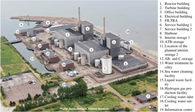
Barsebäck NPP consists of two adjacent nuclear reactors, B1 and B2, see figure 2-1 below. B1 and B2 are structurally joined via electrical buildings, control rooms and staff build-ings. Some process systems are common for both B1 and B2. As both B1 and B2 have a lot in common and have been shut down for such a long period, they are now considered to be one facility.
Figure 2-1. Barsebäck nuclear power plant. Note that no. 11, pointing out location of the planned interim storage 2, actually shows the goods reception building that will be demol-ished in favour of interim storage 2.
After final shutdown a lot of the buildings have been assigned a new or modified function and the majority of the process systems are shut down. The systems that will be operational during D&D are primarily ventilation, activity monitoring, fire protection, electrical power and security, as well as the systems needed for proper management of the waste and stor-age of radioactive waste.
Spaces where there is a risk of radioactive substances being discharged to water or air, or being transferred with goods or personnel to the environment are classed as controlled ar-eas for example spaces inside the reactor- and turbine buildings, the waste building and
ser-1. Reactor building 2. Turbine building 3. Office building 4. Electrical building 5. FILTRA 6. Service building 1 7. Service building 2 8. Harbour 9. Interim storage 1 10. ATB-storage 11. Location of the planned interim storage 2 12. AB- and C-storage 13. Water treatment
fa-cility
14. Sea water cleaning facility
15. Liquid waste facil-ity
16. Hydrogen gas pro-duction facility 17. Cooling water inlet 18. Cooling water
out-let
Status of the facility prior to D&D
Since the final shutdown a number of preparatory activities have been performed. For ex-ample, all nuclear fuel, all control rods and core probes as well as sampling rod chains be-longing to B1 and B2 were removed from Barsebäck NPP and sent to Clab. System decon-tamination of primary systems was performed 2007-2008, which resulted in significant amounts of the activity inventory being transferred from system surfaces to tanks storing used ion exchange resins. Many systems have been shut down during the C&M operation, as they are no longer needed for operational or safety reasons.
During 2006-2008 the facility’s electrical systems and control and surveillance systems were adapted to better suit the requirements during C&M operation. The changes also en-tailed the implementation of energy-saving measures. Considering the measures already implemented it is not envisaged that any major modifications of the facility are needed to facilitate operation and surveillance of the plant during D&D.
Radiological surveys has been performed and will continue during D&D.
In 2016 interim storage 1 was constructed to store the segmented reactor internals. Other low and intermediate level waste might be stored in interim storage 1.
Reactor buildings
Each reactor building consists of three main sections; reactor containment, storage and han-dling pools as well as the rest of the structure.
Each reactor building consists of 11 floor levels. The reactor containment, a cylindrical space, is located in the centre of the building. The top part contains the reactor together with ancillary equipment and the lower part contains the suppression pool. In the event of an abnormal situation occurring during operation the containment prevented discharge of activity to the environment.
The top floor of each reactor building contains the reactor hall with the storage and han-dling pools, which among others functions provided storage for irradiated fuel, control rods and the reactor pressure vessel head and dome during outages.
Other parts of each reactor building contain mainly adjacent process systems and service areas.
The foundation of each reactor building is located on top of firm moraine clay 13 m under the plant’s courtyard. The surface area above ground of each building is about 33 x 46 m and the height above ground is about 70 m, (110 m including the stack). The outer walls consist of aluminium-clad concrete.
Turbine buildings
Each turbine building consists of two main sections: the turbine section and the feed water preheating section.
Each turbine section contains mainly the turbine, condenser and generator while the feed water preheating section contains spaces for feed water preheaters, condensate polishing equipment and feed water pumps.
Each turbine building’s load-bearing pillar and wall foundations are located on firm mo-raine clay while the concrete floor foundation rests on packed gravel. The surface area
above ground of each building is about 86 x 53 m and the height above ground is about 32,5 m. The outer walls consist of aluminium and brick-clad injected polymer concrete.
Office buildings
The Barsebäck NPP also has office buildings, kitchen, staff canteen and buildings for the presentation of external information, which will also be used during D&D, for as long as they are needed.
Electrical buildings
Each electrical building is separated into 7 floor levels of which the three lowest levels contain cable spaces. Otherwise the electrical buildings contain spaces for electrical sys-tems such as batteries, switch gear and frequency converters as well as some offices. Each electrical building’s load-bearing pillars and walls are underpinned in sockets located in firm moraine clay while the concrete floor in the cable basement’s foundation rests on top of packed gravel. The surface area above ground of each building is about 90 x 28 m and the height above ground is about 22 m. The outer walls consist of aluminium and brick-clad injected polymer concrete.
Filtra
Filtra is a pressure relief and scrubbing system that has been shut down. The purpose of Filtra, in the event of an accident, was to protect the environment from radioactive releases. Filtra is a 40 m-tall tower, filled with 10’000 m3 of crushed rock and gravel.
Service building 1
In service building 1 there are facilities for handling, sorting and compacting solid waste and for separating waste oil, as well as a decontamination facility for tools, equipment and components. The radioactive waste is sorted according to waste category and radiation classification. The sorted and classified radioactive waste is sent to external facilities either for incineration, smelting or final disposal.
Harbour
The Barsebäck NPP’s harbour is located directly adjacent to the power plant area and is equipped with electrical supply for ships. The harbour is fenced and is subject to the same security requirements as the power plant. The purpose of the harbour is the handling of ra-dioactive waste in connection to maritime transport. The harbour can also handle other types of traffic such as vessels performing hydrographic surveys, moorings for rescue boats as well as other traffic important for the plant’s activities. The harbour is classified by the International Ship and Port Facility Security Code (ISPS-code). The harbour is classified as a civilian protected property by the county council of Skåne.
Interim storage 1
Interim storage 1 was constructed in anticipation of D&D of the whole plant in order to store segmented reactor internals until such time they can be transported to their final re-pository, which has been presented earlier in a separate Article 37 report, assessed by the Commission [2]. There will be remaining capacity in interim storage 1 even after the seg-mentation of reactor internals is complete, which means the facility can be used as interim storage for other radioactive waste.
The building consists of one floor divided into a main building (storeroom and anteroom for loading and unloading) and an auxiliary building (electrical room and office).
The main building is provided with dehumidification and heating equipment. The air recir-culates in this part of the building i.e. no emission point to the surroundings exist.
The auxiliary building is provided with conventional air-treatment equipment and has emission points to the surroundings.
The foundation of the main building consists of a heavily reinforced concrete slab with a surface area above ground of about 33 x 15,5 m, located at 3 m above average sea level. The structure consists of steel-clad and uninsulated thick concrete walls. The auxiliary building is a more conventional structure that is insulated and has a surface area above ground of about 11 x 4,5 m.
ATB-storage
Waste transport container, ATB, is a transport package for waste containers. The ATB-storage stores shipping containers and ATBs containing low and intermediate level waste awaiting transport to external waste treatment facilities or final disposal.
The building consists of one floor and it is provided with natural draft ventilation. The load-bearing walls are attached to a concrete slab, which is resting on top of packed gravel and moraine clay. The surface area above ground is about 41,5 x 10 m and the height of the building above ground is about 6 m.
AB- and C-storage
The AB- and C-storage were designed to provide radiologically protected storage for short-lived low and intermediate level waste. The walls and other structures of the building func-tion as radiafunc-tion shielding as well as load-bearing elements. The ventilafunc-tion funcfunc-tions in-clude dehumidification and maintaining a comfortable working environment. The air in the handling spaces and the storage compartment is recirculated. Solid waste is stored in the AB-storage, for example solidified ion exchange resins. The waste is stored in concrete moulds and placed in cells covered with radiation-shielding concrete blocks. Steel drums containing low and intermediate level waste and scrap metal are stored in the C-storage. The C-storage is also used to store concrete tanks filled with filter waste/ion exchange res-ins pending transportation. The waste is stored pending further external conditioning or fi-nal disposal. The surface area above ground is about 30 x 80 m and the height of the build-ing above ground is about 13 m / 9,5 m.
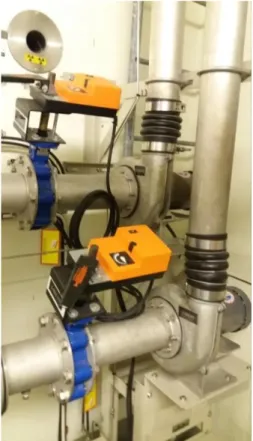
Sea water cleaning facility
There are two sea water cleaning facilities at the Barsebäck NPP with the function to screen sea water. The screening plant for B1 has already been shut down. At B2 one cool-ing water pump is intermittently operated durcool-ing C&M operation in order to provide en-hanced flow when treated wastewater is discharged to Öresund. Only limited amounts of debris arise during these short periods of operation.
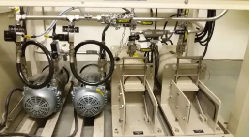
Liquid waste facility
A common liquid waste facility at the Barsebäck NPP treats different streams of radioac-tive water. The liquid waste facility is a freestanding building where radioacradioac-tive effluents and discharged ion exchange resins are transported via piping. The facility separates the solid component and purifies the water. After sample approval the water is pumped out to sea.
Cooling water inlet and outlet
The cooling water was extracted from Öresund via the harbour and a common intake canal to the facility. The intake canal is situated south of the NPP. The cooling water was dis-charged to the west of the NPP. As during C&M operation, there is no need for cooling wa-ter during D&D as all of the fuel has been removed. During C&M operation, one cooling water pump is intermittently in operation for other reasons, see sea water cleaning facility above.
Other buildings
There are stores, workshops and warehouses to facilitate service and maintenance of the Barsebäck NPP. The laundry facility used to wash protective clothing in the controlled area was shut down in 2009. The laundry is currently transported to an external laundry facility. There is a hydrogen production plant located at the Barsebäck NPP. During power opera-tion hydrogen gas was added to the reactor coolant in order to reduce the risk of stress cor-rosion cracking of the reactor piping by reducing the amount of free oxygen in the coolant. The hydrogen plant has not been used during C&M operation and will not be used during D&D.
There are two natural gas fired boilers, one primary and one reserve, to heat the facility. For production of hot water there are electrical water heaters placed around the facility. The Barsebäck NPP onsite water works distribute potable water, water for fire hydrants and water for production of process water. Incoming water is potable water from Kävlinge mu-nicipality. The process water used at the facility is deionised and produced at the Barsebäck NPP in the water treatment facility.
Ventilation systems and the treatment of gaseous and
air-borne wastes
There are separate ventilation systems for B1 and B2, servicing different spaces. One sys-tem is dedicated to non-controlled areas and one syssys-tem is dedicated to controlled areas. Spaces within controlled areas include the reactor, turbine and waste buildings, service building 1, parts of the electrical buildings and parts of storage areas. These spaces are ven-tilated through separate ventilation systems, where directed ventilation guides the air to the atmosphere via the ventilation stacks installed on B1 and B2 as well as service building 1. As BKAB has removed all fuel from the site, SSM has granted an exemption [6] regarding the requirements for continuous nuclide-specific measurement of noble gases, nuclide-spe-cific measurement of iodine sampling, as well as carbon-14 and tritium in discharges to at-mosphere. The analyses currently performed on atmospheric discharges are nuclide-spe-cific gamma measurements on aerosols collected on sampling filters integrated weekly, see section 3.3.
Discharge of radioactive substances from the Barsebäck NPP to air is monitored by sam-pling at the discharge points:
main ventilation stacks on top of the B1 and B2 reactor buildings,
The atmospheric discharges from controlled areas are monitored by continuously diverting a small portion of the airflow over a sampling filter for aerosols. Sampling filters are ana-lysed once per week for radioactive substances.
Sampling volume and discharged air volume are measured and recorded in order to calcu-late the total discharge of radioactivity to the atmosphere.
Figure 2-2. Schematic of the ventilation systems at B1before reconstruction during D&D Currently the air extracted from the waste building is led to the atmosphere via the turbine building at B1 and main ventilation stack on top of B1, see figure 2-2. During D&D the ventilation of the waste building will be modified. By separating the waste building from the reactor and turbine buildings at B1 interdependency between these buildings and the waste building’s ventilation requirements will thus be eliminated during D&D.
It is possible a mobile ventilation system may be required for a short duration during dis-mantling of current ventilation equipment.
The interim storage 1 (main building) and AB- and C-storage are not provided with exhaust air ducts, the indoor air recirculates. The ATB-storage is provided with natural draft venti-lation.
Liquid waste treatment
B1 and B2 share a common liquid waste treatment facility to manage radioactive water. The liquid waste facility is a freestanding building, see figure 2-1. The purpose of the facil-ity is to separate the solid fraction and purify the remaining water as well as discharge the purified water to Öresund after approved sampling. During C&M operation a cooling water pump at B2 is used for discharge in order to fulfil the mixing requirement for discharging water from the waste building. During D&D this pump will be disconnected. The radiolog-ical effect from the reduced mixing flow has been investigated and reported [7]. The as-sessment is that the reduced mixing flow does not have any significant radiological effect to humans or the environment.
During power operation about 50’000 m3 of water was processed annually. During C&M
operation the amount has decreased to about 2’000 m3/year. During D&D this number is
expected to decrease even further, especially after all the storage pools have been emptied of water. Sedimentation in tanks therefore becomes more efficient as the flow rates are low. Barsebäck does not have any laundry facility on site and furthermore the use of chemicals has been minimised and the use of strong complexing agents is prohibited within the con-trolled area. Altogether this results in high efficiency of the ion exchange filters (resins). The radioactive water’s origins and composition do differ. In order to facilitate an efficient treatment the waste facility is subdivided into different trains. A schematic overview is shown in figure 2-3.
Figure 2-3. Schematics of the waste facility, train 1-6.
Train 1 System drains from reactor buildings.
Train 2 Floor drains from reactor- and turbine buildings as well as service building 1. Train 3-1 Ion exchange resins from systems for purification of storage pool water. Train 3-2 Water from floor drains and decontamination systems.
Train 4-1 Precoated filters and ion exchange resins from the waste treatment facility. Train 4-2 Beaded ion exchange resins from the waste facility.
Train 5 Evaporator – train 5 is not in operation. Train 6 Floor drains from the waste facility.
Train 7 Train for management of ion exchange resins and particular pollutants from train 3 and train 4.
Abbreviations:
F Precoat filters for capture of particulates.
I.E.-1 Deep bed ion exchangers containing beaded ion exchange resin. M.F: Membrane filter for capture of particulates > 1 nm.
I.E.-3 Deep bed powder ion exchanger for capture of ions and particulates and silt from floor drains. The purification step is performed in a concrete tank with dewatering.
Train 1: In tank T11 water for purification from the reactor building’s system drains,
in-cluding storage pool water, is collected. Purification is performed intermittently in a recir-culating purification system composed of filters and ion exchangers. The water is purified to low activity levels before it is transferred to discharge tanks T22 or T23.
Train 2: Water from floor drains within controlled areas comes from spaces within the
re-actor building, turbine building as well as service building 1. The water is directed to the waste facility for treatment. After sedimentation and filtering the water is led to the dis-charge tanks T22 or T23.
Train 3-1: In tank T31 spent powdered ion exchange resin from systems for purification of
storage pool water is collected. The clear phase in the tank is allowed to settle before the water is pumped to T73. The activity in T73 is concentrated by membrane filtration. The permeate is pumped to discharge tanks, while the concentrate is intermittently returned to T31. Powdered ion exchange resin is transferred to tank T72 in train 7.
Train 3-2: T32 is used as a settling tank for contaminated process water. The clear phase
in T32 is directed via T41 to concrete tanks (I.E.-3) containing spent powdered ion ex-change resin from the condensate polishing system. After purification by the concrete tank’s powdered resin the water is moved to discharge tanks T22 or T23. The sediment in T32 is moved to T33 which is intermittently emptied into the concrete tanks.
Train 4-2: T42 is a buffer tank for beaded ion exchange resins from the reactor buildings
and the waste facility’s ion exchange resins from train 1. The clear phase from T42 is trans-ferred to T32. Ion exchange resins are transtrans-ferred to tank T72 in train 7.
Train 6: In tank T61 system- and floor drainage from the waste facility is collected. The
drainage is directed towards the concrete tank via T32 and T33.
Train 7: In tank T72 ion exchange resins are collected to be grouted into 200-litre barrels.
Surplus water from T72 is returned to T31.
From the discharge tanks T22 and T23 discharge to sea is conducted intermittently after ac-tivity measurements. During the discharge a proportionate sample is extracted for legal sampling in T25. See further information in section 4.3.
In summary regarding treatment of liquid waste:
Purification of water is performed by: o Sedimentation
o Recirculated filtering of water in tank T11 o Membrane filtering of highly contaminated water
o Filtering of water with lower level of contamination in concrete tanks with powder form ion exchange resin.
Transported out from the waste facility are: o Purified water to sea
o Concrete tanks containing low level dewatered powder form ion exchange resin and silt
Solid waste treatment
This section describes the treatment methods for solid waste, both on and off site. There is also a description of the different storage facilities and capacities on site. For further infor-mation regarding the continued waste management process, intermediate storage and final recipient see chapter 5.
Radioactive waste generated during D&D intended for final repository is managed in such a way to fit the system for dealing with Swedish radioactive waste, see appendix 2. The Swedish system includes cooperation with SKB and common solutions to meet require-ments with respect to waste management, packaging, transport and final repository in SFR and SFL. Since neither SFR for decommissioned waste nor SFL are constructed, it is planned for interim storage of waste on site in the meantime.
2.4.1. Treatment at site
Collecting and sorting
Waste should be sorted, to the greatest possible extent, as close as possible to where it is created or to the decommissioning site. The waste is sorted according to origin, material type and activity. Activity is assessed through characterisation and measurement. Also haz-ardous waste is characterised in order to be free released in accordance with SSM’s regula-tions for free release. If free release is not possible the waste is disposed in SFR according to agreements with SKB.
Radioactive waste is sorted with regard to waste category and final recipient, see table 2-1. Table 2-1. Overview waste categories
Category Surface dose rate
[mSv/h]
Planned final recipient
Materials possible to free release.
Not applicable External recipient
Materials for free release (metals) and combustible material.
< 0,1* To be used in other industry, external recipient
VLLW ≥ 0,1 - < 0,5 Surface repository, SFR
LLW ≥ 0,5 - < 2 SFR
ILW > 2 SFR/SFL
Waste to be exempt, free released
Free release of materials will be performed continuously during D&D. The purpose of free release is to minimise the quantities of radioactive waste that require final disposal. The materials can be free released immediately or after treatment, such as decontamination. If the material cannot be decontaminated it is managed as radioactive waste. BKAB will set up a free release facility on site for free release measurements during D&D.
Handling of Short lived very low level and low level waste (VLLW and LLW)
The waste consists of trash and metal scrap with a surface dose rate <2 mSv/h. The waste is compacted if possible. Waste is placed in a shipping container for interim storage or buffer storage pending transportation to external recipient.
Short lived intermediate level waste (ILW)
Solid waste in the form of garbage and metal scrap with a surface dose rate >2 mSv/h is sorted at the dismantling site and collected into a steel or concrete box.
Handling of segmented Reactor internals and Long-lived low and intermediate level waste (LLW and ILW)
Reactor internals from the reactor pressure vessels have been segmented and packaged into steel tanks. Long-lived low and intermediate level waste trash and scrap metal are pack-aged into concrete moulds with bolted lids. The waste packages are designed for final dis-posal at SFL and will initially be placed in interim storage at the Barsebäck NPP. Interim storage at an external site may be possible.
2.4.2. Treatment off site
Smelting
Smelting of metal is a method that can be used in order to achieve a homogenous distribu-tion of activity in materials were different nuclides may not be separated out. Another ad-vantage with smelting is a reduction of the waste volume.
When smelting is feasible, low level metal scrap will be sent to an approved external facil-ity for smelting and free release of the resulting ingots or final disposal if required.
Incineration
During decommissioning low level combustible waste will be created such as plastics, cleaning and personnel protection equipment. Combustible waste is sent to an approved ex-ternal facility for treatment (incineration). If the criteria for incineration cannot be met the waste is sent for final disposal.
Both smelting and combustion are used to a lesser degree for waste management during C&M operation.
2.4.3. Package
All radioactive material and waste is placed and transported away in approved waste pack-ages, in accordance with the Swedish transport agency’s and the Swedish civil contingen-cies agency’s regulations [8], [9] and [10] and waste acceptance criteria stipulated for each final recipient.
2.4.4. Storage on site
In order to achieve an efficient a decommissioning logistics process, the flow of waste and waste packages needs to be as unimpeded as possible. Certain decommissioning stages could be more time-consuming than others and in order to maintain a smooth flow there is a need for buffer storage and interim storage facilities. Existing storage together with the proposed new storage space, interim storage 2, are estimated to have sufficient storage ca-pacity based on the plans for the demolition and disposal of the waste. Storage spaces are designed to achieve well-functioning radiation protection for both staff and environment, and are located in controlled areas.
Existing storage
AB- and C-storage
Existing storage in which operational waste in containers such as steel drums and concrete moulds are stored. Operational waste is to be transported to SFR. The aim is to demolish the AB- and C-storage at the same time as the buildings in the power plant area are demol-ished, but for as long as they remain they will be used as a storage location for the waste logistics at the Barsebäck NPP. The AB-storage refers to short lived intermediate-level waste in steel- or concrete moulds to be stored. In the warehouse there is space for about 1000 boxes. In the C-storage it is possible to store containers with low level waste. ATB-storage
The ATB-storage is used as a storage location for ATBs (waste transport containers) and shipping containers before transportation to SFR or other recipient. The ATB-storage can also be used for storing equipment that requires protection against the elements. The ATB-storage will remain during decommissioning and dismantling. In the ATB-storage there are place for 10 ATBs or about 40 containers.
Interim storage 1
An existing storage facility used today for storing the reactor internals packaged in steel tanks. The reactor internals consist of long-lived waste destined to be disposed of in the re-pository for long-lived waste, SFL. The interim storage 1 is planned to be used during de-commissioning and dismantling for storage of short-lived intermediate level waste stored in, for example, steel- or concrete boxes. The Interim storage 1 is designed for 120 steel tanks. Segmentation of reactor internals is expected to generate about 70 steel tanks. The storage facility will remain in place until the waste can be transported to SFR or SFL or to external interim storage.
Planned storage
A new interim storage facility constructed for decommissioning waste. The storage facility is planned to be built close to the already existing interim storage 1. The interim storage fa-cility is primarily for storing shipping containers loaded with short-lived low level waste. The interim storage can also be used as a location for storing large components and ship-ping containers with waste that are to be sent to an external recipient. The storage will re-main in place until SFR is extended and ready to receive the waste.
The planned new storage facilities will be designed to together with existing storage facili-ties to have sufficient storage capacity according to the existing plans for the decommis-sioning and shipping of waste.
Buffer storage
Buffer storage refers to places for temporary storage of waste. Temporary storage of radio-active waste may be required pending continued management of the waste on site or pend-ing transportation to external storage, external surface repository or to external treatment. Identified areas for buffer storages are:
Areas within the turbine buildings (e.g. turbine halls and pump/preheater halls)
AB- and C- storage
ATB-storage
Area adjacent to where waste management is performed
Interim storage 2
Containment
Containment is the term describing the protective measures used at the Barsebäck NPP to contain radioactive substances.
During D&D, as well as during C&M operation, only the outer shell barrier is utilised. Other barriers that were credited during power operations, such as fuel, fuel cladding, pri-mary system and reactor containment, are not applicable during D&D. The outer shell bar-rier is defined by SSM as “Physical obstacle that directly or indirectly counteracts the dis-tribution of radioactive substances”.
It is normally the building walls that fulfil the outer shell barrier function to prevent exter-nal discharge. Not until a discharge reaches outside the building, the barrier is considered breached.
The outer shell barrier function is also provided by tank cells, tanks, piping and contain-ers/waste packages with respect to internal discharges that may affect personnel. Not until these are compromised and personnel risk exposure to radiation, the barriers are considered breached.
In order to clarify the overview of requirements for a facility in D&D, BKAB uses the terms protective function, requirement function and requirement system.
In figure 2-4 the relationships between these terms are shown in order to describe how they ensure that the outer shell barrier is maintained.
Barrier
Protective function Requirement function
Req. system
Protective functions are tasked with maintaining barriers to protect the environment and
personnel against the dissemination of activity and include:
Fire protection
Protection against unauthorised access
Protection against flooding
Monitoring of radioactive discharges
Requirement functions are the system functions required to fulfil a protective function,
i.e. acceptance criteria regarding the integrity of the barrier and discharge of radioactivity to the environment and within the plant, which should be applicable for the Barsebäck NPP during D&D in order for the facility to fulfil the requirements for a safe facility. The re-quirement functions include:
Radioactive discharge and monitoring
Waste management
Firefighting and blowing paths
Facility security
Floor drains and drainage paths
Ventilation and sealing of buildings
Requirement systems’ main purpose is to, possibly together with other requirement
sys-tems, fulfil a certain requirement function.
Operating systems denotes those system functions with operational assignments that
should remain during D&D, including supplying the system functions. Systems with opera-tional assignments include service systems, power supply, control and surveillance.
Interim storage 2
2.6.1. Main features of the installation
BKAB will build a new building, interim storage 2, for interim storage of primarily short-lived very low level waste (VLLW) and short-short-lived low level waste (LLW), but other radi-oactive waste, such as large components, may be stored in the building.
Interim storage 2 is to be constructed in the harbour area, 3,0 m above sea level, close to the existing interim storage 1. Prior to construction, existing goods reception building must be demolished according to applicable requirements. The main purpose of locating the in-terim storage facilities close to the harbour is to facilitate the logistics during transportation of the waste by boat, as well as to enable the area to be limited when only the interim stor-age facilities remain at the site.
Interim storage 2 will only be used as a storage space and the capacity will be adapted as required. Applicable building rules shall apply and the following safety principles will ap-ply for the interim storage 2:
![Table 1-3. Wind frequency and wind direction at Barsebäck NPP (1987 - 1992). Speed [m/s] N NE E SE S SW W NW Cumulative 0,5-2,5 2,0 2,1 3,6 1,5 1,5 1,0 1,5 1,9 15,1 2,5-4,5 2,4 2,3 4,5 2,6 2,8 2,6 3,4 3,2 23,8 4,5-6,5 1,7](https://thumb-eu.123doks.com/thumbv2/5dokorg/3336394.18323/21.892.148.772.180.453/table-wind-frequency-wind-direction-barsebäck-speed-cumulative.webp)

![Table 3-2. Total activity in buildings at Units B1 and B2 [14] (Ref. dat. 2019-01-01)](https://thumb-eu.123doks.com/thumbv2/5dokorg/3336394.18323/47.892.139.808.135.1113/table-total-activity-buildings-units-b-ref-dat.webp)
![Table 3-5. Prognosis of activity emissions to air from B1+B2 during decommissioning [22]](https://thumb-eu.123doks.com/thumbv2/5dokorg/3336394.18323/49.892.153.825.747.1010/table-prognosis-activity-emissions-air-b-b-decommissioning.webp)
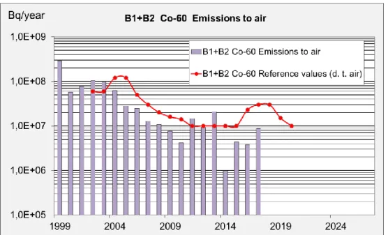
![Figure 3-2. Reference values, emissions and prognosis of Co-60 to air from B1 and B2 [22]](https://thumb-eu.123doks.com/thumbv2/5dokorg/3336394.18323/50.892.149.702.125.461/figure-reference-values-emissions-prognosis-air-b-b.webp)