·Form 164.
CURRENT METER NOTES.
BOOK No:·---~---·
IRRIGATION INVESTIGATIONS. U. S. DEPARTMENT OF AGRICULTURE,
BUREAU OF PUBLIC ROADS. 8- 194
RATDfG TABLE, GURLEY CURRENT METER NO. 15,188
r~y 14, 1 9 3 2 V
=
2.192 R + o. 020----~~--~--~~--~-~---~----~----~~-~---~-~~~--~~--~---~----~~~--~-~-~-~~~~----~
Revs. Revs.
per o.oo o.o1 o.o2 0.03 0.04 0.05 o.oe o.o7 0.08 0.09 per
Sec. Se('.
Velocity in Feet per Second
o.o •••• 0.04 0.05 0.09 o.]J. 0.13 0.15 0.17 0.20 0.22
o.o
o.1 0.24 .26 .28 .30 .33 .35 .37 .39 .41 .44 o.1 0.2 .46 .48 .50 .52 .55 .57 .59 .61 .63 .66 0.2 0.3 .68 .70 .72 .74 .76 .79 .81 .83 .85 .87 0.3 0.4 .90 .92 .94 .96 .98 1.01 1.03 1.05 1.07 1.09 0.4 0.5 1.12 1.14 1.16 1.18 1.20 1.23 1.25 1.27 1.29 1.31 0.5 0.6 1.34 1.36 1.38 1.40 1.42 1.44 1.47 1.49 1.51 1.53 0.6 0.7 1.55 1.58 1.60 1.62 1.64 1.66 1.69 1.71 1.73 1.75 0.7 o.8 1.77 1.80 1.82 1.84 1.86 1.88 1.90 1.93 1.95 1.97 o.8 0.9 1.99 2.01 2.04 2.06 2.08 2.10 2.12 2.15 2 .1'1 2.19 0.9 1.0 2.21 2.23 2.26 2.28 2.30 2.32 2.34 2.36 2.3~ 2.41 1.0 1.1 2.43 2.45 2.48 2.50 2.52 2.54 2.56 2.58 2.61 2.63 1.1 1.2 2.65 2.67 2.69 2.72 2.74 2.76 2.78 2.ao 2.83 2085 1.2 1.3 2.87 2.89 2.91 2.94 2.96 2.98 3.00 3.02 3.04 3.07 1.3 1.4 3.09 3.11 3.13 3.15 3.18 3.20 3.22 3.24 3.26 3.29 1.4 1.5 3.31 3.33 3.35 3.37 3.40 3.42 3.44 3.46 3.48 3.50 1.5 1.6 3.53 3.55 3.5'7 3.59 3.51 3.54 3.66 3,68 3.'70 3.72 1.6 1.'7 3.75 3.77 3.79 3.81 3.83 3.86 3.88 3r9o 3.92 3.94 1.7 1.8 3.95 3.99 4.01 4.03 4.05 4.07 4.10 4U-2 4.14 4.16 1.8 1.9 4.18 4.21 4.23 4.25 4.27 4.29 4.32 4.34 4.36 4.38 1.9 2.0 4.40 4.43 4.45 4.47 4.49 4.51 4.54 4156 4.58 4.60 2.0 2.1 4.62 4.65 4.6'1 4.69 4.71 4.73 4.75 4.78 4.80 4.82 2.1 2.2 4.84 4.86 4.89 4.91 4.93 4.95 4.97 5.00 5.02 5.04 2.2 2.3 5.06 5.08 5.11 5.13 5.15 5.17 5.19 5.22 5.24 5.25 2.3 2.4 5.28 5.30 5.32 5.35 5.37 5.39 5.41 5.43 5.46 5.48 2.4 2.5 5.50 5.52 5.54 5.57 5.59 5.61 5.53 5.65 5.68 5.70 2 1::; •
J
2.6 5.72 5.74 5.76 5.78 5.81 5.83 5.85 54187 5.89 5.92 2.6 2.7 5.94 5.96 5.98 6.00 6.03 6.05 6.07 6J09 6.11 5.14 2.7 2.8 6.16 6.18 5.20 6.22 6.24 6.27 6.29 5t~31 5.33 6.35 2.8 2.9 6.38 6.40 6.42 6.44 6.46 6.49 6.51 6.53 6.55 6.57 2.9Jolet
1 I -v GAGING OF---;---'--- ---DATE,---, 19____ METER NO.--- ~---GAGING MADE BY ---~-~--- ---Dist.from initial point. Checked by Depth of water. Contfit un f clnl.nnel, Method of gaging, '("' Rema(JP;I t Depth of observation. Time in seconds. ~VELOCITY. t § - - -<l)O -~5l AT---
...&J
v
!2~! ____/_:J..
---------~t1t,...,
-~------------------~MEASUREMENT BEGAN ..:\.T --- GAGE HEIGHT
{I.
I.--Canal
---GAGE HEIGHT { I. L ______ _
Canal ---,.,
Discharge.
If.
!Jde Fell iGp l tj-:J-1..-...--/Jlfl./1 a-~"~
r
'/• S''--
6..-,,
-1·:5~1 /'-I t..f '1 t...o g 0
GAGING OF---DATE,---, 19____ METER
NO.---GAGING MADE BY
---Dist. from Depth of Depth of Time in initial point. water. observation. seconds.
Computed by Checked by Condition of channel, Method of gaging, Remarks: ~ ~VELOCITY. j ; ; § -~ -~ At point. AT ---_______________ --- ____ ---~ MEASUREMENT BEGAN AT--- GAGE HEIGIIT
{I.
I.---~ Canal ---GAGE HEIGHT {I.I.---Canal ----~
I
GAGING OF
---:r---DATE, --~--(.l/._f.:::! _ _t .. _:_ __________ , 19____ METER N 0.---Dist. from Depth of Depth of Time in initial point. water. observation. seconds.
s
so Ll< 50 I· liD.a
5"0'·'¢
50 ).I J I I '2 .50 f.J3 50 t,\"1-50 1;'5 J.lb .S':l •' .:fO f,f::J .J$ Computed by1-1
Checked by l·SS~ Condition of channel, 1·55~ ?\ (.., Method of gaging,D·<SLj
a-
},4 ~ 4', J('J Remarks: I I 0-1
(. '-1s
tS" 4',q3 .:2- I.S4-I 1·1-{s
5 s.·o~AT---
o:f:t~Q
_
(;!
_______~
-
~
-
!':
_
i_LQ~
---~
MEASUREMENT BEGAN AT __ 4 .. 'Q_ ______ GAGE HEIGHT{I.
I.--Canal ---MEASUREMENT ENDED AT --- GAGE HEIGHT (I.
I.---l Canal ---VELOCITY. Area.
l2o-z£
;.h., I 1 .t I I ~? Mean depth. Width. (o/0 .:J 11.)-Discharge; /.S3.L/ ._GAGING
OF--DATE,---, 19____ METER N 0.
---GAGING MADE BY ---·---
---Dist. from Depth of Depth of Time in
initial point. water. observation. seconds.
6 ~-d VELOCITY. ~~ r ; § -Q> 0 <1l 0 ~~ ~~ Computed by Checked by Condition of channel, Method of gaging, Remarks: ~~~ ';).1 AT---'-·=-· ---MEASUREMENT BEGAN AT--- GAGE HEIGHT
{I.
I.---Canal
---MEASUREMENT ENDED AT--- GAGE HEIGHT {I.
I.--Canal
---VELOCITY.
Mean in
section.
Area. depth. Mean Width. Discharge,
GAGING OF--- .,---DATE, ---• 19____ METER NO.---·-GAGING MADE BY
---Dist. from Depth of Depth of Time in ·
initial point. water. observation. seconds.
Computed by Checked by Condition of channel, Method of gaging, Remarks: ~ ':'.,j VELOCITY. ~§ -~ -~ At point. AT---~
MEASUREMENT BEGAN AT--- GAGE HEIGHT {I.
I.---Canal
---Area. depth. Mean
GAGE HEIGHT { I. I.
---Canal ----~
5
DATE, ____ j_ ___________ /_ __________ , 19____ .METER N 0. ---~----_(_ ____ $_ ____ _
/
Dist. from Depth of Depth of Time in
initial point. water. observation. seconds.
/ Computed by /~ / -/73 Checked by / /. /35"' Condition of channel, / - / Method of gaging, Remarks: I /./8~ U'•.:C/ 7 /· / S,Y /· .21 '"I /• 18"1 .~ / • 2 / 8 /o / 3'.::;-_E • ~ • VELOCITY. ~~ ~§ -~:3 ~ ~ At point.
-r.
/~~'? ~-Y~ -¥ /-::r, .j", ? .1. .z~ P.l'f. AT---.:_ __ : ________ ~MEASUREMENT BEGAN AT ___ .:.~f~-~-- GAGE HEIGHT
{I.
I.---:--Canal
---.MEASUREMENT ENDED AT _:[._~;it-"~'- ·GAGE HEIGHT {I.
I.--Cnnal ---VELOCITY. Area.
11q
l,'2J~1{b/,1v
.Meandepth. Width. Discharge.
sq-z.
ID1
GAGING OF---·
---DATE,---, 19____ METER
NO.---Dist. from Depth of Depth of Time in
initial point. water. observation. seconds.
I I
I
~
I
[~ / · ,I,II
/I .z $C .8 sot.o
'
I
/I .·~ --:3:~ sor:.r
urr
#. h () 6'0 I Computed by phecked by Condition of channel, Method of gaging, Remarks: AT --- __ --- _ --- __ ---~--- ---~ M EA UREME T BEGAN AT---S N --- GAGE HEIGHT {I. I.---Canal ---MEASUREMENT ENDED AT--- GAGE HEIGHT f I.I.--- I.--- l Canal ---VELOCITY.
GAGING OF---=---DATE,---, 19____ METER
NO.---j! Computed by Checked by Condition of channel, Method of gaging, Remarks: AT---.,.---:
S EN GAGE HEIGHT
{I.
I.---~MEA UREM T BEGAN AT---
Canal---4·77)
4
.D}7
---
1
I 7.q ...]·
Mean depth.
GAGE HEIGHT {I.
I.--Canal ---Width. 1.5tJ • ?.. -.'2
4·
3S
6-o
,,
Discharge.GAGING OF---
---DATE,---, 19 ___ ~ METER
NO.---GAGING MADE BY
---Dist. from Depth of Depth of Time in
initial point. water. observation. seconds.
b ~ VELOCITY.
~~ ~§ -~:3 ~ ~ At point.
AT---..!'---~---~
GAGE HEIGHT
{I.
I.---MEASUREMENT BEGAN AT--- _ Canal
---Mean
depth.
GAGE HEIGHT
{I.
I.--:Canal
GAGING 9F
---DATE, __ j_ ___ l_j __ 2 _Q _________ , 19 __ ?- METER No. _L§i_l_$_ _______ _
Dist. from Depth of Depth of Time in
initial point. water. observation. seconds.
Computed by Checked by r Condition of channel, 1 , Method of gaging,,., ~ ;l 7 3 [....I ) } Remarks: <.... /, "'). 7 j fl~/0
o.
t. -L1.2-C ~ /)I/,-17
/,')..1 J ,')_ J 2.. /,:2/Z9
GAGE HEIGHT
{I.
I.---~ MEASUREMENT BEGAN AT ____ !________ Canal----~Area.
GAGE HEIGHT I.
I.---Canal ----~ Mean depth.
s.-Width. II ~0 Discharge.
GAGING OF---DATE,---, 19____ METER N 0. ---GAGING MADE BY ---Dist. from initial point. li.o J -1.9 Depth of water.
/
.
I
f
11vt/;
Computed by Checked by Condition of channel, Method of gaging, De-pth ofobservation. seconds. Time in
~ ~VELOCITY. ~§----CD<:.> p:j ~ At point. A'!' ---__________ _:
---MEASUREMENT BEGAN A'r --- GAGE HEIGHT
{I.
I.---Canal
---GAGE HEIGHT
{I.
I.---MEASUREMENT ENDED AT --- Canal
---VELOCITY. Mean in vertical.
II
,16 Dist.from initial point. Computed by;D .
Checked by Condition of channel; ;. J- £ Method of gaging, 1?..'
Remarks: .2-f /.')....(.
L;,,_~I
r
D GAGE HEIGHT{I.
I.---·MEASUREMENT BEGAN AT-----+--- Canal ---GAGE HEIGHT {I. I.---MEASUREMENT ENDED AT --- Canal
---VELOCITY. Area. ,, (J Mean
I
depth. Width.95,0'
I
Discharge. 5GAGING OF--- ---DATE,---, 1g____ METER N 0. --- --GAGING MADE BY --- ---Dist.from initial point. Computed by Checked by Depth of water.
Condition of channel, Method of gaging, Remarks:
Depth of
observation. Time in seconds.
... ~VELOCITY. ~§----<1>C.> ~ ~ At point. AT--- ---GAGE HEIGIIT
{I.
I.-~---MEASUREMENT BEGAN AT--- Cana ---GAGE HEIGHT { IC. I.-~---MEASUREMENT ENDED AT --- ana---VELOCITY.
Area. Mean in Mean in vertical. section.
Mean
Dist. from Depth of Depth of
initial point. water. observation.
Computed by Checked by Condition of channel, Method of gaging, Remarks: AT--- __ -· ---
---MEASUREMENT BEGAN AT--- GAGE HEIGHT {I.
I.--Canal
---Mean in section.
Area. depth. Mean
GAGE HEIGHT {I.
I.--Canal
GAGING OF---.,.--- ---_:---DATE, ---• 19____ METER NO.---GAGING MADE BY---.---;---
---Dist.from initial point. Computed by Checked by Condition of channel, Method of gaging, Remarks: b 1'3 o·!
.s:
'+9
--
1
3o3 lVELOCITY. AT---·-----:-· ___________________ ,. ___ _ MEASUREMENT BEGAN AT--- GAGE HEIGHT{I.
Canal __ I.---: __ MEASUREMENT ENDED AT--- GAGE HEIGHT {I.I.---Canal ____ _ VELOCITY. Area. Mean in Mean in vertical. section. Mean
Dist. from Depth of Depth of Time in initial point. water. observation. seconds.
~ ~ VELOCITY. ~~ ~§ -~:3 ~ ~ At point. I . Computed by
;-lcz_
1--1 b Checked by /t 3 ~~ Condition of channel, /.'
: J ~ Method of gaging, 1.,3(p () G' Jo
Remarks: lr3CP .2 (;·~/,359
11309 AT--- --- -----MEASUREMENT BEGAN AT ___ f_~]_ _____ GAGE HEIGHT {I. I.---
-Canal
---MEASUREMENT ENDED AT--- ____ GAGE HEIGHT {I. I.---
--Canal ---VELOCITY. Area. Mean in Mean in vertical. section.
Ve~
r ...
te9
ot
Jyteer
tJ.oqv=
2. ~ufo
7C::.
,b
2
Mean depth.(o
Width. I Discharge. /25' GcV' :2. '397
rGAGING
OF---:---DATE,---, 19____ METER
NO.---·GAGING MADE
BY---Depth of Depth of Time in
water. observation. seconds.
I
~
Computed by 1: Checked by Condition of channel, Method of gaging, Remarks: AT---·------MEASUREMENT BEGAN AT--- GAGE HEIGHT {I.
I.---Canal
---Mean in
section. Area.
GAGE HEIGHT {I. I.---
-Canal ---Mean I . depth. W1dth. Discharge.
3
~
\ '-\
~7
~(/
El
d
~
z
rr
tl VY1GAGING OF __ - ---- ---:JCTER NO. ___
L}_
__
Q
_c:). ___
_
I, initial point. Dist. from Depth of water. observation. Depth of seconds. Time in
53.0 So <:
G"lo
'1'1,3 .553
7~-F] .. &70
~ ~()2..77
5 ~ Computed by Checked by Condition of channel, Method of gaging, Remarks: .AT--- . •~--0 C...-
---~-
.:Jt;;i
__ 'd_§ __d.t::J~-
--"---
·
__ --- --MEASUREMENT BEGAN AT--
f-A
----
GAGE HEIGHT{I.
I. _,4_~-, Canal
---' 1' •
{I I
MEASUREMENT ENDED AT~-.. !-·--- GAGE HEIGHT . . __ .. __ _ Canal
---Area. depth. Mean Width.
I
Discharge.l
II
I
II
GAGING OF---~---~---.-DATE,---, 19____ METER NO.---GAGING MADE
BY---~-Dist. from Depth of Depth of Time in initial point. water. observation. seconds.
Computed by Checked by Condition of channel, Method of gaging, Remarks: ~VELOCITY. ~g -~ -~ At point. ~ T ---·--- -·
---MEASUREMENT BEGAN AT--- GAGE HEIGHT
{I.
I.--Canal
---MEASUREMENT ENDED AT --- GAGE HEIGHT
{I.
I.--Canal ---VELOCITY. Area. Mean in Mean in vertical. section. Mean
Dist. from initial point. Computed by Checked by Depth of water. Condition or channel, Method of gaging, Remarks: Depth of
observation. Time in seconds.
lg ~VELOCITY. j ( ; § -Q)O ~ ~ At point. AT---·---·---
---MEASUREMENT BEGAN AT-... ---~--- GAGE HEIGHT
{I.
I.--Canal
---MEASUREMENT ENDED AT--- GAGE HEIGHT{ I. I.---
-Canal ---VELOCITY. Area. Mean in Mean in vertical. section. Mean
GAGING OF---~---
---DATE,---, 19____ METER NO.---
---GAGING MADE BY ---
---~
':'-d !VELOCITY.
~~
-Dist. from Depth of Depth of Time in initial point. water. observation. seconds.
~~ Computed by Checked by Condition of channel, Method of gaging, Remarks: AT -r---·---·---· ---
---MEASUREM~NT BEGAN AT--- GAGE HEIGHT {I.
I.--Canal
---MEASUREMENT ENDED AT--- GAGE HEIGHT {I. I.--Canal
---VELOCITY.
Mean in section.
GAGING OF ____
7
/3
_
c
~
---
-(d_
_________2
_
Q_::
_
E_f
___
E(
_
~
_
j11
DATE, ____
lf-d.
_
j
_
y_
____
Q
_
L
,
19
~2y
ETER
No. ___ /_ __g_f
i:_l_
GAGING MADE BY _____
~
---
__s
_
kl
_
c~
-
~!L:
_____ ___
.£ ________~
--
1
1
Depth of Depth of Time inwater. observa.tion. seconds.
~-d VELOCITY. t l . l l : l -.;~ At point. Computed by /-fq_
T;nic
Checked by ,~4,CJz.
I,' S"o
-
;tjoa Condition of channel, . "' Method of gaging, Remarks:$
i46Cc.l -0~/2z:D
~4,
D CZ.. 3_9.;q ( 2 .. ':2lf
~40 ~ ~~9
6
2' ~ ~ 4·10~ 3.d
.2..<-' ... G.ll....L...b_ AT---·---· ______ :_ ________________ _ I ( -
{I.
I.---MEASUREMENT BEGAN AT-/-- __ ...._ __ --- GAGE HEIGHT
Canal---MEASUREMENT ENDED AT--- GAGE HEIGHT
{I.
I.----Canal ---VELOCITY. Mean in Mean in vertical. section. .._ 1- ./ (>. Area.
'}--9o·
-MeanGAGING 0 F
---DATE,--->---, 19____ METER
NO.---·---GAGING MADE BY---
---Dist. from Depth of Depth of Time in initial point. water. observation. seconds.
Computed by Checked by Condition of channel, Method of gaging, Remarks: b ~ VELOCITY. 'O,n ! ( ; § -~~ ~ ~ .At point. AT---·---·--·-·
---GAGE HEIGHT {I.
I.---MEASUREMENT BEGAN .AT--- Canal ---GAGE HEIGHT
{I.
I.----MEASUREMENT ENDED .AT --- Canal ---VELOCITY.
Mean in Mean in
vertical. section.
r
GAGING OF--- ---Dist. from initial point. Condition of channel, Method of gaging, Remarks: AT---·---·---MEASUREMENT BEGAN AT--- GAGE HEIGHT {~~:a~-~~~~~
MEASUREMENT ENDED AT ---
---VELOCITY.
Mean in vertical.
Area. depth. Mean
I. I. ---
l
. I I
GAGING OF __
_B
_
!
______
j__~ _____ j_:J__~_)___
1 ____________________ _· Of-~ ~~~~g
DATE, ---• 19____ METER NO. __ £ __________________ _
GAGING MADE BY
---
~~
--
:
--
-
---
1
---~---
_L~
_
'tf_l..t_
_______
_
Depth of Depth of Time inwater. observation. · seconds.
Computed by Checked by Condition of channel, Method of gaging, Remarks: .I
?.z
53 I~-~ -'-11.1; 4 ~.0 -'l -.c. 4-7, ~ ~s-.~ 4/a ,fl--4 ~h .q 2 ~ ~ VELOCITY. ~ ~ ~ § ...__ _ _ _ ~:3 ~ ~ At point. too l.f'~ 2. -6Cf / 1 t:IO 2p !oo 2,/~ I 0 0 2,.0~ I 0 D :2.n Ioo 1·1 (:, (0 I ((') 0 ./ 2o-
A
J:lu)/)
1
.
. .
AT---··---"'--- ··-··-·---,---MEASUREMENT BEGAN AT __ -~~--- GAGE HEIGHT { IC.
I.-~---ana
---11 I -4
s
/\._
{
I. I.---MEASUREMENT ENDED AT~- _: ______ .E-u-AGE HEIGHT I
Cana
---8.147
3./SZ-Area. depth. Mean Discharge.
)
GAGING
OF---DATE,---, 19____ METER
NO.---GAGING MADE BY ---
---Dist. from Depth of Depth of Time in initial point. water. observation. seconds.
::, ~ VELOCITY. '0..; ~ "'~ -§ ~ g ~:p ~ ~ At point. Computed by Checked by L .S 6 i Condition of channel, U
f
/1
'b 7 Method of gaging, 0 u.117 1 3f
Remarks:
.AT---··---·
---GAGE HEIGHT
{I.
I.---MEASUREMENT BEGAN AT--- Canal ---MEASUREMENT ENDEDAT---VELOCITY. Mean in Mean in vertical. . section. Area.
9/ lo
Meandepth. Width. Discharge.
1-1 w
@
H4.. 3.14q .tf7V. qDev
(r, Lt. tJ
11
~.9GAGING 0 F -.---~~·-·-:_---~---DATE,---, 19____ METER NO. _____ : _______________ _
Dist. from Depth of Depth of Time in initial point. water. observation. seconds.
.... ~ ~ VELOCITY. ~~ ~~----~:;::1 ~ ~ At. point. F=r=~-F~F===~~==~~~~
'I
l
1 Computed by Checked by Condition of channel, Method of gaging, Remarks: AT---: GAGE HEIGHT{I.
I.---MEASUREMENT BEGAN AT--- Canal---R M GAGE HEIGHT
{I.
I.---MEASU E ENT ENDED AT --- Canal ---VELOCITY.
Mean iD. Mean in
vertical. section.
L-e. c::. I..::. on Jol<t ; .. :r,
;c.,
r1cr.,
r
~~ 2 1 cF.o
yt-1
lv/
1j
()1
if.~
?. -
I""
(tO
j -
·::z4 '
03C(,
Largo Parshall Flume. Dear Ralph;
Difference in denaity of water in your two wells might have caused the seeming paradox of higher Hb gage tl~n Ha gage BUT IT DID NOT. All you had was almost complete sub mergence under a dynamic condition so that your recove~ of velocity head put the second gage higher than the first one.
lfNITED STATES DEPARTMENT OF AGRICULTURE
BUREAU OF AGRICULTURAL ENGINEERING
DIVISION OF IRRIGATION 222 PosT OFFICE BUILDINQ
BERKEI..EY, CALIF.
MAIL ADDRESS; P. 0. Bo~ 180 August 3, 1932
Mr. R. L. Parshall
olorado Agricultur 1 Exper~ent Station Fort Collins, Colorado.
VIA AIR
.AIL
D ar Mr. P rshall.
During the pest e k we have been giving considerabl study to the Parshall measuring flume and especially to the Bijou and Holbrook flumes.
1~. Scob y bas ade a good many analyses of the flo under different set-ups and has apparently hit on a solution of your troubles with th Bijou flume. There is ncloaed a memorandum covering his analyses.
In this connection it occurs.to me that if, at the close of the season, the ater could be run in the Holbrook flume and some temporary obstruction put in the canal belo the flumet
. which would tend to cut off the flow and bring th ater level above and belo th flume to the same elevation, you ould then hav a condition such as you no have in the Bijou flume. If thi
is not possible, I suggest you set up a model and try it out, that we may demonstrat Mr. Scobey's theory.
It may be that ith a model e could duplicate the mos
condition by artificial reeans rather than to use an obstruction
in the channel.
Very truly yours,
Division of Enc.
100 per cent submergence,head and tail waters is no flow,hence we must deduct from FREEFLOW Q
to he deducted from Freeflow
~lume the ratio of freeflow
100
f) rt3'~!:~.~..~T:D ..,'40~; D.t' 1·~, ; )- oot
- -
---~-~~~~~~~~~~~~~~~~ ':est 'a A~ ~0 " fl"'i ·hs
.
, ·0 )., ~ .te '· Diff. Dell' • ;..
·eet fee \.,; l..;(~C ... per ::~ee .. - S0t.,-
l".li. ce1t ~ • _ __._...,.w-_.,..._ ... ...--.. -... ...,.~-.-... ... ...._ ... _ _ _ _ _ _ _ _ _ . r • .l t • 1 7/12 ll.50 A l._P(7 1 •. )79 lr.a. ~ 1s
.
s
1: - ~2 •. 5 '/.1,; \I.
'· ~ t/12 ~ ... tA!> ,. ,ti IV ll.J r 2 ... OOP 1 .4~.7 -~ ._.'2.7 ·:.1~"' ,. 11 106.1 11 2 (_ .. t..6\. -!.t 7/J.~7
.
JO
P
l .-1,£:7 1.r
.
?o
'3 ·tl 1 ".11"'' 9 t. l, 21 -~ l l 10.: .6 1~!.4 .J-1.7 +·1·: v /.; 7/1'5 4.0r;4.
s
..
l;7 1.':6'' 3 lf.. l 9.6 1"' r 4 1.~ • -.'1 5 7/1'7 .:: • .1QP --218 1.1~5ee
.ro~ 10:1. 'Y .L:;•
G
l
t£4·" 'l ~. ~ l4:i. l lR.
.;:. 1~ 7/20 ,:-7 .Y:,
::> 6 .• 20? 1.~~7 (-. 1. '>l.:' u .. t> 1 t )p
ii:! · ~2 It'\!• .~.0 1£:.0 ~6.0 /o f.,7
?
j,o
4
.l
O
P
1 ••. v 1.208 95.5 ..r,.-:. l~l'· P'' . 20 ~<&,"'3
1
1'Y' 7t'".l 17.~ ··4.6 f IUNITED STATES DEPARTMENT OF AGRICULTURE
BUREAU OF AGRICULTURAL ENGINEERING
DIVISION OF IRRIGATION !222 POST OFFICE BUILDINQ
BERKEL.EY, CALIF.
MAIL ADDRESS: P. 0. BOX 180
Augu t 3, 1932
Memorandum for Mr. McLaughlin:
Re Bijou Canal Parshall Flume.
Referring to Mr. Parshall's lett rs of July 26-30, 1932,
I believe the difficulty lies in the curves for deductions for various degrees of submergence. As I understand it, th y were developed empirically and perhaps wer not carried out to a submergence quit close to 100 perc nt.
Ther may be two conditions of flo through a Parshall flume under heavy submergence, one approaching a static condition and the other dynamdc.
1. Static:- Obviously, when tail ater is raised enough,
due to fouling of canal or closing of a check gate, th n urface will flatt n out, and flo would c ase at 100 per cent submergence, i.e. head and tail water would be qual in elevation and still- ater lie in the flume. Of cours 100 per cent submergence ould be the limit.
2. Dynamic:- Under some other condition of flo the gage readings Ha and Hb may be quit closely alike, even
xactly alike, but flow exist becaus th are at Hb is gr ater and the velocity 1 sa than at H
8• partial recovery of velocity head might make the t o gag~ height alike but there would still be a fall in th energy
gradient and a flo through the structure. It is conceiv-able that the Hb stage might b slightly higher than th Ha
tag ; in other words ther might be a submergence of mor than 100 per cent.
Approaching the tatic Condition.
h n ubmergence is 100 per cent then head water and tail water are equ 1 and there is NO FLOW through the throat. It the
eems to me that the deduction for 100 per cent subm rgenc should agre ex ctly ith the free flo for th same H reading. For any deduction les than this there must be some8flo and heno some drop between ~ and
Hb
points. Hence the submergence is notcL.
-2-On this basis I drew the 100 per cent deduction line on· th accompanying logo diagram. I understand that empirical points
were deter.mined for the 90 per cent line so I took it directly from the bulletin on large flumeso Note that the two lines thus developed are not parallel. I have then interpolated the various per cent lines bet een 90 and 100.
When e take the deductions from this diagram (for a lOwft. flume) and use the multiplier 1.93 to 1.94 for the ratio of freeflo in 20 ft. flume to that in 10-ft. flume as per tables of freeflow then our results agree as closely as may be with the current meter measurements for the Bijou flumeo These figures are added in the carbon copy of table ·sent with Parshall's letter of July 26.
In the dynamic
zone.-However when this criterion is applied to the heavy-submergence
poirits in the table for Holbrook canal, as gi en in the bulletin, they do not fit results at all I ould suggest that the Holbrook
flume was flowing in the pure dynamic zone for all the observations listed and the corrections as taken from the diagram in the bulletin applyo This is indicated by the close agreement between the computed
and meter pointso
But it looks as though the Bijou flume during the summer of 1932 has left the pure dynamic zone and is approaching the dead ater of the static conditiono If this is true then the diagram as
given in the bulletin would not applyo Let us look at this diagram: Correction diagram.- The diagram on page 45 of the bulletin shows deductions for a 10-ft. flume up to 99 per cent submergence
UNDER THE DY1~A11IC CO~IDITION. It cannot be correct as we approach the static condition because for 100 per cent submergence there would be NO FLOW and the deduction would be just equal to the quantity, Q r~r free flow for a given H reading. . a
I have penciled this 100 per cent line on the diagram. ~ote
that it is not parallel to the other lines for the dynamic-condition deductions. Also note that it is materially different in locationo It the diagram as printed applied to the static zone near 100 per cent submergence then the following paradox would hold:
If we add a line for 100 per cent to those already Shown on page 45 of the bulletin, then for a reading of the Ha gage of 1.6 the
indicated deduction ould be about 30 sec. fto but for the static condition obviously the deduction must be equal to the free-flo Q
.w
.MeL.-3-SUMMARY:
My suggestion is that the corrections no b ing applied to
Bijou flume ould be correct if it were flowing on the usual
"dynamic" condition but it is approachi.ng the deep, slow movement
of the static condition and the corrections from the diagram no
longer applyo new diagram is necessury with the 100 per cent
line determined by the fre -flo Q. An interpolation bet een this
100 per cent line and the 90 per cent line shown in bulletin, appears to give gpod results.
Very truly yours,
Fred
c.
ScobeyUPPER HEAD"I-iA.~ FEET - '- (\)0 !.ntn 0> ~ ()) lo b VJ
l'\_ \
'\_ '\_ '\_'\
\ w b 801 ;a ;xlO> [TJ ~-..I Q(l') Zco I -()O c '\.\. '\.'\. \'\. '\._'\~
~
~
~
~~
~
01 0 ~01 [TJ -1 "ON [TJ 0 :n ~ () 0 z 0 w 0 .r:-0 01 0 0 Cj ~ ~ 8 !\) 0 0 w 0 0"
'\. '\. '\. \ '\.\. \. '\ \~
~
~
~
~
~
~
~
~
~
~
\~'\"
"
"\~
\. '\. ~1'\
'\. \ '\"
['\. \. '\ \~
\
I"
\ '\_1\
"
~
\
1\
"
t\
~
'\. \~
'\
t\
'\. \~
0
l\
'\"
~
~
~ ~
~,'\
l\
\. 1\.'\'"
.'\. '\. 1\.'\ '\_\ .\. \. \.,,
'\.\ \. ['\. '\. '\~
L\
~
'
I\"
,,
... I \ ['\. 1\. I'\ '\ ~ \ \ '\ \ \ ~~1\
'\ [\ \ !\~_.>; '\ '\ 1\ '\ 1\ 1\~ "1" \ '\'\. 1\. \ 1\ OA\ \ 1\ '\ 1\ IS'~ ['\. ~ '\\ \ \ 1\ ~~·1\
\ 1\ \ 1\ l'""'"
1\ \ \ r-.. ~ 1\. \.~"'"
'\[\ \ '\ 1\J~t
1\
1\ \ \ r-.. \ \ \I\ \ \ 1\ <:9) 1\. ['\.\. 1\ \ 1\ <:9~ 1\. '\ '\. \ \1\.\ '\ \ 1\ <:9 <:9~ ['\.'\.'\\\ \ \ 1 \ (91?: <:9~~ 1\. '\. \ ' <:9 <:9 ['\. \. <:9<:9 i"\ \ \ \ f\-~1!)1\ .\.1\. \. \ ".9 i9; \ 1\t\1\ '·
,f)\9~~ \ '\\1\1\[\\1\
\91!)\S'~\1\ \ \ 1\ 1\ 496' \ '.9\S)<:S>'\\ \ '\ \ '\ '\ 1\ \~, '\ \ '\1\ \ ' '\ \'\1\[\ \,'\ \ \ '\ \'\ I'\ \ \ \ [\\ \ \ 1\ \ \ [\ \'\ [\\ \ \ 1\1\ \ '[\ \ \ '\ 1\1\ '\\ 1\-1\r-.. \ \ \ \ \I\ 1\ \ !'-[\ r-..[\ '\ 1\\ [\ 1\r
,
I\ I\ h. ...,
['. I''
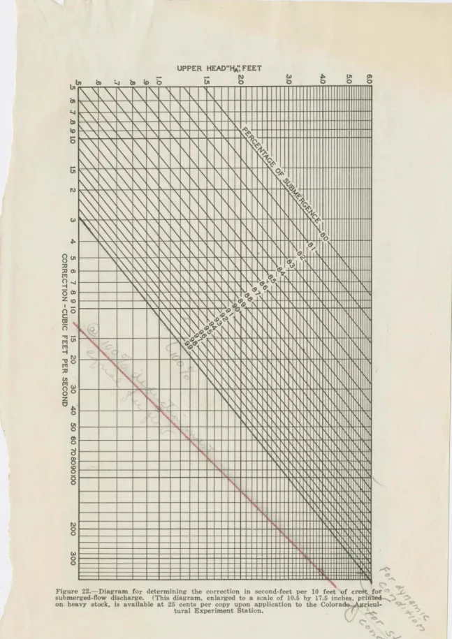
Figure 22.- Diagram for determining the correction in second-feet per 10 feet of crest for submerged-flow discharge. (This diagram, enlarged to a scale of 10.5 by 17.5 inche~. printed-on heavy stock, is available at 25 cents per copy upprinted-on applicatiprinted-on to the Colorade
Agricul-tural Experiment Station. -"<
46 COLORADO EXPERIMENT STATION Bulletin 386
distance between the lines 94 and 95. Vertically below this point,
a correction of 56 second-feet is indicated. From Table V, the free-flow discharge thru a 20-foot flume with an upper head, H1A,
of 3.25 feet is found to be approximately 503 second-feet. The submerged flow, then, is 503- 2 X 56, or 391 second-feet. The correction is determined in the same manner for submerged flow thru other sizes of flumes. For a 10-foot flume, the correction is as shown by the diagram; for the 12-foot flume the correction as
indicated by the diagram is to be multiplied by 1.2 before sub-tracting from the free-flow rate of discharge.
LOSS OF HEAD THRU FLUME
In the design and setting of the large flumes, it is frequently
necessary to know, within reasonable limits, the total loss of head thru the structure. It not infrequently happens that it is
quite important to predetermine the high-water line in the chan-nel upstream from the flume before installation. The diagram shown in Figure 23 will be found useful in making the final
selec-/ I I I v iL (.(.~ v v v v .~o"'Q~ v iL .,~Y ?' ,eoo v v v 0~~~~ /
;=
~~~~~ L ,-zP~ ... v v v ~~d'/. fa~ / / v v .... ~ t-<> eo / ,v v '1oo --i:)/ ~0 v v v v .pO ~o.,."~"'-· .,o v v v v ~0 .... ~~· v v v ~0 v / / ~ y / I / v v v v v vv 1?~0 / / ,.,o v 1/ y v v v I y / v ,., y / / 'I ,.,o v v v v v /y ,o V / ,oo v v v v / v / v v vv v v / / ,., / I""
v v ,-v v v v v v ,o ~0 / v v v v v v v vv v v v v / v v v v ~o· v v v v vv v v 1/ v v v vv '/..0 v vv v ,., v v 1/ vv f-'" v v / v \ V /IV v II / / /1/ v vv 1/ 95 90 65 80 .06 fJ7 .D609QI .IS 20 .25 .30 .35 ~0 .so .so Jo .ao .90 w 12 lA 1.8 1.8 P<"RC[NTAGE Of SUBMERGENCE LOSS Of HEAD IN fEETFigure 28. -Diagram for determining the total loss of head thru large Parshall Measuring
UNITED ·STATES DEPARTMENT OF AGRICULTURE
BUREAU OF AGRICULTURAL ENGINEERING
DIVISION OF IRRIGATION
222 POST OFFICE BUILOINQ
BERKELEY, CALIF.
MAIL ADDRESS: p, 0. BoX 180
August 9, 1932
Mr. Ro Lo Parshall,
Colo. Agr'l Exp. Station, Fort Collins, Colorado
Dear Mr. Pars hall:
Replying to your letter regarding the Fort Lyon
Canal, which was received this morning. I believe you will find the answer to your problem in the material sent you
with a memorandum by Mr. Scobey on August 3rdo In other words, the recovery of head with a large degree of submergence may be greater than the head registered by the upper stilling wello As we approach complete submergence the energy or velocity of the water becomes more nearly zero, and when this velocity is zero then the two wells would register identically t:te same.
However, the recovery of head in the lower section, which is the larger section, and with less velocity, may
represent an apparent piling up of the water. As we approach the condition for hich your table is prepared, this could not be. For the further condition as described by Mr. Scobey, it would and undoubtedly does prevail, and the apparent greater reading in the lower ell is in harmony with hydraulic principles, if our analysis of the problam is correct.
Very truly yours,
Divis ion of Irriga ti on,
Dear Ralph; Aug.l2,1932. Berkeley
Mac showed me your last letter about the Flumes; I note you found more than 100 per cent submergence just as I had suggested possible in my last memo to Mac. Am surprised you had not run into it before. Your
area is materially larger at the Hb point than at the H
8 point for certain
depths of flow and hence there is a great difference in velocities and so a real difference in velocity-heads. A good recovery of velocity head would often throw the Hb gage above the Ha gage for the d~namic condition but it would alwys be just level with the H gage for a static condition and hence
a