IN
DEGREE PROJECT ELECTRONICS AND COMPUTER ENGINEERING,
FIRST CYCLE, 15 CREDITS , STOCKHOLM SWEDEN 2016
Power Enhancement in
Piezoelectric Energy
Harvesting
ZOHREH ALAEI
KTH ROYAL INSTITUTE OF TECHNOLOGY
2
Table of Contents
ABSTRACT ... 4
METHOD ... 6
1 INTRODUCTION: ... 8
2 PIEZOELECTRICITY AND THEIR PERFORMANCE IN ENERGY HARVESTERS ... 12
2.1 INTRODUCTION TO PIEZOELECTRIC EFFECT: ... 12
2.1.1 HISTORY ... 12
2.1.2 PIEZOELECTRIC TRANSDUCTION PRINCIPLE ... 13
2.2 PIEZOELECTRIC CONSTANTS AND CONSTITUTIVE EQUATIONS ... 14
2.2.1 PIEZOELECTRIC CHARGE CONSTANT ... 15
2.2.2 PIEZOELECTRIC VOLTAGE CONSTANT ... 16
3 PIEZOELECTRIC MATERIAL ... 18
3.1 PIEZOELECTRIC CERAMICS ... 18
3.2 PIEZOELECTRIC POLYMERS ... 19
3.3 PIEZOELECTRIC SINGLE CRYSTALS ... 21
3.4 CONCLUSION ... 22
4 CONFIGURATION OF ENERGY HARVESTING SYSTEMS ... 25
4.1 ENERGY HARVESTING SYSTEMS ... 25
4.2 CANTILEVER BEAMS ... 26
4.3 CYMBAL TYPE ... 30
4.4 CIRCULAR DIAPHRAGMS ... 31
4.5 CONCLUSION ... 33
5 PIEZOELECTRIC CIRCUIT TOPOLOGIES ... 34
5.1 MECHANICAL AND ELECTRICAL MODELING ... 34
5.2 SYNCHRONIZED SWITCH HARVESTING TECHNIQUES ... 40
5.3 SYNCHRONOUS ELECTRIC CHARGE EXTRACTION ... 42
5.4 VOLTAGE DOUBLER ... 43
5.5 CONCLUSION ... 44
6 EXPERIMENTAL RESULTS... 47
7 USE OF PIEZOELECTRIC ENERGY HARVESTING IN MEDICAL ENGINEERING: 50 8 CONCLUSION ... 53
4
Abstract
Piezoelectric energy harvesting has been around for almost a decade to generate power from the ambient vibrations. Although the generated power is very small, but there are several ways to increase and enhance the generated power. This project presents different methods of optimizing the output power by changing the structural configuration of the energy harvesters, selection of piezoelectric material and circuit interface of these harvesters. To understand the different steps of the enhancement, the process of energy conversion by piezoelectric material has been first looked at. Different groups of piezoelectric material were studied to see what kind of materials have the ability of increasing the generated power. As mechanical configuration of the energy harvesters has a significant effect on the output voltage, their configuration such as Cantilever beam type, Cymbal type and Circular diaphragms has been described and compared. After the power generated in the piezoelectric crystal , the current is sent to through an interface circuit to get rectified and regulated. This circuit can be modified to increase the power as well. There are several types of circuits that can increase the output voltage significantly. Synchronized Switch Harvesting (SSH) techniques, Synchronous Electric Charge Extraction technique and voltage doubler are such examples. These techniques have been also studied and compared.
Because of the outgrowing industry of piezoelectric energy harvesting in Medical field, their function and their progress has also been reviewed.
6
Methods
Increasing the output voltage of piezoelectric energy harvesters are one of the most important aspects in this field. This is because of their low range of generated power which has to be increased if it is desired to be used in the industry. For this reason, this work has been based to find different solutions that lead the piezoelectric energy harvesters to experience a boost of power. During the research, it was noticed that there are three important facts that can lead to such a boost and based on those, the work of this study was directed to a certain direction for finding advantages and disadvantages of different methods for power enhancement in piezoelectric energy harvesting. These facts include harvester’s mechanical configuration which is about how piezoelectric crystals can be used in a mechanical system so the stress can be applied easier for a maximum power. In this matter, three different configurations were studied and compared to see which model is most likely to generate a desirable amount of power. The second method affecting the output voltages is the right choice of material. In this part, piezoelectric material was divided in to three different groups and each was studied and compared to each other. Furthermore, to investigate how the output power can be enhanced, electrical circuits that transfer the generated power from the piezoelectric material to a storage buffer was studied. Different circuit topologies used nowadays in this field, were chosen and compared to see which circuit topology can enhance the power.
An experimental work was also conducted to see how vibration and deflection can affect the generated and a simple circuit with a piezoelectric power source was connected to a LED to experiment if the piezo material can light up the LED. Last but not at least, the application of piezoelectric energy harvesting in the medical field was reviewed to see whether if this kind of technology has a bright future in the medicine.
8
1
Introduction
Energy harvesting or energy scavenging is a process of generating electricity from ambient environment through various sources of energy. The development of energy harvesting from natural sources has received a great deal of interest in the industrial world and research communities over the past few decades. Nowadays electronic devices use wireless data transmission to function. A lot of devices are desired to be wireless and self-powered to make everyday life easier and also to use natural ambient sources to have a green world and clean from fuel based energy. Supplying power for these devices may proceed from batteries or some other wireless power or energy suppliers. But energy suppliers or batteries have some disadvantages such as replacement, discharging and other maintenance costs. For example, in many areas that devices are controlled by remotes, continuous charging methods aren’t possible. So some methods must be used to keep the batteries charged. To resolve such problem, we need to work on different ideas to provide the required energy. Energy harvesting can be the most efficient way to provide the energy from the ambient environment. It can help to utilize the energy for future use. Energy harvesting hierarchy can be categorized as shown in figure 1. As it can be seen in the picture there are several ways to extract energy from ambient sources. Among them motion is one of sources which includes piezoelectric material as one of the ways to generated power.
9
Figure 1. Hierarchy of main energy harvesting technologies. (Adapted from[1]) The vibration (motion) based energy harvesting is most prominent way to generate electricity from the environment. Because generating the vibration or using the natural vibration is almost easy to achieve. The three mechanisms that can convert vibration energy into electricity are electromagnetic, electrostatic and piezoelectric transductions. Piezoelectric transduction is the most effective technique compared to other two transductions mechanisms because piezoelectric materials offer higher power densities and ease of applications. Also they are more sensible and advisable for micro electro mechanical systems (MEMS) implementation. Advantages of using piezoelectric materials in energy harvesting are ease of application, high power density, no requirement of input voltage and relatively mature fabrication techniques at micro- and macro-scales[1]. As it is clear in the following picture which shows the power density of different materials how vs. voltage, piezoelectric material has the most power density in comparison to other materials. This difference in the power density makes the piezoelectric material superior to the other materials for a desired power.
10
Figure2. Power density vs. voltage of different materials. [Adapted from 2]
Generally, when working with piezoelectric materials, three primary steps are involved: (1) trapping the mechanical stress from the ambient source, (2) converting the mechanical stress into electrical energy and (3) processing and storing the produced power for the later uses. Therefore, in modeling piezoelectric energy harvesters these steps have to be considered. Modeling is an important approach to forecast their function. However, despite the fact that the power density of the
piezoelectric material is larger than the other materials, still the generated power is in micro scale. Thus, for using such materials in self powered devices their output power has to be enhanced. There are different ways to enhance the output power. Using different piezoelectric materials, piezoelectric mechanical configuration and the electrical circuit will enhance the power and enable us for a better self powered and wireless systems. In this paper we will look at how these approaches can increase the output power. The following figure shows the main three steps in the energy
11
12
2
Piezoelectricity and Their Performance in
Energy Harvesters
2.1 Introduction to Piezoelectric Effect:
2.1.1 History
The word ‘‘piezoelectricity’’ is derived from the Greek word ‘‘piezein’’, which means to ‘‘squeeze’’ or ‘‘press’’.[4] This special family of material exhibits an interesting effect known as piezoelectric effect, which will produce electricity when it’s deformed under a stretch or stress.
The first experimental demonstration of the piezoelectric effect was published in 1880 by the brothers Pierre Curie and Jacques Curie. They combined their knowledge of pyroelectricity with their understanding of the underlying crystal structures that gave rise to pyroelectricity to predict crystal behavior, and demonstrated the effect of using crystals of tourmaline, quartz, Topaz, cane sugar, and Rochelle salt. The Curie
brothers discovered that when a mechanical stress such as pressure or vibration applies on these crystals, electricity generates and the voltage of these electrical charges is proportional to the applied stress. Beside that they also realized that not only their chosen material shows piezoelectric phenomenon, but also the crystalline orientation of those material was crucial in creating the condition for the electricity to be generated from mechanical application to the material. The first serious application on piezoelectric devices began during World War I by Langevin and French co-workers to perfect an ultrasonic submarine detector. Later in the Second World War U.S., Japan and the Soviet Union, started their work to manufacture piezoelectric
13
ceramics with astonishing performance and developing piezoelectric devices. In the last two decades, the growth of piezoelectric material has been increasingly apparent in the use of the energy harvesters, sensors and actuators and a mass of researches have been dedicated to this field of work.
2.1.2 Piezoelectric Transduction Principle
The general theory of piezoelectricity is the coupling of mechanical and electrical energy in special class of ceramics and crystals. When the piezoelectric materials face a mechanical strain generated from a stress, they can convert this stress into electric current or voltage. The basic effect is closely related to electric dipole moments in solids where they show a local charge separation. This mechanism takes place based on the fundamental structure of a crystal lattice where polarization is induced and an electric field is established across the piezoelectric crystal when it is mechanically stressed. Piezoelectric materials generally have a charge balance where negative and positive charges are separated, but symmetrically disturbed so overall charge is electrically neutral. When an external force, such as, applying physical stress is applied, this charge balance disrupts and the internal structure gets deformed. Consequently the charges gets separated and the neutrality gets disrupted, creating a surface charge density, which can be collected via electrodes. [3]
Figure 4: disruption of the neutral charge. [Adapted from 4]
Piezoelectricity depends on the orientation of dipole density, crystal symmetry and the applied mechanical stress. In monocrystals, the polar axes of all of the dipoles are
14
aligned in one direction. They demonstrate symmetry even if the crystal is cut into pieces. However, in polycrystalline there are different regions within the material that have a different polar axis and there is no net polarization within the crystal. This difference has been shown in the following figure. (Figure 5)
Figure 5: Orientation of poles in monocrystalline and polycrystalline. (Adapted from [1])
Figure 6: process of polarization and the polarization surviving. (Adapted from [1])
In order to achieve the piezoelectric effect in polycrystalline, the sample is heated to the Curie point for the molecules to move freely. Along the heat a strong electric field is applied on the sample to force all of the dipoles in the crystal to line up in one direction. When the electric field is removed, most of the dipoles are locked into a same configuration and attains permanent net polarization. (Figure 6)
2.2 Piezoelectric Constants and Constitutive Equations
Piezoelectric crystal and ceramics are anisotropic materials, which means their properties are directionally dependent. Generally, each constant has two subscripts
15
that indicates the direction of the two related quantities, such as stress (force on the ceramic element / surface area of the element) and strain (change in length of element / original length of element) for elasticity. Direction X, Y, or Z is represented by the subscript 1, 2, or 3, respectively, and shear about one of these axes is represented by the subscript 4, 5, or 6, respectively.To model a piezoelectric device, we have to consider the fact which direction, the stress has to be applied for an optimal strain. Also in choosing material, the value of the constants has to be known for an optimal effect from the harvesting system.
Figure 7: Direction of forces affecting the piezoelectric material
2.2.1 Piezoelectric charge constant
Piezoelectric charge constant is defined as the electric polarization generated in a material per unit mechanical stress applied to it. The first subscript refers to the direction of polarization generated in the material (at E = 0) or to the applied field strength; the second refers respectively to the direction of the applied stress or to the direction of the induced strain. The non-zero piezoelectric constants are:
d33: Induced polarization in direction 3 (parallel to direction in which ceramic element
is polarized) per unit stress applied in direction 3
d31: Induced polarization in direction 3 (parallel to direction in which ceramic element
is polarized) per unit stress applied in direction 1 (perpendicular to direction in which ceramic element is polarized)
16
d15: Induced polarization in direction 1 (perpendicular to direction in which ceramic
element is polarized) per unit shear stress applied about direction 2 (direction 2 perpendicular to direction in which ceramic element is polarized)
2.2.2 Piezoelectric Voltage Constant
The piezoelectric voltage constant (g) is the electric field achieved by a piezoelectric ceramic per unit of mechanical stress applied or alternatively, is the mechanical strain experienced by a piezoelectric material per unit of electric displacement applied. The first subscript to (g) shows the direction of the electric field generated in the material, or the direction of the applied electric displacement. The second subscript is the direction of the applied stress or the induced strain, respectively. (g) is an important constant in piezoelectric theory for determining a material's suitability for sensor applications.
g33 : Induced electric field in direction 3 (parallel to direction in which ceramic
element is polarized) per unit stress applied in direction 3.
g31 : Induced electric field in direction 3 (parallel to direction in which ceramic
element is polarized) per unit stress applied in direction 1 (perpendicular to direction in which ceramic element is polarized)
g15 : Induced electric field in direction 1 (perpendicular to direction in which ceramic
element is polarized) per unit shear stress applied about direction 2 (direction 2 perpendicular to direction in which ceramic element is polarized).
The constitutive equations for linear piezoelectric materials under low stress (X) are written according to the following formulas, these equations define how the
piezoelectric material’s stress, strain, charge density displacement and electric field interact:
𝑥 = 𝑠𝑋 + 𝑑𝐸 𝐷 = 𝜀𝑋 + 𝑑𝑋
17
Where 𝑥 is the strain, 𝑠 the elastic compliance, E the electric field, D the dielectric displacement, 𝜀 permittivity. The highlighted part of the equations applies for all the materials which strain is in relation with elastic compliance and stress. And for
dielectric materials also, the dielectric displacement is in relation to stress. The second part of the equations containing piezoelectric charge constant (d) they are only
properties of piezoelectric material. These equations are important when it comes to making piezoelectric material.
18
3
Piezoelectric Material
As it was mentioned before piezoelectric materials are a group of element that can generate electricity when they are under mechanical deformation. There are over 200 piezoelectric materials made with combination of different materials. Because of their different piezoelectric constants, they generate different voltages. Therefore, selecting the most appropriate material for the energy harvester is important. Piezoelectric material can be divided into three different groups: Piezoelectric ceramics,
piezoelectric polymers and piezoelectric single crystals. Generally piezoelectric single crystals and ceramics present better piezoelectric properties, but they are also rigid and brittle toward high stresses, which makes them unsuitable for some of the energy harvesting application.
3.1 Piezoelectric Ceramics
Piezoelectric ceramics are one of the most known materials in the field of the piezoelectricity and energy harvesting. The low cost, easier incorporation and better piezoelectric properties compared to the other piezoelectric material has made them a better choice in the energy harvesting devices. Barium titanate (BaTiO3) was the first
piezoelectric ceramic that was discovered in laboratory; but later lead zirconate titanate, known as PZT ceramic became the most popular and common ceramic in the application of piezoelectric energy harvesting. Other alternatives are also receiving some attention where efficiency and temperature performance is not the first consideration but other factors such as flexibility, light weight and toxicity play an important and crucial role. For example, sodium potassium niobate displays properties very identical to PZT without the lead existence.
19
PZT is important because of its high Curie temperature that allows it to operate in a wide range before it loses the piezoelectricity effect. In the past few years a wide range of this material has been modified by changing their chemical composition such as PZT-5H and PZT5-A.
Piezoelectric ceramics are chosen based on the characteristics of the mechanical energy applied to them. One of the advantages for piezo ceramics is their easy
integration to thin sheets can simply be planted on a cantilever beam structure, which this mechanical structure is one of the most used structure in energy harvesters. Roundy[5] did a study using a PZT-5A ceramic on a cantilever beam with a length of 1,75 cm while a proof mass was attached to the tip of the cantilever to decrease its resonance frequency. The device was set at 100 Hz and, matching its natural frequency and a driving acceleration of 2.25 m/s2. By setting the load resistance to about 220 ohms , he achieved a power around 60 𝜇𝑊. Later he experienced with two additional lengths of 1.5 cm and 3 cm and was able to achieve an output power of 200 𝜇𝑊 and 380 𝜇𝑊, respectively. Yuan et al [6] also studied the output power of
trapezoidal and rectangular PZT cantilevers, which were a few centimeters larger than
what Roundy used in his investigation. Without a proof mass he was able to obtain 24.2 mW from trapezoidal PZT and 8.6 mW from rectangular PZT as output power. one of the advantages of PZT ceramics is that their properties can be improved by changing the ratio of zinconate titanate. Also complete insensitiveness to humidity and to atmosphere change, this material is considered a favorable material.
3.2 Piezoelectric polymers
Piezoelectric polymers can be categorized into three different groups. Bulk polymers, composite polymers and voided charged polymers. Bulk polymers are solid polymer films and they have the piezoelectric effect due to their structural orientation. This group of polymer can be divided into two groups, which they are the semi-crystalline polymers and amorphous polymers. For bulk polymers there are two main obligations that must be fulfilled for the material to be able to have the piezoelectric effect. Primarily, the molecular structure of the polymer should naturally contain molecular dipoles. Second, these dipoles can be reoriented within the bulk material and kept in
20
their preferred orientation state. PVDF (polyvinylidene difluoride ) as a semi-crystalline polymer is one of the extreme cases of the high-energy density material among piezoelectric polymers. It contains about 50% crystals that are embedded in an amorphous matrix. Beside their high-energy density, they are easy to deform under the mechanical shock, which makes them resilient and suitable for curved surfaces. In amorphous polymers the polarization is not in a state of thermal equilibrium, but rather a quasi-stable state due to the freezing of molecular dipoles. The result is a piezoelectric-like effect. [7] In amorphous material, piezoelectricity is the result of orientation polarization of molecular dipoles. Examples of such polymers include polyimide and polyvinylidene chloride (PVDC)
Composite polymers are a group of polymer material with embedded inorganic piezoelectric material. One of the importance of combining piezoelectric ceramics with polymers is to achieve the advantages of both materials, which includes the higher coupling factor and dielectric constant from ceramics and the mechanical flexibility from polymers. These types of composite polymers are preferable for acoustic devices because of the polymer’s low acoustic impedance and fewer spurious modes.[8]
The third group of piezoelectric polymers is voided charged polymers. This structure was first invented by Gerhard Sessler in the early 1960s and its sometimes called cellular polymers. Voided charged polymers are polymer materials that contain internal gas voids. When the surface of the polymer, surrounding the voids are charged which can add extra voltage to the generated voltage. Such structures can have a high piezoelectric coefficient d33 which can reach up to 20 000 pC N−1 in some cases. [9] However, the piezoelectric coefficient in such materials rely on factors that are distinct from the regular piezoelectric materials. Factors related to voids can have crucial effects in the value of piezoelectric constant. Also density and shape of the voids can also affect the distribution of the final dipoles which is not desirable in the harvesting system. Pressure of gas inside the voids can also affects the amount of ionization occurring during the poling process.As mentioned before the importance of the piezoelectric material is that changing the material and producing new elements can help to boost the voltage. According to a study by
21
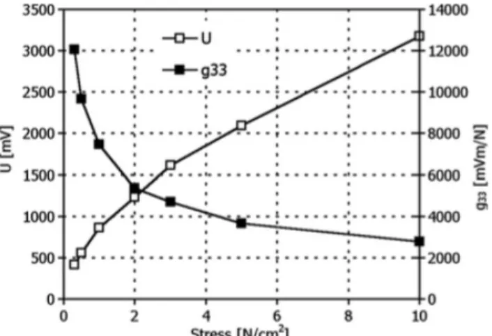
Klimiec et al.[10], the voltage of a new developed piezoelectric polymer called polypropylene–polyethylene (PE–PP) was conducted. This polymer was able to reach a voltage three time more in comparison to PVDF material and also exhibited a high sensitivity while giving an instant voltage response when stress is applying to it. The following graph was achieved during this study showing how the voltage of this material responds an increasing stress.
Figure 8: Piezoelectric voltage (measured values) and the g33 value (calculated) as a function of mechanical stress applied to the test PE–PP 11 lm thick foil. Measuring
electrode surface area 10 cm2. (Adapted from [11])
3.3 Piezoelectric Single Crystals
As the name of this group of material suggests, piezoelectric single crystals are counterparts of piezoelectric ceramics. Ferroelectric single crystals such as lead-nickel niobate [Pb(Ni1/3Nb2/3)O3 or PNN], and lead-titanate [PbTiO3] are two most
popular and widely used materials based on their performance in piezoelectric energy harvesting. In these materials, the arrangement of the positive and negative ions are highly ordered, causing an alignment of the dipoles across the entire material which makes them having a higher piezoelectric strain constant than ceramics. For small size devices, ferroelectric single crystals are favorable, because they have higher Young’s moduli than the ceramics which results for the material to have a lower resonance frequency. Bade et al. has done a great job comparing the performance of the PMN single crystal with a ceramic using unimorph cantilever beam configuration. In this
22
experiment a piezoelectric element in the size of 10×7×1 𝑚𝑚2 with the resonance frequency of 900 Hz. The output power of this structure was 4 mW whereas for the ceramic material, only 0.2 mW was obtained. [11]
Albeit the high output power of piezoelectric single crystalline, the manufacturing cost of such material is greatly higher than ceramics, making them less suitable for low cost products. Adding to disadvantages of single crystals, their frangibility also must be mentioned because these materials are brittle in comparison to
polycrystalline, which is due to their lack of ceramic grain boundaries. [12] Also compared to their polycrystalline counterparts, single crystal materials also more easily lose piezoelectric properties when exposed to high electric fields that are opposite to their poling directions. [13]
3.4 Conclusion
As we have explained so far the output power of the piezoelectric energy harvesters can be manipulated by changing and combining the materials to increase the
generated voltage. For example, by increasing the piezoelectric voltage constant, the generated voltage can also be increased. However, considering other facts such as resonance frequency of the piezoelectric element, mechanical and piezoelectric properties, design and size of the piezoelectric elements, the voltage can vary from micro to milliwatts. To design an efficient energy harvester, the application has to be known to choose a proper material. For example, in application of radio transmitters, to provide an energy of a radio wireless transmitter to transmit every 165 s, an output of 50 µW under a moderate condition is enough in comparison to increasing the frequency and strain to generate 150 mW from a piezoelectric material known as PFC which is a ceramic polymer composites. [15] Generally, piezoelectric polymers can be manufactured as thin sheets and can be cut or stamped into nearly any shape desired for a special application and they also show a high mechanical strength and resistance. They have better sensing ability based on their higher piezoelectric voltage constant compared to ceramics.
23
The following table shows some reported piezoelectric energy harvesters with
different sizes and frequency resonances which some of them we reported. As we can see how the peak power changes with different sizes, shapes and applied frequency in different materials.
Table 1: Some piezoelectric energy harvesters with their performance.
All the points, advantages and disadvantages of different piezoelectric material that was mentioned in above can be summarized n the following observations:
1) Albeit ceramics among are brittle toward large amount on strain among
piezoelectric materials, still their high output power compared to other materials makes them special in piezoelectric devices.
2) Though having a disadvantage of the smallest output power, piezoelectric polymers are the most flexible with the smallest coupling factor among piezoelectric materials.
24
or higher. [13] For achieving a lower frequency one of the two conditions must be fulfilled. A long PZT element or a large excitation is needed for obtaining milliwatt output power.
4) Flexibility helps the piezoelectric materials to operate at low input frequencies or at large amplitude of excitation. The reason behind this is the speed of operation in the system. (i.e. piezoelectric polymers)
5) Despite the high density of single crystals compared to the other piezoelectric materials, their high cost of manufacture plays a crucial in their limited use in energy harvesting devices.
25
4
Configuration of Piezoelectric Energy Harvesters
4.1 Energy harvesting systems
Modeling a piezoelectric energy harvester is important. Mechanical configuration of the harvesting system can also boost the output power. Therefore, tremendous efforts have been put into developing different models of energy harvesters. Modeling a piezoelectric harvester includes modeling the mechanical configuration of the
harvesters which is a structure that the piezoelectric element is mounted on to be able to vibrate. Also the modes of piezoelectric material which is the direction of the mechanical stress applied on the element is part of the mechanical structure of the piezoelectric energy harvesters.
Generally, in piezoelectric materials, there are two primary modes: longitudinal mode (3-3 mode) or transverse mode (3-1 mode) with a corresponding resonant frequency. In the longitudinal mode, the direction of the mechanical stress, T, is parallel to the electric or polarization direction, P, with a corresponding resonant frequency and in the transverse mode, the direction of the mechanical stress, T, is perpendicular to the electric or polarization direction, P, with a corresponding resonant frequency. In other word when a voltage is applied to the piezoelectric element in transverse mode, it compresses in the direction of the z-axis and the voltage is positive while in the transverse mode the stress compresses along the x-axis and the voltage is negative.
Figure 9: Longitudinal piezoelectric mode (Adapted from [15])
26
Figure 10: Transverse piezoelectric mode (Adapted from [15])
Studies of mechanical to electrical energy in piezoelectric energy harvesting has shown that the the longitudinal mode (33) is 3-5 times show better generation of power than the transverse mode (3-1 mode). In this mode the electrical charge is also twice the transverse mode with the same shape and size. However, the downside to the longitudinal mode is the hard fabrication and also its too stiff to couple
mechanical energy into its structure.[15] Beside the fact that the voltage coefficient of the 33 mode is larger than 31 mode, which causes higher output energy, but also the gap between the electrodes which is large affects the output energy. In this mode however the limiting factor is the length of the piezoelectric material. In total based on the different properties, the transverse mode appears to show the best performance but the complex fabrication and high costs makes the longitudinal mode, more
favorable. There are mainly three different mechanical structure used in piezoelectric energy harvesting that the piezoelectric material is implemented in it to vibrate. They are cantilever beam type, Cymbal type and circular diaphragms. The vast majority of piezoelectric energy harvesting devices use cantilever beam with one piezoceramic layer (unimorph) or two piezoceramic layers (bimorph).
4.2 Cantilever beams
A cantilever beam energy harvester has a very simple structure and can produce a large deformation under vibration. Most of energy harvesting devices operate with cantilever beam structure because it can work in both d33 and d31 modes. This device
27
is a beam that is supported by only one end and it is laminated with a PZT layer, sandwiched between upper and lower electrodes, which can produce a large
deformation and is often referred to as a “fixed-free” beam. These two piezoelectric layers are called bimorph but when only one layer is used, its called unimorph cantilever beam. When vibrations are applied to the generator in the longitude direction, the support structure will move up and down in sync with the external acceleration. The vibration of the beam is induced by its own inertia; since the beam is not perfectly rigid, it tends to deflect when the base support is moving up and down. [14] Commonly, a proof mass is added to tip of the beam to increase or control the amount of deflection which causes a decrease in the resonant frequency of the beam and an increase in the deflection of the beam as it vibrates. So by definition the deflection and stress have a direct relationship; larger deflection causes more stress, strain and consequently a boost in the output voltage and power. The principle behind connecting electrodes to the cantilever beam is to conduct the electric charges
produced to an electric circuit, where they can be exploited to charge a capacitor or a load. A cantilever beam can have many different modes of vibration, each with a different resonant frequency. The first mode of vibration has the lowest resonant frequency, and typically provides the most deflection and therefore electrical energy. However, a lower resonant frequency is needed because its closer in frequency to physical vibration sources and generally more power is produced at lower
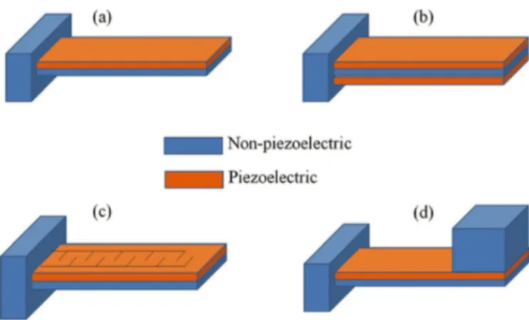
frequencies. [15] Therefore, energy harvesters are generally designed to operate in the first resonant mode. The following figure shows unimorph and bimorph cantilever beam and a cantilever beam with a tip mass.
28
Figure 11: Various configurations of piezoelectric cantilevers: (a) unimorph; (b) bimorph; (c) a piezoelectric cantilever with interdigitated electrodes; (d) a piezoelectric cantilever with proof mass at its free end. (Adapted from [15])
To enhance the output energy in 33 mode for higher energy output in cantilever beams, an interdigitate electrode design can be used. In this method an array of positive and negative electrodes that are fabricated narrow are mounted on the piezoelectric element. Under piezoelectric material poling, the electrodes cause the piezoelectric element to be polarized in the lateral direction in comparison to the normal polarization which is vertical direction. By doing this process the direction of the stress is parallel to polarization direction when the piezoelectric element is under a stress. This method was previously mentioned as the the longitudinal mode.
In cantilever beams the replacement and shape of the piezoelectric element can utilize the generated voltage. The strain is at maximum in the clamped end of the cantilever and when the piezoelectric element goes further away from the clamped end, the voltage decreases. Thus, not the entire length of the piezoelectric element is involved in power generation. Also the material of the beam can affect the energy conversion. A comparison of the output power generated for a variety of materials used as a substrate is shown in Figure 12.
The results are based on a fixed-geometry cantilever beam with equal PZT and substrate layer thicknesses. [16] As its seen aluminum can produce more power compared to other metals.
29
Figure 12: Comparison of power generation for materials of the substrate (Adapted from [16])
The power generated in cantilever beams not only depends on the location of the piezoelectric element and its shape (which it was mentioned before) but it also depends on the location of the applied force. According to a study by A.T. Mineto et
al [17], a beam with length, width, thickness of 0.5, 0.05, and 0.04 respectively with a
piezoelectric material with length, width, and thickness is 0.05, 0.05,0.5x10-3 m
respectively, mounted on it was exposed to force equal to 1 N. The force was applied on different placed of the beam. The following results shows how output energy can vary with the location of the applied force and location of the piezoelectric material (PZT).
Figure 13: (a) Power versus location of the applied force (b)power versus position of the piezoelectric material mounted on the cantilever beam. (Adapted from [17])
30
As its shown in the graphs, the maximum power 2.6 mw was obtained at location of 0.5 m which is the free end of the beam. This power is the optimal power in this design with 1N force and with first natural frequency of 13.4 Hz. Also the location of piezoelectric material is important. The largest strain occurs at the clamped edge of the cantilever beam.
4.3 Cymbal type
In addition to cantilever beam energy harvesters, Cymbal energy harvesters have been developed for applications with high impact forces. Typically, these types of energy harvesters consist of two electric metallic discs and a hollow metal end cap in each side of the discs. The presence of cavities allows the metal end-caps to act as as a mechanical transformer to transform the radial displacement of piezoelectric ceramic into longitudinal displacement and amplifying it and thus both d33 and d31
piezoelectric charge coefficients are involved to contribute to the charge generation of the energy harvester and a much higher displacement S can be produced on the
cymbal type. The primary factor for energy harvesting transduction is governed by the effective piezoelectric field constant deff and piezoelectric voltage constant geff. Therefore, to enhance the power output the multiplication of these factors had to be increased and also the design should be in a way that the energy harvester can bear high cyclic stresses without any fracture. Regarding the high transduction rate in the cymbal type, this type offers higher transduction rate in comparison to bimorph cantilever beam because the piezoelectric of the cymbal gets amplified by the structure. This is because of the design. In this design the metal caps are commonly made of steel based on their high strength in comparison to aluminum and brass. the amplification factor in cymbal harvesters can vary between 10-100 times
depending on the design of the energy harvester. The relation between amplification and effective piezoelectric field constant is:
𝑑344 = 𝑑
31
where A is the amplification factor of the harvester. The subtraction sign is due to the negative value of 𝑑27. The following figure shows the design of the Cymbal energy harvester.
Figure 14: Cymbal piezoelectric energy harvester in 3D and Cross sectional (Adapted from [18])
There are several disadvantages in cantilever beam configuration over cymbal in transferring the stress more efficiently. Also the maximum displacement of the cantilever beam is limited based on the maximum force applied to the beam and therefore the voltage generated is also limited and less compared to the cymbal type. Bending also causes the piezoelectric element to get weaker over time and hence shortening its lifetime. [19] Cantilever beams develop cracks under high stress forces. However, the most important disadvantage of the cymbal type in spite of their ability to generate high voltage, is their low sensitivity to ambient sources due to their low vibrations. Studies have shown that a cymbal transducer with a piezoelectric ceramic with 29 mm diameter and 1mm thickness can generate 39mW and 52mW when a force of 7.8 and 70 N has been applied on them at frequency of 100 Hz.[20] Another disadvantage to mentions is the tendency of the end caps to change their geometric shape in terms of dimension in many applications where high efficiency was required. Also fabricating end caps with perfect symmetry under epoxy layer may make some irregularities such as double frequency. [21]
4.4 Circular Diaphragms
Piezoelectric circular diaphragms are very similar to cantilever beams configuration. To be able to stablish a piezoelectric circular diaphragm, a thins circular disk of the piezoelectric crystal is manufactured and then its bonded to to a metal shim and then
32
clamped to an edge so the vibration of the edge can supply the required vibration for the piezoelectric material to get excited. Like cantilever beams a proof mass can be attached to the center of the circular diaphragms to provide a prestress to the
piezoelectric material. Like piezoelectric cantilever beams, circular diaphragms also operate best in the in the 31 mode. The following figure shows the configuration of a circular diaphragm type.
Figure 15: Schematic diagram of PZT circular diaphragm harvester.
A study done by Chen and Yang has proved that the piezoelectric circular diaphragms with a prestress of 1.2 N at 113 Hz can generate power up to 12mW across a 33 k ohm resistor. [22] This amount of power can be used in some MEMS and wireless sensors. According to this study the output power can be raised by increasing the quality of mass which leads to that the output power can be enhanced by changing the contact part between the mass and the piezoelectric disc affect the output power. This study has changes the maximum power by 2 mW compared the the previous
limitation where the maximum output power was between 2 to 10 mW. To increase the output power, multiple circular diaphragms in series can also be connected to enhance the power further more. However, the number of the harvesters connected to one another are not linear with the output power. The thickness of the piezoelectric material can also affect the output power like piezoelectric material. What cantilever beam and cymbal type configurations share, is their ability to bend but with
increasing thickness in the piezoelectric crystal, the resistance for bending will increases as well which will result in less deflection. This will consequently
33
lead to low power conversion. For optimum power the thickness should be in an agreement with the piezoelectric deflection.
4.5 Conclusion
In this section configuration of different piezoelectric material was studied to see how energy harvesting can be enhanced. Cantilever beam is one of the configurations among others that has more promising features. Among these features, resonance at first natural frequency are one of the reasons that make difference in energy
harvesting systems. According to studies, piezoelectric material attached to a
vibrating structures produce maximum electrical power when they are excited at their first natural frequency where they experience the largest deflection. [23] Cantilever beam are one of the models that can easily produce a large power when they are resonated on their first natural frequency. This can also be done by attaching a mass to the tip of the beam so it can deflect the beam at the frequency that it matches the piezoelectric material. Despite the result showing that the cymbal configuration has produced more power than cantilever beam, it has some disadvantages that can does not make a suitable choice for many aims which makes it more practical in heavy industry than the micro control and wireless systems. Circular diaphragms are also good candidates but studies have shown that in comparison to cantilever beams they are still not much popular and they produce less power compared to them.
34
5
Piezoelectric Circuit Topologies
5.1 Mechanical and electrical modelingIn previous parts, we talked about the general functionality of piezoelectric energy harvesters. These types of harvesters are only useful and liable for today’s high demanded industry if only the output power is increased while keeping their lengths and volumes as small as possible. However, to increase the output power, other ways must be sought. The most promising approach is to design an efficient interface charging circuits, storage buffers and hot structure configuration. In this part, we will provide a review on different approaches and see how the output power can be enhanced efficiently by changing electrical components of the interface circuits. As it was mentioned before, cantilever beams are the most used configurations in
piezoelectric energy harvesters. Their popularity is because they enable relatively high stress levels on the piezoelectric material while reducing the dimensions of the devices. [1] Therefore, in this part all the optimization methods are based on
configuration of cantilever beams.
Because the piezoelectric power generator is excited at a sinusoidal force, where the first natural frequency causes the maximum power generator with small displacement and the movements are linear, it can be modeled mechanically with a rigid mass (M), spring (K), damper (C ) and piezoelectric material. The following figure shows the spring mass model.
35
Figure 16: Mechanical representation of the piezoelectric system
In this mechanical model, the spring and damper represent structure stiffness and mechanical loss of the system respectively. The Force (F) represents the external force applied to the mass and the displacement of the rigid mass is u.
According to Newton’s law the spring mass model can be written as the following: 𝑀𝑢 + 𝐾𝑢 + 𝐶𝑢 = 𝐹=
Where 𝐹= is the the total force and it is equal to: 𝐹= = 𝐹 − 𝛼𝑉
In this expression, 𝛼 is the factor of the piezoelectric element and V is the output voltage. The force factor 𝛼 describes the piezoelectric elements ability to convert mechanical to electrical energy. Inserting them together we will have:
𝑀𝑢 + 𝐾𝑢 + 𝐶𝑢 = 𝐹 − 𝛼𝑉
Multiplying this equation by velocity (𝑢)and then integrating the expression will give: 𝑀𝑢 = 𝐹 − 𝐾𝑢 − 𝐶𝑢 − 𝛼𝑉 𝐹𝑢 𝑑𝑡 = 1 2 𝑀𝑢D+ 1 2𝐾𝑢D+ 𝐶𝑢D 𝑑𝑡 + 𝛼𝑉𝑢 𝑑𝑡
36
The following table represent what kind energy are each term:
Table 2: Definition of the piezoelectric energies from equation From the constitutive equations of piezoelectricity, the current flowing out of the piezoelectric element, I, can be expressed as:
𝐼 = 𝛼𝑢 − 𝐶F𝑉
where Cp is the piezoelectric capacitance. The transferred energy can then be rewritten as:
𝛼𝑉𝑢 𝑑𝑡 = 1
2 𝐶F𝑉D + 𝑉𝐼 𝑑𝑡
where the transferred energy is the sum of the electrostatic energy stored on the piezoelectric element and the energy delivered to the connected load. [24] the second term of the equation above in the right hand side is the harvested energy that has to be enhanced for a better efficiency and output power.
𝐸 = 𝑉𝐼 𝑑𝑡 𝑃 = 1
𝑡 𝑉𝐼 𝑑𝑡
Earlier 𝐶F was introduced as the capacitance of the piezoelectric material. This is because when the piezoelectric material gets excited, the charge gets accumulated in it and then it gets discharged. There are several factor contributing to the magnitude of
Energy Equation Provided 𝐹𝑢 𝑑𝑡 Kinetic 1 2 𝑀𝑢D Potential 1 2𝐾𝑢D Dissipated 𝐶𝑢D 𝑑𝑡 Transferred 𝛼𝑉𝑢 𝑑𝑡
37
the capacitance. These factors are such as permittivity of the material, thickness and area. The magnitude of the capacitance as it mentioned before is:
𝐶H = 𝐴 𝜀 𝑑
The following figure shows the electrical representation of the piezoelectric material. There is also a load connected parallel to the capacitance which shows the loaded piezoelectric output voltage in the frequency domain as a function of R to express the loaded piezoelectric output voltage in the frequency domain as a function of R.
Figure 17: Uncoupled equivalent circuit of the piezoelectric harvester without and with the the resistance load.
The following formulas shows the current and voltage where 𝑉 and 𝑢 present the maximum voltage and maximum displacement.
𝐼 = 𝛼𝑢 − 𝐶F𝑉 𝑉 𝑅 = 𝛼𝑢 − 1 𝑗𝜔𝐶𝑝𝑉 𝑉 = 𝛼𝑅𝑢 − 𝑅 𝑗𝜔𝐶F𝑉 𝛼𝑢 𝑉 = 𝑅 𝑗𝜔𝐶F + 1 𝑉 = 𝛼𝑅 1 + 𝑗𝜔𝑟𝐶F𝑗𝜔𝑢
38 𝑃N = 𝑉D 𝑅 = (𝑉 2)D 𝑅 = 𝑉 𝑉∗ 2𝑅 𝑉∗ = − 𝛼𝑅 1 − 𝑗𝜔𝑟𝐶F𝑗𝜔𝑢 𝑉 𝑉∗ 2𝑅 = 𝜔D𝑢D 𝛼D𝑅D 2𝑅 1 + 𝑗𝜔𝑟𝐶F D 𝑃N = 𝛼D𝑅D𝜔D𝑢D 2(1 + 𝑗𝜔𝑅𝐶F D)
This is however only electrical and mechanical representation of the piezoelectric material. To forward the generated power that is at the load, a circuit has to be connected to piezoelectric material. The configuration of energy harvesting systems are as following. However, the power generated by the piezoelectric devices cannot be used directly as it is generated. Thus, some other electric interfaces have to be used to make the output power compatible with other devices. To maintain this
compatibility a basic charging circuit is connected the piezoelectric to convert the AC voltage to DC or in other word a rectifier is connected and then the generated
electrical energy goes to a storage buffer to be stored for the later on uses. The most commonly used circuit is called classic interface. The classic interface consist of a diode rectifier, filter capacitor and load 𝑅P at the terminal. The following figures show the simple configuration of cantilever beam system.
39
Figure 19: Block diagram describing a vibration energy harvesting system from the piezoelectric material to storing the generated power.
Figure 20: Standard full bridge rectifier
To calculate the the output power, we can assume the mechanical displacement of 𝑢 is supposed to be a sinusoidal wave and the open circuit 𝑉 on the piezoelectric is also sinusoidal. In this method, the diode rectifier is on the blocked mode thus the
piezoelectric element is on an open circuit when the absolute value of 𝑉 is lower than 𝑉QR across the capacitor. When the value of 𝑉 is more than the 𝑉QR a current flows through the capacitor and then to the load. The generated power is the energy produced in a period T which can be calculated by integrating the product of the voltage and the current under one period. The power is equivalent to:
𝑃 = 4𝛼D𝑈D𝜔D𝑅P (2𝑅P𝐶F𝜔 + 𝜋)
However, the power can also be measured experimentally when the circuit tis working. By simply using the power formula we have:
𝑃 =𝑉QR D 𝑅P
40
‘The downside to this circuit is that the current flowing to the load is discontinuous and the velocity is not in phase with the piezoelectric voltage therefore the classic interface circuit won’t work in an efficient way. As it was said this circuit is only an standard circuit which will not increase the energy therefore the following circuits have been suggested to for increasing the power.
5.2 Synchronized Switch Harvesting (SSH) techniques
For increasing the energy conversion in an efficient way, an inductor could be added to the circuit since the piezoelectric element has a clamped capacitance. However, this cannot be done because, the inductor is too large in low frequency range and it isn’t flexible to the environmental variations. To overcome this problem Synchronized Switch Harvesting (SSH) techniques can be used. The charge extraction from a piezoelectric material and the input variables is synchronization. In this technique the clamped capacitance of the piezoelectric material helps to enhance the the conversion efficiency. Two types of SSHI (SSH Inductor) are series and parallel SSHI.
In this technique a bi-directional switch Q and an inductor L are connected in series or parallel with the piezoelectric material, although the switch is usually in an open circuit state. [selfpowered].
Figure 21: Piezoelectric energy harvesting system with parallel SSHI technique.
41
The main purpose of this circuit topology is to eliminate the phase shift between the current of piezoelectric material and voltage by making the voltage self commutate and consequently increase the output power. In inductor in this circuit removes the phase shift by letting the inductor to oscillate with the capacitance of the piezoelectric material for only half a period till the piezoelectric voltage inverted.
As you can see in the picture in the parallel SSHI circuit, the switch and the inductor are parallel with the piezoelectric material and in the second one the inductor is in series with the piezoelectric material. The circuits utilize a non linear processing which increases the voltage amplitude on the capacitor of the piezoelectric element. In parallel SSHI, when the switch opens from the closed stage and stays open until maximum displacement occurs, which corresponds to maximum bend in the
piezoelectric material.At this moment the switch gets closed again and the inductor and the capacitance of the piezoelectric material create an oscillator with a frequency of 𝑓 =DW PR7
X . From this equation, the value of the inductor can be decided such
that the oscillation frequency is more than the piezoelectric material used in the circuit. When the switch is turned on after a half period of the 𝐿𝐶 oscillator, the piezoelectric material voltage is reversed. It is reversed because current goes from the inductor into the the capacitance of the piezoelectric material, causing the voltage inversion. This arrangement eliminates the shift polarity because of the resonant current in the inductor and capacitance. Therefore, the current doesn’t need to alternate the piezoelectric capacitance. Then the current is transferred to the output and thus the power output is increased. The circuit will give us the maximum output power as:
𝑃F[\\]^ = 4𝑅𝛼D
(𝑅𝐶F𝜔 1 − 𝛾 + 𝜋)D𝜔D𝑢D
In series SSHI circuit, the inductor is switched in series with the capacitance of the piezoelectric material which cause an oscillation to get generated and causing the voltage to invert. However, in this technique the load is in the path, therefore, the matched load is lower compared to parallel SSHI arrangement.
42
inversion phase. But unlike parallel SSHI system, in series SSHI syatem the process of the harvesting and inversion happens at the same time. In parallel SSHI the output power is slightly more than series SSHI, but this circuit is more adaptable with other electronic devices.
The equation for the series SSHI circuit is:
𝑃\[\\]^ = 4𝑅𝛼D(1 + 𝛾)D
(𝑅𝐶F𝜔 1 + 𝛾 + 𝜋 1 − 𝛾 )D𝜔D𝑢D
The following figure shown the waveforms of SSHI converter according to a study done by Lui and Vasic.[24] The figure shown the the voltage with the velocity that are in the same phase in SSHI interfaces.
Figure 23: Key waveforms of SSHI converters [Adopted from [24])
5.3 Synchronous Electric Charge Extraction (SECE)
In SECE circuit, an inductor is added to the circuit to act as a storage element. Energy extraction is executed in two steps in this circuit. The first step is the inductor
receiving the energy available on the piezoelectric element. When the switch turns on, all the energy stored in the capacitance of the piezoelectric material is directed as magnetic energy to the inductor. Then in the second step the piezoelectric material is
43
disconnected from the circuit with the switch, turning off and the energy flowing to the load. This technique can be considered to a load decoupling interface because it prevents the direct connection of the piezoelectric material to the load resulting to an independent harvested energy from the system. The switch is usually open except the short time instances where the displacement of the energy harvesting beam structure reaches its peak amplitude. The amount of the inductor has to be compatible in a way that the duration of the energy extraction sequence is short compared to the vibration. In this way, the piezoelectric material can be act as an open circuit most of the time.
Figure 24: Circuit of Synchronous Electric Charge Extraction (SECE) SECE have two important characteristics. The first characteristic is that the value of the peak voltage across the piezoelectric generator 𝑉` is double the value of the voltage across the piezoelectric generator in the open circuit phase. [25]
The second characteristic is the harvested energy that is always constant and it’s not dependent on the load resistance which is unlike the classic circuit. This is very important characteristic in SECE circuit because in the standard circuit the value of the energy harvested is maximized only at the optimal load resistance value where impedance matching happens but unlikely in SECE circuit the energy harvested function is not dependent on the load resistance. [25] The last useful circuit interface beside the ones already mentioned, voltage doubler is another method that can be used.
5.4 Voltage Doubler
This circuit is very similar to the classic full bridge circuit. As its name suggests, this circuit is a voltage multiplier circuit that can increase the output power by a factor of
44
two. This method is very common in and practically useful in situations where the load current is lower, but a higher voltage than is provided by the source is required which in this case, the source is the piezoelectric material generating current in a small amount. This circuit includes only two diodes, two capacitors, and an oscillating AC input voltage (piezoelectric material) . This circuit delivers a DC voltage equal to peak-to-peak value of the sinusoidal input. During the negative half cycle of the input waveform, the first diode is forward biased and result in the first capacitor to get charged up to the maximum value of the input voltage (peak voltage) and it stands fully charged, one the other hand the second diode through the first diode, charges the second capacitor. In the positive half cycle, the first diode is reverse biased. In this part, the first diode is blocking the discharging of the first capacitance while the second diode is forward biased and charging the second capacitance twice the pick voltage value of the input voltage. Therefore, this circuit’s output power is optimized in comparison to the full bridge circuit.
This circuit is practical for some application when electric load with high resistance needs high power, like TV and radio frequency devices. The circuit can be shown as:
Figure 25: Circuit of simple voltage doubler.
5.5 Conclusion
In this section five different topologies were compared and was explained how the circuit can forward the generated power from the piezoelectric material to the storage buffer. The following table briefs the theoretical expression of the generated power.
45 Topology Output Power
STD 𝑅𝛼D (𝑅P𝐶F𝜔 +𝜋2)D𝑢 D𝜔D VD 𝑅𝛼D (𝑅𝐶F𝜔 + 2𝜋)D𝑢 D𝜔D P-SSHI 4𝑅𝛼D (𝑅𝐶F𝜔 1 − 𝛾 + 𝜋)D𝜔 D𝑢D S-SSHI 4𝑅𝛼D(1 + 𝛾)D (𝑅𝐶F𝜔 1 + 𝛾 + 𝜋 1 − 𝛾 )D𝜔 D𝑢D SECE 𝑅𝛾𝐶 𝛼D 𝜋𝐶F𝜔𝑢 D
Table 3: Output power expressions of topologies of different methods As it was mentioned earlier, the series and parallel SSHI technique have the almost similar outcomes but series SSHI has a lower matched load than the parallel SSHI, but slightly lower power output. However, they are better in terms of stability and rate of energy conversion compared to the standard interface. STD and SSHI techniques also have four rectifying bridge where as the voltage doubler has two and the SECE non. This favors the standard and SSHI interface.
According to a study comparing the all five circuit interfaces has shown that Parallel-SSHI is is theoretically able to give about 8 times more power than the STD and the Series-SSHI about 7 times whereas the SECE is about three times. The following figure shows the difference between the harvested power as function of
electromechanical 𝐾D𝑄
b between the presented four circuit interfaces. Evolution of the normalized harvested power in comparison to the maximum power which can be harvested using the standard circuit. These magnitudes are plotted for the standard, Parallel SSHI, Series SSHI and SECE techniques. In each case, the load is chosen to maximize the power supplied by the energy harvester and γ has been fixed at 0.76 for the Series and Parallel SSHI. [26]
46
Figure 26: Harvested power as a function of the electromechanical figure of merit (adapted from [27])
As the picture shows, series and parallel SSHI have the same outcome. Comparing them SECE, we can we because the SECE method despite of it high generated amount of power, has very sharp fall where as the other methods do not share this property. Comparing the the standard interface with other three methods, it can be seen that the harvester power conducts faster which makes them more desirable in many fields where fast conversion is needed.
Based on the graph SSHI technique have more promising future. This means that the the size of piezoelectric material crystal can be reduces if it is needed in some cases if needed in comparison to the standard interface. Also SSHI interface has the resistance adaptation capability of the terminal electric load
47
6
Experimental Results
As it was explained in the energy harvesting configurations, piezoelectric cantilever beams are one of the most common used sensors in the piezoelectric energy
harvesting field. As energy harvesters are subjected to vibration vertically or in other word deflected, they can generate a force on the piezoelectric sheet that is mounted on the the beam and generate the power. To measure how deflection can affect the
generated source, a piezoelectric cantilever beam with a proof mass was placed on a plastic sheet with elastic property that can generate vibration after it has been deflected. This conducted experiment however is roughly an accurate experiment because of the systematic error and unknown values such as the elasticity value of the plastic sheet and the material used in the piezoelectric harvester.
This experiment could be more accurate if there was an automatic shaker that could generate a vibration instead of deflecting a plastic sheet to generate a vibration. The plastic beam that the piezoelectric material was mounted on was placed was deflected downward with in a certain distance and then letting the plastic to vibrate and
generate power and then measuring the voltage with an oscilloscope.
48 Length
(cm) 0 1 1.5 2 2.5 3 3.5 4 4.5 5 5.5 7 Voltage
(V) -0.3 0.5 1.3 2.2 3 3 5.4 5.8 6.2 7 7.8 10.2 Table 4: Deflection length and voltage change
Figure 28: Graph of deflection length vs. voltage for the cantilever beam sensor. the deflection length as shown in the table represents how much the elastic sheet has pulled downward and then released to generate the vibration for the conversion. The table (4) and its graph very well shows the direct relationship of the deflection and generated voltage.
With this setup also small and vigorous shake was done to see whether with simple vibrations that the ambient environment can exert on the piezoelectric material, how much voltage will be generated. With small shakes 1.3 V and with vigorous shake around 23 V was generated. Comparing the results with the application of the piezoelectric voltage, it can be stated deflection around 7 cm which caused the voltage of 10 V, is not realistic because a micro system does not have the ability of bending the cantilever beam as this much to extract such voltage. However, the
49
material used to insert the piezoelectric material was only a plastic and the speed of the vibrations were not as fast. this can basically show the elasticity of the material can also affect the vibration. In energy harvesting systems that can provide vigorous vibrations, however this can be very applicable to replace the battery.
The experiment of seeing how much a commercial piezoelectric sensor can generate voltage was also conducted from connecting the energy harvester to a capacitance to store the energy and then to a LED light to see how the LED lightens up by applying stress to the piezoelectric sensor. The same piezoelectric harvester was connected to a voltmeter and it was seen that by pushing the sensor with fingers it can generate voltage up to 20 volts.
The following circuit represents the circuit that was used to lighten the LED. In this circuit a switch and rectifying diode was used to only let the current flow in one direction towards the capacitance.
Figure 29: Circuit of the piezoelectric sensor and LED
After applying stress to the piezoelectric sensor, the LED diode was be able to lighten up. The light was flickering (not a continuous light) and because of this storage buffers are one of the essential parts when it comes to energy harvesters. This experiment was conducted with two piezoelectric sensors with different configurations; a circular piezoelectric and a cantilever beam model. Through this experiment, noticeably the piezoelectric cantilever beam was be able to lighten up the LED diode in shorter amount of time whereas the the circular diaphragms took longer to charge the capacitance. However, the circular piezoelectric energy harvester was more sensitive to small vibrations than the cantilever piezoelectric sensor but the force that had to be exerted on both sensors to achieve the desired voltage was less in cantilever beam compared to circular sensor. This is because the cantilever beam is mounted on an elastic sheet which makes it easier to vibrate and consequently less stress is needed.
50
7
Use of Piezoelectric Energy Harvesting in Medical Engineering
Not only in the engineering field piezoelectric energy harvesting have been a very popular subject, but also in in medical field scientists are trying to come up with new ideas for self-powered devices. Flat batteries of wearable devices specially in bio implanted devices, or increasing the security in medical field has been challenging. Beside them there are so many other devices growing that need to be wireless and they only consume small of amount of power. Artificial cardiac pacemaker is an example that scientists are working on it to make the system more battery independent by using piezoelectric energy harvesting. This small device is implanted into the heart for regulating the heart beat in patients with sick sinus syndrome or heart block. The pacemaker sends in a signal continuously or occasionally if needed to stimulate the sinus node of the heart so the heart can beat. The disadvantage of the current pacemakers is their limited life span of the batteries. Therefore, every 7-10 years a replacement surgery is needed to replace the battery. There are certain risks such as infection when the surgery is done. Therefore, enhancing the battery life of these pacemakers are currently a hot topic among medical scientists.
A smart solution for solving this problem is to design a self powered device that can operate in the body without changing the battery. Piezoelectric energy harvesters are a promising solution to this problem. Heart as a moving organ can generate the
vibrations (mechanical force) to the piezoelectric element and consequently the this element can generate a voltage.
The current pacemakers operate at 100 µA and 3 V, so the piezoelectric transducer has to be designed in a way that they can generate such voltage. Scientist in the university of Michigan recently designed a device that harvests energy from the of heartbeats through the chest and converts it to electricity to run. This was done by stacking different piezoelectric material or by utilizing a circuit that can make the pacemaker to work at the optimal output power. The initial experience was used to
51
directly stimulate a rat heart without any external power sources or circuits. The rat had a complex a QRS (wave in the electrocardiogram). The piezoelectric material that was used in this experiment was PMN-PT (lead magnesium niobate-lead titanate) which successfully optimized the output energy in this specific application. When a mechanical energy was applied to the piezoelectric material by bending and
unbending the material cyclically, attached to the plastic sheet, spike peaks were observed on the natural heart beat of the rat in the ECG which indicates of heart stimulation. Under this experiment the device was able to generate 10 mW of power which is about 10 times the amount of pacemaker needs to operate.[28] The following picture shows the process of mounting a piezoelectric material on a substrate where the vibration of the the piezoelectric material can generate electricity to stimulate the heart to beat. The following figure shows the brief process of piezoelectric material, mounted on a plastic sheet to stimulate the heart. However this is only a porotype. The device should be tested with millions of cycles of vibrations to test whether it can work better that the current batteries that already work at least 7 to 8 years.
(a)
52 (c)
Figure 30: (a) Piezoelectric material implemented on a substrate to vibrate on a beating heart; (b) ECG of the test animal; (c) ECG of the heat before and after using
![Figure 1. Hierarchy of main energy harvesting technologies. (Adapted from[1]) The vibration (motion) based energy harvesting is most prominent way to generate electricity from the environment](https://thumb-eu.123doks.com/thumbv2/5dokorg/5495063.143097/10.892.187.683.98.387/hierarchy-harvesting-technologies-vibration-harvesting-prominent-electricity-environment.webp)

![Figure 4: disruption of the neutral charge. [Adapted from 4]](https://thumb-eu.123doks.com/thumbv2/5dokorg/5495063.143097/14.892.200.686.728.967/figure-disruption-neutral-charge-adapted.webp)
![Figure 5: Orientation of poles in monocrystalline and polycrystalline. (Adapted from [1])](https://thumb-eu.123doks.com/thumbv2/5dokorg/5495063.143097/15.892.174.699.553.746/figure-orientation-poles-monocrystalline-polycrystalline-adapted.webp)


![Figure 10: Transverse piezoelectric mode (Adapted from [15])](https://thumb-eu.123doks.com/thumbv2/5dokorg/5495063.143097/27.892.329.591.115.255/figure-transverse-piezoelectric-mode-adapted.webp)
![Figure 12: Comparison of power generation for materials of the substrate (Adapted from [16])](https://thumb-eu.123doks.com/thumbv2/5dokorg/5495063.143097/30.892.260.629.112.430/figure-comparison-power-generation-materials-substrate-adapted.webp)
