Redesign of a generic human
limb pressure device –
towards early diagnosis of
pressure ulcer risk patients
Detta examensarbete är utfört vid Tekniska Högskolan i Jönköping inom Maskinteknik. Författaren Hanna Länne Rosenlund svarar själv för framförda åsikter, slutsatser och resultat. Examinator: Olof Granath
Handledare: Kent Salomonsson (Jönköping University), Noomi Altgärde (Hotswap Norden AB) Omfattning: 15 hp (grundnivå)
Abstract
This report is a Bachelor thesis in the field of product development and design. It includes a literature review in the field of pressure ulcers and diabetes as well as a design process. The writer of this report, Hanna Länne Rosenlund, is a Mechanical Engineering student at the School of Engineering at Jönköping University. The focus of the education lies within product development and design.
Pressure ulcers are a growing health care problem due to an increase in the mean life expectancy as well as an increase in diabetes in the world population. Patients with artificial limbs are often victims of pressure ulcers due to prolonged pressures from the prosthetic sockets on already sensitive areas of the body. Research in the field of pressure-induced injuries is currently taking place at Jönköping University. Their knowledge in finite element modelling and orthopaedic engineering made the research project, PEOPLE, possible. PEOPLE is a collaboration project between the School of Engineering and the School of Health and Welfare at Jönköping University as well as three company partners. In the project they aim to develop a device that will apply pressure to a lower limb while a MR camera takes scans of the limb. The images are later analysed closely by use of the finite element model, which means that all the different tissue properties will be collected for a computer simulation. In that way the tissues reactions to more extreme forms of pressure can be evaluated. This will contribute to the research in hope of eventually being able to predict whether or not a person might be at risk of developing pressure ulcers.
A design of the prototype’s chassis was needed to optimize ease of use for both patient and staff, user options to expand research abilities, and sustainability. The design process includes product decomposition, concept generation, conceptual design, brainstorming, design for assembly, and design for component manufacturing, which generated several concepts. The final concept was decided by use of Pugh’s-matrices. The different concepts and the final concept were created in the computer aided design programme, Solid Works.
The work resulted in a highly adjustable two-piece concept with optimized ease of use and sustainability due to the use of a Velcro strap. The prototype will come in two different sizes and will be mountable by a developed screwing system and therefore easy to pack, store and replace. It will also contain a new pressure relief system for a more comfortable patient experience. For further development of chassis of this kind, a replaceable pressure relief system would enhance the comfort when usage of larger limbs. When the device will be available for testing, a patient’s point of view can be taken in to consideration for a more reliable thesis and for further optimization of the comfort.
Abstract
Sammanfattning
Detta är ett examensarbete på kandidatnivå inom ämnet produktutveckling och design. I arbetet ingår en litterär överblick och sammanfattning av forskning i ämnet angående trycksår och diabetes, samt en designprocess. Författaren, Hanna Länne Rosenlund studerar Maskinteknik med inriktning Produktutveckling och Design på Jönköpings Tekniska Högskola.
Trycksår är ett växande problem inom vården på grund av en ökning i medellivslängden samt en ökning av diabetesdiagnoser hos världens befolkning. Patienter med proteser faller ofta offer för trycksår på grund av extrema och långvariga tryckförhållanden där proteserna är lokaliserade. Ett område som redan är känsligare för tryck. Forskning inom tryckframkallande skador pågår just nu på Jönköping University. Deras kunskap inom finita elements modellering samt ortopedingenjörsteknik har gjort detta forskningsprojekt möjligt. Forskningsprojektet heter PEOPLE och är ett samverkningsprojekt mellan Tekniska Högskolan, Hälsohögskolan samt tre företagspartners. Tillsammans siktar de mot att utveckla en prototyp som ska utsätta en lem för ett konstant tryck medan en MR kamera scannar vävnaden. En finit elements modell av lemmen skapas sedan för närmre granskning av vävnaden hos individen. Vävnadens egenskaper samlas sedan för en simulering då man kan utvärdera hur vävnaden skulle reagera på mer extrema former av tryck. På så sätt kan prototypen bidra till forskningen inom ämnet för att förhoppningsvis kunna förutspå ifall en person är vid risk för att utveckla trycksår eller inte.
En omkonstruktion av prototypens chassi har utvecklats för att optimera användarvänligheten för både patient och personal, användarmöjligheten för forskningssyfte, samt för att bättre bidra till en mer hållbar lösning. Designprocessen har inkluderat teorier såsom produktnedbrytning, konceptgenerering, konceptutveckling, brainstorming, design for assembly och design for manufacturing som alla har hjälpt till att generera koncept. Det slutgiltiga konceptet valdes med hjälp av Pugh matriser. Koncepten samt det slutliga konceptet skapades i ett CAD (computer aided design) program, Solid Works.
Arbetet resulterade i ett justerbart tvådelat koncept med optimerad användarvänlighet och hållbarhet genom att använda sig av ett kardborreband. Prototypen kommer att finnas i två olika storlekar och vara monterbar genom att det går att skruva bort chassit och på så sätt optimera packning, hantering och förvaring. Det kommer också att innehålla ett nyutvecklat system för att underlätta fördelningen av tryck på motsatt sida från indenteringen. För fortsatt utveckling av chassit hade ett utbytbart system för tryckavledning optimerat produkten ytterligare då komforten hade ökat vid användning på större lemmar. När produkten finns tillgänglig för testning i framtiden kommer en patients syn vara möjlig att ta med och på så sätt förstärka trovärdigheten av arbetet samt bidra till fortsatt strävande för komfort.
Table of contents
1
Introduction ... 1
1.1
THE PEOPLE PROJECT ... 2
1.1.1
HotSwap Norden AB ... 2
1.2 CALF PRESSURE DEVICE ... 3
1.3
AIM AND ISSUES ... 4
1.4
DISPOSITION ... 4
2
Theoretical background ... 5
2.1
PRESSURE ULCERS AND DEEP TISSUE INJURIES ... 5
2.2
DIABETES ... 9
2.3
FINITE ELEMENTS ANALYSIS/METHOD (FEA/FEM) ... 10
2.3.1
Elasticity ... 10
2.3.2
The Ogden material model ... 11
2.3.3
Indentation of the lower limb ... 12
3
General problem description ... 14
3.1
REDESIGN ASPECTS ... 14
4
Theoretical framework ... 15
4.1 CONCEPT GENERATION ... 15
4.1.1
Brainstorming ... 16
4.1.2
Product decomposition ... 16
4.2
DESIGN FOR COMPONENT MANUFACTURE (DFCM) ... 16
4.3 DESIGN FOR ASSEMBLY (DFA) ... 16
4.4
DECISION-MATRIX METHOD (PUGH’S METHOD) ... 17
4.5
GANTT CHART ... 17
5
Implementation ... 18
Table of contents
5.3
FUNCTION PRESSURE RELIEF ... 19
5.4 FUNCTION MOUNTABLE ... 19
5.5 FUNCTION ADJUSTABLE ... 20
5.5.1
Concept 1, Solid ... 21
5.5.2
Concept 2, Clicker ... 22
5.5.3
Concept 3, Velcro strap ... 23
5.6 VALIDITY AND RELIABILITY ... 23
6
Results and discussion ... 24
6.1
FOR WHOM AND IN WHAT PURPOSE WOULD A DEVICE LIKE THIS BE NECESSARY? ... 24
6.2
HOW COULD A DEVICE LIKE THIS LOOK AND FUNCTION? ... 24
6.2.1
Function Pressure Relief ... 25
6.2.2
Function Mountable ... 26
6.2.3
Function Adjustable ... 27
7
Conclusions ... 28
7.1
FINAL CONCEPT ... 28
7.1.1
Implications ... 29
7.2
FURTHER WORK AND RESEARCH ... 30
References ... 31
1
Introduction
The human body is a remarkable organism. It has the ability to heal itself when it breaks, it constantly generates new cells, and is our main tool for living. All humans are different, in shape, in size and intellectuality. We are all different, even down to the behaviour in our tissues.
The human body is constantly burdened with external forces in everyday life. Pressure forces are inevitable since that is the earth’s retaliating force against gravity. It is yet unknown why the mechanisms inside our bodies affect people in different ways. Some people are more sensitive against pressure ulcers and are therefore more likely to be affected by sore feet and/or bedsores than others while some people might not be affected at all. Pressure ulcers are caused by prolonged pressure on a certain point that eventually will lead to apoptosis, meaning cell death. This is a major problem in the healthcare sector that is constantly growing due to an increase in mean life expectancy.
People with artificial limbs are a risk group when it comes to pressure ulcers. The amputated limb, especially if it is a lower limb, is often exposed to extreme pressure from prosthetic sockets. This area might already be more sensitive than the rest of the body. It is well known that people with diabetes run at higher risk of amputation than people without diabetes, mainly due to the poor blood circulation compared to a healthy person. Thus, people with diabetes are particularly interesting to study in these matters and are therefore the targeted subject in this study.
PEOPLE is a cooperation project between the School of Engineering and the School of Health and Welfare at Jönköping University and three other corporate partners, among those - HotSwap Norden AB. The aim with the PEOPLE project is to interdisciplinary investigate mechanisms inside human soft tissues when exposed to strain and/or pressure. The methods that are being used for this is a 3D-scanning of the lower limb by using a MRI (magnetic resonance imaging) camera while the lower limb is subjected to a pressure of 30N, finite elements analysis (FEA) and computer simulations as well as examinations of biomarkers from blood tests. HotSwap Norden AB is currently developing a device that will apply the pressure on the lower limb. In addition to this, the PEOPLE project also aim to find correlations between physiological parameters and potential injury occurrences. With the help of that correlation one will hopefully be able to identify people that are at risk of being victims of pressure ulcers by a diagnostic method and then be able to prevent it.
Technological means to measure internal loads and to predict whether or not a patient is at risk of tissue damage would eventually influence medical decision-making. Predictions of whether or not internal mechanical loads in the tissue could lead to irreversible tissue damage should be able to be acquired. This is why research needs to determine the tissue injury tolerance that will allow evaluation of the risk of an individual patient to develop pressure ulcers based on the mechanical state in the patient’s deep tissue [13].
Introduction
1.1 The PEOPLE project
The title of the PEOPLE project is “Prevention of Pressure Ulcers and Deep Tissue Injury by Optimization of Body Tight External Support”. It is a collaboration between the School of Health Science and Welfare (HHJ) and the School of Engineering (JTH) at Jönköping University. There are also three companies involved in this project, Otto Bock Scandinavia, Össur Nordic and HotSwap Norden. The School of Health Science and Welfare is the only school in Sweden where it is possible to obtain a Bachelor’s degree in orthotics and prosthetics as an orthopaedic engineer and this project will contribute both to the knowledge in the field of prosthetics, and broaden the competence in the subject. The School of Engineering will provide research and include analysis and modelling of human tissue by the development of highly non-linear and time dependent material models using Finite Element Analysis (FEA) that will be described later in this report. It is believed that this project will strengthen the bond between the two schools at Jönköping University [1][2].
The PEOPLE project strives towards developing methods that will help gain knowledge about the mechanisms that causes pressure ulcers and deep tissue injuries and thereby understand and prevent this from occurring. The simulation demonstrators this project will provide will be helpful for the industry partners when it comes to fitting of external supports. Developing improved and custom-made external supports for individuals with different tissue status can address the problem of pressure ulcers and provide a better biomechanical function that promotes individual activity. By improving the process for the design of the utilities it can reduce the individual load and be a more long-term solution.
Pressure ulcers and deep tissue injuries are a growing problem due to the increasing mean life expectancy as well as an increase of diabetes in the population. It is known that internal tissue loads in form of strains and stresses is the main contributor to injuries in the tissue [3]. This is why the development of methods that can help to investigate, simulate and analyse how external forces affect human tissue is necessary. If it was possible to predict who might be more likely to develop tissue injuries and where they might be located, then orthopaedic engineers and other caregivers might be able to prevent the risk of wounds in the tissue and increase the quality of life for the patient.
The scientific goal of this project is to develop ways to identify and predict patients that might be victims of pressure ulcers or deep tissue injuries by a biomechanical and biomedical analysis. Also, determination of the effects of stress and strain on the oxygen and nutrition supply to cells, as well as develop a numerical material model that incorporates information on a tissue-level to a cellular level is desirable.
The project stretches over several years and is growing due to the lack of - and the need of research in this particular field. The total budget of the project is 5 926 088 SEK.
1.1.1 HotSwap Norden AB
HotSwap Norden AB is the company that is developing the pressure device and is involved in this thesis.
HotSwap Norden is a consulting company with a strong passion for life science technology and medical device development. As a team HotSwap Norden provide services within software, mechanics, electronics and regulatory and can therefore offer all services needed for conception ideas, development and design transfer to production in close cooperation with and for their customers.
HotSwap Norden offers both on-site consultants working at the customers premises and help with out-sourcing a project or a part of a project. The company also undertakes projects aiming for product cost reduction, which may be redesigns of products, changing of components or renegotiating with suppliers. HotSwap Norden supports all their customers in design transfer activities and ensures that the products can be manufactured.
HotSwap is located in four cities and three countries. The offices in Sweden are located in Stockholm and Jönköping. Besides these there is an office in Oslo, Norway, and one in Lübeck, Germany. Presently there are almost 100 engineers working at the different HotSwap offices. Since 2015, HotSwap is a part of ALTEN Group [4].
1.2 Calf Pressure Device
To achieve the project’s goals a device is being developed by HotSwap Norden that makes this type of analysis possible. This device is supposed to be fitted on the calf of the patient and push with a certain force (30N) for a certain amount of time while the calf is inside an MRI that takes scans of the tissues. With this information it is possible to create a computer simulation by using FEA and see how the tissues respond to the pressure and then eventually possibly find a correspondence between the data so that it is possible to determine who might be at risk. A deeper explanation about how this works will be provided later in this report. The targeted audience that will be tested for this project is both males and females between 25 and 35, one group with diabetes and one without, and both males and females between 55 and 65, one group with diabetes and one without.
The prototype (Figure 1) that HotSwap Norden is developing has systems requirement specifications that include several aspects to take into consideration when creating the prototype. The intended use of the product is to put a mechanical pressure to and compress a human lower limb while doing an MRI scanning. It should also measure the deformation of the limb when a specific force is applied. The device shall be fixed around the shin and calf. The context of use is hospital environment and especially in close proximity to an MRI. Because of this the material need to be compatible with the environment of an MRI scanner, which is highly magnetic. Therefore the rig must consist of 100 % non-magnetic material when it goes into the MR camera. There are parts on the device that will be removed before entering the MR camera. This includes the hydraulic cylinder (see Figure 1) among others. The pressure (30N) will be applied on the limb before entering the MR camera. Then the indentor will get locked in position while the excessive metallic parts gets removed. When choosing the material for the calf-fixator it has to be taken into consideration that no excessive deformation/displacement should happen when applying the force. All patients in the PEOPLE project that will be tested have volunteered.
Introduction
1.3 Aim and issues
The aim is to create an understanding of the problem at hand and to do a re-design of the current pressure device to optimize the ease of use and the user options for both patient and staff.
Therefore the issues are:
[1] For whom and in what purpose would a device of this sort be necessary?
[2] How could a device like this look and function?
The preliminary investigation will be limited to such extent that a basic understanding about the soft tissues in the human body of a healthy patient and how they differ from that of a patient suffering from diabetes will be included in the report. Understanding about what pressure ulcers and deep tissue injuries are shall also be included. Current status reports and evaluations about the pros and cons of the prototypes that HotSwap Norden is developing are to be included in the report. Since the patient’s point of view is important for the re-design of the prototype, it would be desirable if the current pressure device becomes available for testing and evaluations. Comprehension and description of the finite elements analysis shall be a part of this report. Design and concept generation will be included in this report since this is the emphasis of the thesis. Models of the design concepts shall be created and constructed in a CAD (computer aided design) programme and if there is possibility, the final concept will be printed from a 3D printer.
1.4 Disposition
In the following chapter, Theoretical background, the foundation and relevance of the research is being explained and the answer to issue 1 is to be found. The next chapter, General
problem description, tackles the general problem at hand, as well as the changes that are
desired for the new design. Under Theoretical framework, the reader will get an basic understanding of what theories that have been used during the concept generation, selection of concept and design, and how each theory works. During the Implementation chapter, the reader gets to follow the dividing of the wanted features for the redesign of the device in to sub-functions, as well as the concepts that were generated to meet the requirements by using the theories described in the previous chapter. The Results and discussion chapter shows different generated concepts and an evaluation of these. It also contains the selection process.
Conclusion contains the summed up relevance of this thesis and also shows the final concept
as a result from the previous chapters. The chapter ends with further work that can be done as well as where research can be continued in the future.
2 Theoretical background
This thesis extends over several sciences with the majority in engineering and physiology. In this chapter, a basic insight of the different subjects should be obtained for the understanding of the relevance of this research and the PEOPLE project.
2.1 Pressure Ulcers and Deep Tissue Injuries
Pressure ulcers and deep tissue injuries are often associated with ill health and poor mobility. The definition according to NPUAP (National Pressure Ulcer Advisory Panel) is “localized injury to the skin and/or underlying tissue usually over a bony prominence, as a result of pressure, or pressure in combination of shear” [5]. Other more commonly used terms for pressure ulcers are “bed sores” or “pressure sores”. The methodical research dates back to the Second World War where they studied the gluteus muscle of rabbits when pressure was produced. Pressure ulcers were traditionally considered to result from prolonged ischemia, which occurs when there is insufficient blood supply causing a shortage of oxygen and glucose needed for the cellular metabolism. This enhances the needs to keep the tissues alive [6]. When an external load occludes the blood vessels, tissue is deprived of oxygen and localised tissue damages can occur and eventually lead to cell death [7][8]. Tissue damages that are caused when blood return to the tissue after a period of ischemia is called reperfusion injuries, where the restoration of circulation results in inflammation and damage to the tissue. This restoration induces oxidative stress rather than restoration of normal functions [9]. However a pressure ulcer is a degeneration of skin and underlying tissue that could also be a result of a sustained external mechanical load [10]. It is well known that damage in the tissue starts at a cellular level. External mechanical loads on a part of the human body will inevitably lead to a heterogeneous mechanical state within the tissue. But these mechanisms do not fully explain why severe wounds under intact skin can develop so very rapidly [11]. In Figure 2 one can see the different stages of pressure ulcers and in Figure 3, the deep tissue injury. Deep tissue injuries are the newest stage to the staging system. These were often mistaken as stage I-pressure ulcers since they appear as a deep bruise and were therefore often overlooked. The developing of a DTI however might include an eruption of the bruise that will lead to similar outcomes as stage III-IV pressure ulcers [10].
The stages of pressure ulcers are categorized according to the NPUAP and the EPUAP (European Pressure Ulcer Advisory Panel) by a classification system.
Stage I: “Intact skin with non-blanchable redness of a localized area usually over a bony
prominence. Darkly pigmented skin may not have visible blanching; its colour may differ from the surrounding area.” The area might be painful, warmer, cooler and softer than the surrounding tissue. (Figure 2, Stage 1)
Stage II: “Partial thickness loss of dermis presenting as a shallow open ulcer with red or pink
wound bed, without slough. May also present as an intact or open/ruptured serum-filled blisters.” It might presents as a shiny or dry shallow ulcer without any slough or bruising. (Figure 2, Stage 2)
Stage III: “Full thickness tissue loss. Subcutaneous fat may be visible but bone, tendon or
muscle are not exposed. Slough may be present but does not obscure the depth of tissue loss.
May include undermining and tunnelling.” The depth varies by anatomical location. (Figure
2, Stage 3)
Stage IV: “Full thickness tissue loss with exposed bone, tendon, or muscle. Slough or eschar
may be present on some parts of the wound bed. Often include undermining and tunnelling.” These ulcers can extend into muscle and/or supporting structures like fascia, tendon or joint capsule. (Figure 2, Stage 4)
Theoretical background
Figure 2. Schematic images of pressure ulcers stages [Figure 2]
Deep Tissue Injury: “A pressure related injury to subcutaneous tissue under intact skin.
Initially, these lesions have the appearance of a deep bruise and they may herald the development of subsequent development of a Stage III-IV pressure ulcer even with optimal treatment.” This is the newest stage in the system. Previously suspected deep tissue injuries were often misclassified as Stage I ulcers [10] (Figure 3).
Figure 4. Body regions particularly exposed to external pressure [Figure 4]
As seen in Figure 4, there are certain points on the human body that are more exposed to pressure than others, these are called pressure points. If a patient is unable to move by him- or herself, to avoid pressure ulcers he or she must frequently be moved by the staff or with the help of certain mattresses so that the pressure gets shifted to other points on the body. This does not only affect people with paralysis or patients who are in a coma, but also people that undergo long surgeries. Patients that suffer from paraplegia (paralysis from the waist down) and quadriplegia (paralysis in all four limbs) are often overweight due to lack of physical activity, and obesity affects the pressure point on the body since the more you weigh, the higher the pressure on these point become. Therefore obesity is classed as a risk factor for pressure ulcers and often affects patients who do not have full mobility [12].
Theoretical background
In the United States in 1976, a guideline of allowable pressure levels on tissue overlying bony prominences were formulated. This is called the Reswick and Rogers curve. (Figure 5) The curve is a “rectangular hyperbola” and is measured in [Pressure (mmHg)]x[Time (hr)]. The product must be kept under the curve to be at an acceptable level to avoid pressure ulcers [Pressure (mmHg)]x[Time (hr)] ≤ [Critical Pressure Time Product (approximately 300mmHg
x hr)]. This data refers to interface pressure.
Figure 5. Reswick and Roger Curve and Sigmoid injury threshold for pressure ulcers [Figure
5]
According to the first curve in Figure 5, to avoid pressure ulcers in patients that are not capable of moving or changing posture during one hour, the interface pressure must be kept under 300mmHg [(300mmHg x hr)/(1hr)]. Likewise, if a patient is not able to move or change posture for 3 hours, the interface pressure must be kept under 100mmHg [(300mmHg x hr)/(3hr)]. However, in the extremes of this curve, very short or very long periods of time, it is flawed. For example, according to this curve, a safe pressure level for a tissue that is exposed to a load during 5 minutes would be 3600mmHg [(300mmHg x hr)/(5/60hr)], this is however unlikely since compressions of this kind could cause total rupture of delicate organs such as kidneys and are close to the rupture strengths of large blood vessels. Hence, the Reswick and Rogers curve is inaccurate in the extremes [3].
An alternative to the Reswick and Rogers curve, the sigmoid injury threshold, with a specific focus on deep tissue injury was suggested in 2006 by Linder-Gantz who analysed muscle histopathology from models of pressure ulcers in albino rats (second curve, Figure 5). This model corrects Reswick and Rogers’s inaccuracies in their hyperbola function for long and short periods. It also refers to pressure applied directly to the muscle tissue instead of interface pressures [13].
2.2 Diabetes
The human body is in need of insulin to regulate its metabolism. Insulin is produced in the pancreas by beta cells. The insulin, among many things, is promoting the absorption of glucose from the blood to skeletal muscles and fat tissue, and therefore regulates metabolism of carbohydrates by causing fat to be stored rather than using it for energy. A constant proportion of insulin is also provided within the body to remove excess glucose from the blood, which would otherwise be toxic [14]. There are three main types of diabetes:
• Type 1: Pancreas’s failure to produce enough insulin.
• Type 2: The cells fail to respond to the insulin, called insulin resistance.
• Type 3: Gestational diabetes occurs when pregnant women develop high blood-sugar levels without any previous history of diabetes. [15]
A common effect of uncontrolled diabetes, or diabetes mellitus as it is called, is hyperglycaemia (raised blood sugar) that over time leads to serious damage to many of the body’s systems, especially the nerves and blood vessels [15]. The most common causes of diabetes are as stated above, either due to the pancreas not producing enough insulin or due to the body not responding properly to the insulin produced [16]. Peripheral neuropathy (damage to-, or disease affecting nerves) to the feet is a common symptom in diabetes. Neuropathy combined with reduced blood flow, which is also a symptom of diabetes, increases the chances of foot ulcers and infections, and might eventually lead to need for limb amputations [15]. Processes occurring in patients with neuropathy and low blood flow are similar to those during ischemia, hence diabetic patients are more likely than others to develop pressure ulcers. Diabetes therefore represents a major risk factor for lower limb amputations. Diabetes is associated with a 20-fold higher risk of lower limb amputation compared to non-diabetics [17].
If a prediction of irreversible damages to the tissues could be acquired, then that would help predict whether or not a patient is at risk of developing pressure ulcers. This would influence medical decision-making.
Theoretical background
2.3 Finite Elements Analysis/Method (FEA/FEM)
The finite element method is a numerical method that is used to solve partial differential equations. It originated from the need to solve complex elasticity and structural analysis problems in aeronautical and civil engineering and is a common tool in engineering analyses. The geometry of a complex problem is divided into small geometrical domains, so-called finite elements, and the contribution from each element is assembled into the global system of equations to be solved. The FEM presents a powerful design tool since it enables a designer to analyse the component virtually to see how it will behave during loading [18]. In the PEOPLE project, the FEM is used to map the different qualities of human tissues, such as skin, muscle, fat, blood, bones etc.
2.3.1 Elasticity
The ability of an object to return to its original size after distorting influences of stresses are removed is called elasticity. Solid objects will deform when forces are applied, but if the material is elastic, it will return to its initial shape when forces are removed.
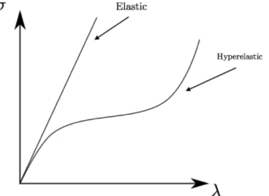
Figure 6. Phenomenological illustration of elastic and hyperelastic behavior.
The elastic behavior of different materials occur due to physical reasons. Figure 6 shows two different types of elasticity, namely linear elastic and hyperelastic, respectively. For a linear elastic material, the stress will increase linearly with increasing strain or stretch, 𝜆. However, for a hyperelastic material, the stress will deform in a non-linear fashion. Furthermore, for a hyperelastic material, the strains can be several hundred percent and it is thus more convenient to use stretch as opposed to strain. For materials like rubbers and other polymers, the stretching of polymers chains is what causes the elasticity and most these are considered as hyperelastic. For metals, the atomic lattice change size and shape when forces are applied and then goes back to its original lower energy state when the force is removed. Thus, in the elastic phase of deformation for metals, they are considered linear elastic. The internal resistance to the deformations in the materals that restores it to its original shape after the external force no longer is applied is called elastic modulus. This varies between materials [19]. The behavior of a material is commonly described by a stress-strain curve. The curve shows the relation between the average restorative internal force per unit area (stress) and the relative deformation (strain) [20]. The curve is generally nonlinear, but it can be approximated as linear for small deformations. If the material is isotropic (uniformity in all orientations), the relationship between stress and strain is called Hooke’s Law for small deformations. This law can be stated as a relation between tensile force and the corresponding
2.3.2 The Ogden material model
In 1972, Ray W. Ogden created a model called “The Ogden material model” for hyperelastic materials. It is used for complex materials such as biological tissues. The model assumes that the material behaviour can be described by means of a strain energy density function from which the stress-stretch relationship can be derived. The Ogden material model expressed in terms of the principal stretches 𝜆!:
𝑊 𝜆!, 𝜆!, 𝜆! = 𝜇! 𝛼! ! !!! ( 𝜆!!!+ 𝜆 ! !!+ 𝜆 ! !! ) Where N, 𝜇! and 𝛼! are material constants [23].
For the PEOPLE project, the lower limb has been chosen as the body part for the finite element analysis. The human lower limb consists of many different materials such as skin, blood vessels, bone, muscle, fat, blood, etc, and they all have different properties. For example,
• Human muscle is considered an anisotropic (a difference in a material’s physical or mechanical properties when measured along an axis [24]) and viscoelastic material (materials that exhibits both viscous and elastic characteristics when undergoing deformation [25])
• Fat has been shown to exhibit nonlinear, anisotropic and viscoelastic behaviour • Skin exhibits complex, anisotropic and nonlinear mechanical properties
• The fascia (a band of sheet of connective tissue that encloses and separates muscles and other internal organs, primarily contains collagen [26]) is modelled as an incompressible material using the polynomial strain energy function
• The tibia (the shinbone) and the fibula (calf bone) is considered as an anisotropic organ
• The walls of the blood vessels consist of multiple layers of different denominators, collagen fibres arranged in different directions being the key ingredients, giving the vessels and anisotropic and highly nonlinear elastic properties
• The blood flowing through the vessels also have an impact since the pressure that the blood exerts as a function of time affects the model as well.
A detailed FE model should take all these factors into consideration, which makes this a complex, highly nonlinear problem. Constructing a FE model for the human body is difficult since material properties for the tissues are not always available and the material properties for the same tissue can differ from person to person.
The Ogden strain energy potential in this case is expressed as: 𝑈 = 2𝜇! 𝛼!! ! !!! 𝜆!!!!+ 𝜆 ! !!!+ 𝜆 ! !!!− 3 + 1 𝐷! ! !!! (𝐽!"− 1)!!
Where U is the strain energy per unit of reference volume,
𝜇
!,𝛼
! and𝐷
𝑖 are material constants. N is the order of the equation, 𝜆! are the deviatoric principal stretches and 𝐽𝑒𝑙 is the elastic volume ratio. The polynomial strain energy potential is expressed as:𝑈 = 𝐶
!
𝐼 − 3 !(𝐼 − 3)!+ 1 !
Theoretical background
2.3.3 Indentation of the lower limb
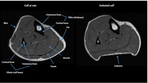
An MRI (magnetic resonance imaging) will take scans of the lower limb while it is being subjected to pressure. Then, based on how the different tissues act to that pressure, calculations that lead to simulations will be made. This is the calf of a 52-year-old male without diabetes.
Figure 7. MR image of human calf
As can be seen in Figure 7, the structure of the lower limb alters as the cylindrical indentor applies the pressure. From this, the finite elements experts can compute the different elements function and construct a model using a mesh technique.
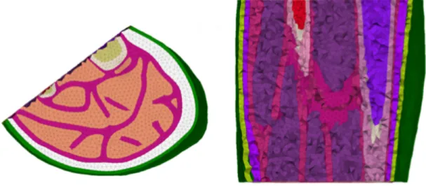
Figure 9. Cross section of the Finite Element Model
A cross section of the model is shown in Figure 9 where a clear view of how the meshing of the different tissue properties continuous throughout the calf is presented. With this model, simulations of pressure and strain can be made so that it will show how the tissues properties will react to it. As stated earlier, what makes this a highly complex problem is that the tissue properties can vary between individuals and that the blood flow as function of time exerts the model. There is a gap in research in this particular area.
General problem description
3 General problem description
HotSwap Norden is currently working on a prototype that is supposed to apply a constant pressure on the calf with a specific force during a specific amount of time while an MRI takes a photo of the tissue that later gets analysed in a FEA. One of the difficulties with a development like this is that the prototype cannot contain any metallic material in it if it is supposed to go into an MRI since those cameras are highly magnetic. That means that the calf-fixator has to be made completely in non-magnetic material. Also, MRI’s are rare and expensive and a device that is in need of a MRI is not a sustainable solution for the future. The Board of Ethical Vetting in Sweden recently approved this product idea, which means that they now have authorization to start testing the device and be able to collect data for analysing. Hopefully in the nearby future they are able to find a correlation between the tissue response during pressure and pressure ulcers so that they can use a simpler device to determine whether or not a patient is at risk of developing pressure ulcers or deep tissue injuries and then be able to prevent it. The thought behind this project is that healthy tissue, unlike unhealthy tissue has a higher elasticity and because of that, with the help of the collected data, it might be possible to detect these injuries in a simpler and less expensive way.
3.1 Redesign aspects
A problem with the prototype is that it is required that the patient has at least one calf intact. Since people with diabetes for example run at higher risk of amputation, it might be so that the patients has lost both their legs due to neuropathy and decreased blood flow and is therefore no longer eligible for testing. Since diabetic patients are one of the projects target audience, the test-rig ought to be able to be adjusted for use on other body parts and not limited to lower leg only. The calf-fixator (Figure 10) is at present solid and won’t be able to be adjusted for use on other body parts than the calf.
The rig is supposed to function by pushing an object into a muscle and deforming it while an MRI is taking pictures of what happens in the tissue.The pressure relief for the shinbones is a highly important part considering the patients comfort. Since a force of 30 Newton (N) is going to push the indenter into the calf and the calf is supposed to be fixated, the same force will push back on the shinbone. The shinbone is a sensitive part on the human body and it is therefore important to take this into consideration while creating the redesign.
To facilitate the ease of use of the product it would be desired that it is mountable. This would enable smaller packaging for shipment and storage. If the rig was easy to assemble and disassemble it would be a more sustainable product to have on the market since it would be easier to use and store. These factors will be taken into consideration while creating the redesign.
4
Theoretical framework
A basic overview of the theories that have been used for accomplishing the aim and answering the issues that is included in this thesis.
4.1 Concept generation
Concept generation is a method for designing and developing products based on the function required for the device being designed. The philosophy is fairly simple: Form follows
function. The function of the device needs to be clear and understood before the design can
take its form since conceptual design focuses on function. A primary goal in concept development is that the concept will operate as anticipated and meet the targets that have been set. Concepts may be presented in sketches, flow diagrams, sets of calculations, or in textual notes. Enough detail to model performance and show the functionality of the idea must be included such that an idea of what someday might be the product should be able to be obtained. Concept generation contributes to minimization of changes later in the production development process. Changes can be costly and time consuming and it can therefore be profitable to devote time to concept generation.
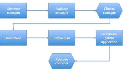
Figure 11. The conceptual design phase of the design process.
There are several steps in the conceptual design phase (Figure 11) and they do not always follow chronological order. The first three steps may be repeated several times before the selection of concepts is defined. The generation of multiple concepts increases the chance that one will be good enough for further development.
Defining the function of the product before starting on the design is an important process. The function tells what the product must do and the form or structure conveys how the product will do it. Reverse engineering is a form of product decomposition where an existing product is taken apart and analysed. This is an excellent way to understand existing products, systems, or assemblies. There are four steps in the technique for designing with function:
Theoretical framework
understanding of the design problem at hand. 3. Order the sub-functions.
Add order to the sub-functions found in step 2 based on the importance for the overall function.
4. Refine sub-functions.
Decompose the sub-function further to see if they can be further divided into sub-sub-functions. This decomposition is continued until existing objects can fulfil the function, or until new objects are needed.
There are several methods of generating concepts such as brainstorming, finding inspiration from analogies and patents, and morphology, to name a few [28, pp. 175-228].
4.1.1 Brainstorming
Brainstorming is a method of creative problem solving. It encourages creativity and thinking outside the box. A group of participants, including both experts and novices gathers with the purpose of finding a solution for a specific problem or the answer to a specific question. Ideas receive no criticism or discussion. Wild and unexpected answers are encouraged. The two principles of brainstorming are:
1. Defer judgement 2. Reach for quantity
The intention of brainstorming is to reduce social inhibitions among group members, stimulate idea generation, and increase the overall creativity of the group. By reaching for quantity, the chance of producing a radical and effective solution increases and therefore the group is encouraged to speak their minds and come up with new ideas. An important part of brainstorming is to withhold criticism. The participants should instead focus on extending ideas, adding to ideas or combining ideas. Wild ideas are also encouraged since this may help generate new perspectives. There are several types of brainstorming, where individual brainstorming is one of them. Individual brainstorming does not need a group but works in a similar way. The individual writes- or draws down the ideas instead and then make a selection of which ideas to continue with [29].
4.1.2 Product decomposition
A mechanical device is generally composed in the order system-subsystem-assembly-component. When doing a redesign it is important to dissect the product to understand how it is built and how it works. This is called product decomposition, reversed engineering or “benchmarking”. Product decomposition is highly important in the design process and can serve as a starting point no matter what type of design that is in demand [28, pp.42].
4.2 Design for component manufacture (DFCM)
Specifying the best manufacturing process for the component and ensuring that the components form supports the manufacturing process selected is a key concern in DFCM. The definition of DFCM is establishing the shape of components to allow for efficient,
high-quality manufacture. There are design guidelines for each manufacturing process that, if
4.4 Decision-matrix method (Pugh’s method)
Pugh’s method is a decision matrix that has been proven effective for comparing alternative concepts. By scoring each alternative concept relative to the others in its ability to meet the criteria, comparisons can be made amongst the concepts. This is an evaluation method that is useful in decision-making. The process is divided into 6 steps.
1. State the issue
2. Select the alternatives to be compared: The different ideas developed during the concept generation
3. Choose the criteria for comparison
4. Develop relative importance weightings: Determine the importance of the criteria 5. Evaluate alternatives: In redesign, the developed concept will be evaluated against
both the original design and the other concepts
6. Compute the satisfaction and decide what to do next: Add scores and pick concept to continue with [28, pp. 240-244].
4.5 Gantt chart
A Gantt chart is a form of flowchart that is often used in project management that illustrates a projects schedule. It is a summation breakdown of the structure of the project. It graphically illustrates how the layout of the project is distributed. It can be made in Excel as a horizontal bar graph against a timeline [30][Annex 1].
Implementation
5
Implementation
The goal with this thesis project is to create a redesign of the prototype for the lower limb pressure device such that the ease of use and the user option for both patient and staff is optimized. Both manufacturing and assembling aspects will be investigated to possibly make the device mountable and enhance user options. This chapter contains the design process.
5.1 Present design
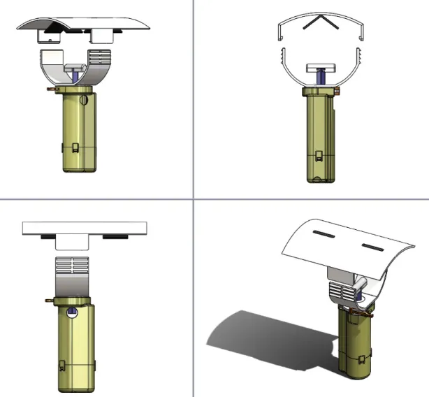
As stated earlier the present design has been developed by HotSwap Norden AB and is currently in the process of being produced. The main focus for HotSwap has been the mechanics and the design behind the part that will produce the pressure and measure the indention of the tissue. This product is supposed to be used for mere research purposes and will therefore not be a product of mass production. Some parts will be purchased from other suppliers, those that are not will be 3D-printed at the School of Engineering at Jönköping University. The final material that will be used for this product has yet not been determined. The proposition for the part that will be made of plastic is to use the material ABS (Acrylonitrile Butadiene Styrene). ABS is a co-polymer that consists of acrylonitrile, butadiene and styrene. ABS is known for being particularly tough and is used in products like lavatory seats [31]. This part will not be the subject of the redesign.
By using product decomposition on the calf-fixator it shows that it is currently designed as two components that are permanently mated together by a clicking function to form one solid component. Since the calf-fixator is not adjustable, it will not fit every patient, and if a patient does not have at least one lower limb intact, they will not be viable for the research. Furthermore, the lower limb on a human can vary substantially in size from person to person. Thus, this design limits the use of the pressure device. Further product decomposition also shows that the calf-fixator is supposed to be glued on to the pressure device part. This solution is non-adjustable and the calf-fixator will therefore not be able to be replaced if needed. An adjustable fixator would expand the research area both in terms of suitable patients for testing and different body parts for the finite element analysis. Therefore, new solutions for the calf-fixator will be explored. Since this device is going to operate on people, it is important to take that into consideration and design for a comfortable experience with optimized pressure relief. There is currently nothing to relieve the pressure for the shinbone. This is a necessity since the device is supposed to operate on humans. To enhance the ease of use, it would be preferred that the device is collapsible or mountable. This would optimize packaging, delivering and storing, and contribute to a more sustainable solution. Concept generation, brainstorming, DFA, DFCM and conceptual design will develop the concepts for these functions. The different designs will be evaluated and compared first to the original design and secondly to each other by use of Pugh’s matrices.
5.2 Designing with functions
By following the concept generation method, the first step towards creating a concept is to identify the functions that are required by the new design. Since form follows functions, it is important to thoroughly determine the desired specifications before generating design concepts.
In the remaining parts of this report, the calf-fixator will be referred to as “the chassis”.
5.3 Function Pressure relief
Two concepts for a pressure relief system were generated through brainstorming, DFA and DFCM.
Concept 1, Oval: A silicon plate bent in an oval shape to be fitted on the limb. This solution
would provide a comfort for the patient when applying the pressure device since there are no sharp edges. However, a bent plate that follows the limb would not provide a good pressure relief. The pressure that is applied from the indentor on the calf will most likely result in an equal retaliating force on the opposite side, which in this case is on the shinbone.
Concept 2, Angle: A silicon plate bent in an angle to distribute the pressure in several directions. It is known from Newton’s first law of physics that the sum of all forces on a body
in constant motion is zero. In this solution, unlike the one in the oval concept, the retaliating force will be divided into two different forces that will come from different directions since the force is always perpendicular to the surface, i.e. the shinbone. In this case the front of the shinbone will not be subjected to the force at all.
Since the production of the device is going to be 3D printing, the DFCM for both concepts are the same.
5.4 Function Mountable
Two concepts for the ability of mounting the device was generated through brainstorming, DFA and DFCM.
Concept 1, Screw: A system similar to that of a cap of a soda can. That way the chassis can
easily be screwed both on and off. This solution would optimize the ease of use substantially and also contribute to a more sustainable solution since the chassis will be easy to replace if needed.
Concept 2, Click: A form of “clicking into place” system. This will also optimize the ease of
use in that case that the chassis will be replaceable. However, a solution like this might be a bit more complicated to take apart. Also, a clicking solution might have a shorter lifespan due to fatigue in the material caused by replacing or exchanging the chassis.
Since the production of the device is going to be 3D printing, the DFCM for both concepts are the same.
Implementation
5.5 Function Adjustable
Three concepts for the chassis being adjustable were generated through brainstorming, DFA and DFCM. All three concepts for this function will contain the final concepts for the function pressure relief and the function mountable that will be presented in Results and discussion. Therefore, all the chassis are removable and replaceable and have the same pressure relief systems. All three concepts will also serve the same purpose as the original design and will offer at least all the functions that the original prototype offers.
The adjustable function has more criterions to take into consideration than the two previous functions. The list of desired criterions for the design:
• Range of use: Ability to use the device on different body parts. • Storage possibilities: Ability of the product to be easily stored. • Replaceable parts: Ability to replace the different parts. • Comfort for patient: Comfort properties.
• Ease of fitting: Ease for both patient and staff when fitting the patient. • Fit on the limb: Better fit properties.
• Easy assemble: Assembling properties.
• Keep limb in place: Ability to keep limb from shifting during pressure.
• Packaging possibilities: The ability of the product to be easily packaged and shipped. The manufacturing costs will not be taken into consideration since the pressure device will only be produced in small volumes and there will not be a significant difference between the concepts.
5.5.1 Concept 1, Solid
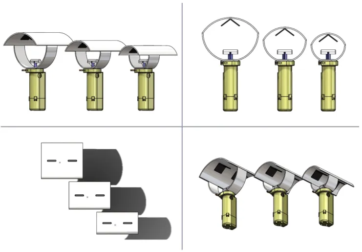
This concept is similar to the original design in that way that it is solid and non-adjustable (Figure 12). This concept however comes in three sizes, one that is meant for the arm, one for the calf, and one for a bigger muscle, like a thigh. This expands the use of the product since it is no longer limited to lower limb only. However, since all the parts are solid, the device is still limited. Also, to be fitted on the patient, it has to be pulled over the foot, which can be perceived as uncomfortable for the patient. The shape of human limbs can differ substantially from person to person, and this prototype might not fit all patients. Thus, this concept might still limit the research area.
Implementation
5.5.2 Concept 2, Clicker
This concept is a two-piece concept. As can be seen in Figure 13 it has a clicking system, which makes it adjustable. It has four different stops and a plug in the middle, which will hold the top part in place and keep it from sliding from side to side. With this function, the width of the adjustment is 4 cm. Also, the bottom part has larger radius than the original, which indicates that the use of the product is wider than that of the original. Though the use of this product is wider, it still limits the use to certain shapes of limbs. Thus, this concept is not optimal for fairly small or large limbs.
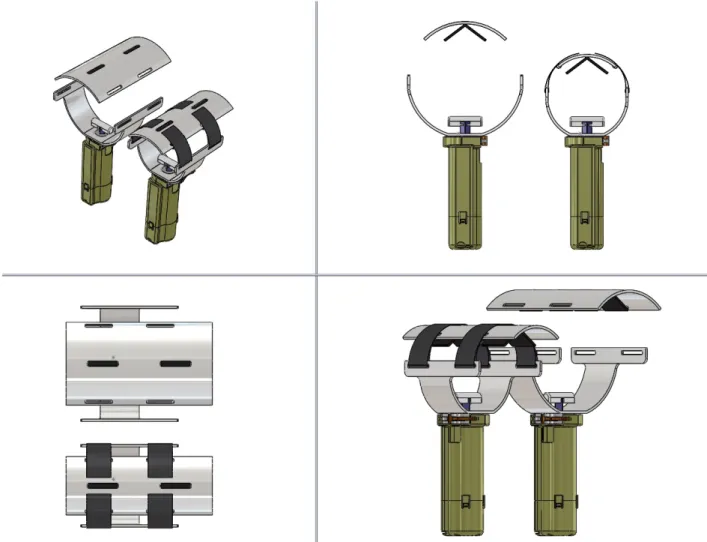
5.5.3 Concept 3, Velcro strap
This concept is also a two-piece concept. The difference with this concept compared to concept 2 is the fitting function. This concept consists of two independent pieces that are fixed together by a Velcro strap (Figure 14). The Velcro strap makes this concepts highly adjustable and easy to put on and take off the patient. Since the Velcro straps are easily altered to fit the patient, both the comfort and the ease of use is more optimized compared to the original design. The concept comes in two different sizes, one smaller to be fitted on an arm or a calf, and one larger for a thigh. Both storing- and packaging possibilties are optimized as well since the device can be taken apart. However, since the device is being 3D printed, the Velcro straps add one more step in the manufacturing process since this part won’t be printed. The Velcro strap will not be manufactured within the project and needs to purchased from an outside distributer. Also, a downside with the larger alternative is that the top part might be to slim. If it is suppose to fit on a thigh, that is much softer on the top than a calf, the edges might be uncomfortable for the patient. If this concept is the one to be chosen, this will be taken into consideration before presenting the final design proposal.
Figure 14. Concept 3, Velcro strap, for function adjustable.
Results and discussion
6
Results and discussion
This report was based on two specific issues that were stated in the first chapter. The results of these issues have been answered through research, concept generation, conceptual design, DFA, and brainstorming to name a few. The project of gathering information and writing the report was distributed over 15 weeks with the help of a Gantt chart [see Annex 1]. In the following chapter, the results of the issues are presented.
6.1 For whom and in what purpose would a device like this be
necessary?
The problem with pressure ulcers in the healthcare sector is growing due to the increase in the mean life expectancy for the average human, and an increase in people diagnosed with diabetes. People with diabetes have a poorer blood flow than that of healthy people and therefore, due to the oxygen shortage in the tissues, run at higher risk of amputations. The amputees that are in need of artificial limbs are often victims of pressure ulcer due to high and prolonged pressures where the prosthetic sockets are located. The likelihood of getting a pressure ulcer, and the severity of the same, varies greatly from person to person. The reasons for this are still unknown. This is the main reason why the PEOPLE project started at Jönköping University, the only school in Sweden where it is possible to get a Bachelor’s degree in orthopaedic engineering. The long-term aim of the project is to optimize the development of prosthetic limbs. However, the issue of pressure ulcers does not only affect the people in need of artificial limbs, but it is also a general problem for patients that are unable to move by themselves, people that are in a coma, that are fully or partially paralyzed, or that undergo long surgeries. A way of knowing the risk of pressure ulcers could also affect the medical staff since they are the ones that have to help the patient to move if they are unable to do so by themselves. If a method of predicting who might be in the risk zone of developing pressure ulcers was found, pressure ulcers might be possible to prevent. The research in this field is important and if successful, could aid to improve the quality of life of many patients. If it was possible to categorize patients to who might be more at risk of developing pressure ulcers, then the distribution of care for the patients can be optimized and more effective. It would also facilitate the physical work for the caregivers and therefore contribute to a more sustainable workplace.
6.2 How could a device like this look and function?
A re-design of a lower limb pressure device has been developed by use of product decomposition, concept generation, brainstorming, conceptual design, Pugh-matrix, DFA, and DFCM. The weight of the criterions used in the Pugh matrices were all set by the writer of this thesis based on the importance of the desired sub-functions of the redesign gathered from both the PEOPLE project and HotSwap Norden AB. It is clear that the redesign will function in a clinical environment and in close proximity to an MRI scan since the chassis being produced is in plastic and is therefore not magnetic. The chosen material of the device will be ABS [31], the same as the one being used for the pressure device part because of its hard and non-fragile properties.
6.2.1 Function Pressure Relief
To decide which concept to pursue with, a decision-matrix in the form of Pugh’s method was used. The weight of the importance and the weight of the alternatives meeting the criteria were distributed from 1-10 by the fixed sum method. This means that the total amount of numbers to be distributed is fixed, i.e. 10, and distributed with respect to the importance of the desired results. To get the result one simply multiplies the weight of the criteria with the ability of the concept to meet the criteria and then add them together to get the final score. In this case concept 2, the angled option, is the best one to continue with since its ability to meet the requirements were higher than that of concept 1.
Figure 15. Pugh-matrix for Function pressure relief.
Figure 16. Cross-section of the final design for the angled pressure relief system that will be
Results and discussion
6.2.2 Function Mountable
To decide which concept to pursue with, a decision-matrix in the form of Pugh’s method was used. The method is used in the same way as previously explained. The same calculation process as in the previous decision-matrix has been used to determine which concept meets the criteria best. In this case concept 1, the screw cap system, is the better alternative of the two.
6.2.3 Function Adjustable
The importance of the criteria’s listed in chapter 5.5 will be distributed by the fixed sum method as well as the ability of the different concepts to meet these. The fixed sum in this case will be 100 instead of 10 as in the previous cases due to more criteria’s. The decision-matrix shows that concept 3, the Velcro strap (Figure 14), best met the requirements and will therefore be the concept to continue with for the final design proposal.
Conclusions
7
Conclusions
It is irrefutable that a device of this sort is necessary for further research in the field of pressure ulcers. Furthermore, the research itself, if successful, would change current medical decision-making. It is therefore highly important that the pressure device is optimized to its fullest potential when the trials start. The final concept generated in this report fulfils all the desired functions of the redesign. The theories that were used to create and generate the idea are all well-known in design and have been proven highly productive which strengthens the belief that the work is reliable and valid.
7.1 Final concept
The final result of the concept generation contains the best concepts for the different desired functions. The difference between the re-design and the original design is that it is adjustable, mountable and comfortable. Due to the desired requirements on the final conceptual design, a Velcro strap has been utilized to enable optimal adjustability of the device, a pressure relief system has been developed, and a screw system for mounting of the device has been constructed. Furthermore, the re-design is now adaptable for use of any type of patient and no longer limited to lower limb only.
The final concept has been furthered improved after the concept generation to be even more adjustable. An additional hole for the Velcro strap, which will increase the adjustability of the device even further, has been added on both prototypes (Figure 20). Also, the larger prototype’s top part has been improved by an increase of the radius and an expansion of the width (Figure 21). This will optimize the comfort for the patient when used on a thigh. The edges that will come in contact with the patient have all been rounded for comfort. To fasten the device around the limb, the Velcro straps will be wrapped and fasten on top of each other.
Figure 21. Final concept for the large prototype without the Velcro strap
Another positive aspect of this design is that it is fairly simple. This implicates that it is easily altered if needed. Since the PEOPLE project is partially based on Jönköping University, and they are the ones in possession of the 3D printer as well as they have access to computer aided design programmes (CAD), it makes alterations to the chassis easily accessible. This expands the user opportunities for the future use of the device. Since the Velcro straps are highly adjustable, all that is needed might be alterations of the chassis. This could enable the research to stretch even further and might even extend to the scans of the gluteus muscles. Though, if to be able to fit around the hips of a patient, several alterations to the top part and pressure relief system have to be made, as well as a substantial increase in the length of the Velcro strap. This has to be investigated further before a prototype can be designed, but it might be a possibility in the future.
7.1.1 Implications
An implication with this concept is that it might not be as effective as wanted for this purpose. If tightened too much, it might compromise the effect that the indention makes. Since the force of 30 N is a fairly small force, others forces might have an effect on the outcome. This might compromise the finite element analysis and contribute to inaccurate and unreliable results since deformations will occur uniformly around the limb. It is possible to incorporate the different deformations into the analysis but it would increase the models complexity and make it harder to analyse. However, if not tightened enough, the limb might move during the indention and might therefore differ from the first scan without the indention. If that happened, it might also compromise the finite elements analysis since the scans might differ in location. This device is also still fictional, so the comfort and stability is only speculated on so far, though with strong credibility. Also, the pressure relief system could be optimized further. When reviewing the concept for the angled system, it showed that it was more optimal for smaller limbs, such like arms or shinbones, than larger limbs, like a thigh. A solution for this problem would be to have several exchangeable pressure relief systems in
![Figure 2. Schematic images of pressure ulcers stages [Figure 2]](https://thumb-eu.123doks.com/thumbv2/5dokorg/5470263.142321/12.892.147.743.121.521/figure-schematic-images-pressure-ulcers-stages-figure.webp)
![Figure 4. Body regions particularly exposed to external pressure [Figure 4]](https://thumb-eu.123doks.com/thumbv2/5dokorg/5470263.142321/13.892.138.765.104.644/figure-body-regions-particularly-exposed-external-pressure-figure.webp)
![Figure 5. Reswick and Roger Curve and Sigmoid injury threshold for pressure ulcers [Figure 5]](https://thumb-eu.123doks.com/thumbv2/5dokorg/5470263.142321/14.892.119.788.243.565/figure-reswick-roger-curve-sigmoid-threshold-pressure-figure.webp)