http://www.diva-portal.org
Postprint
This is the accepted version of a paper presented at IEEM2017, International Conference on
Industrial Engineering and Engineering Management, 10-13 December, 2017, Singapore.
Citation for the original published paper:
Heikkinen, T., Johansson, J., Elgh, F. (2017)
Extended CAD-models – State of Practice within Three Companies.
In: IEEM2017, International Conference on Industrial Engineering and Engineering
Management, 10-13 December, 2017, Singapore
N.B. When citing this work, cite the original published paper.
Permanent link to this version:
Extended CAD-models – State of Practice within Three Companies
T. Heikkinen1, J. Johansson1, F. Elgh11Department of Product development, Jönköping University, Jönköping, Sweden (tim.heikkinen@ju.se)
Abstract
-
Product platforms and product family design have been recognized as successful methods to enable mass-customization strategies. However, companies working with products where pre-defined product variants are not feasible require a more generic platform with re-usable components as well as engineering resources. Extended CAD-models is an approach where CAD-models are utilized as carriers of information to support re-usability of both geometric content and engineering activities, decreasing product development lead-time and enabling the definition of a product family within Engineer-To-Order business contexts. The following paper presents the approach in more detail and the results of a multi-case study where three Swedish industrial companies were interviewed. Results show that all companies store information within the CAD-models to support re-usability. Several challenges were expressed such as managing responsibilities and modeling flexible CAD-models. Future trends involve the concept, but to which extent is not clear.Keywords - Extended CAD-model, Platform strategy, State of practice
I. INTRODUCTION
Customers have shown an increased demand for customization of products. For this reason, some companies try to increase their market share by creating an ability to offer more product variants. One way of decreasing the internal company costs of more product variants is to engage in platform based product development and product family design [1]. This has traditionally been done by focusing on creating commonality between product variants and leveraging these as much as possible to target a specific market share, in order to efficiently utilize and standardize manufacturing processes and machinery. More recent attempts at expanding the platform concept have come to include commonality in the design stage as well. This has, however, required the use of more abstract building stones than predefined components, such as resources relating to engineering [2]. Extended CAD-models, as introduced in this paper, are essentially traditional CAD-models, i.e. models used to portray the final product form, with additional information not limited to the geometry-modeling discipline. They aim to support re-usability of CAD-models, decreasing product development lead-time and supporting a product
platform and product family approach within Engineer-To-Order (ETO) companies.
Since CAD systems today are capable of representing more than geometric entities within CAD-models [3] the concept of Extended CAD-models has been used. Reference [4] present it as a central carrier of information for the purpose of integrating "… the knowledge used and generated during the product design". Reference [5] describes the use of annotations on CAD-models, drawing similarities to the text-based document Markup approach where the purpose is "… to allow computers to manipulate and deal with the contents of the Web on a more sophisticated (abstract) level". Reference [6] utilize the approach to capture evolving constraints, which could be used to retrace decisions made. The approach is later elaborated by storing the added information outside the CAD-models together with lightweight representations of the geometry, making it easier for more disciplines to work with. Although there are several examples where the CAD-model is used as a carrier of multidisciplinary information, there is a lack of structured guidelines for how this can be done.
This paper presents the results of a multi-case study from three Swedish industrial companies. The aim was to explore how CAD-models are used as carriers of multidisciplinary information (referred to as Extend CAD-models, see Fig. 1) as well as what the needs, challenges, and trends are. Each of the companies works within ETO related business contexts. The rest of the paper is structured as follows; Section II presents the empirical collection method used, Section III outlines the results, and finally, Section IV discusses and Section V concludes the state of practice extracted from them.
Fig. 1. Extended CAD-model concept. Extensions are indicated with black interfaces which can be used to link other disciplines.
II. METHODOLOGY
To get an understanding of the detailed state of practice and future trends of Extended CAD-models, three large Swedish industrial companies with a long history of extending CAD-models were investigated using interviews. Nine employees from different disciplines and positions, which were in some way connected to the extension of CAD-models, were selected to get several perspectives on the matter. The questions were structured to first focus on personal practice, followed by company-wide practice, and finally personal perceptions of trends. The interview was not fully structured, meaning that flexibility in the way that questions was expressed varied and sometimes skipped or even new questions added when interesting topics arose. In the end, a total of about 4,5hours of recorded interview material was collected. An analysis was conducted by replaying the audio from the interview sessions. First, each response to the questions was transcribed, categorized and then summarized for each company. The final results are presented in Section III.
III. RESULTS
The results and analysis are first divided into subsections (A-C) according to the three case-companies. It starts with a small introduction about the company and is then progressed by a summary of why and how they utilize CAD-models as carriers of information along with challenges and future trends expressed. Section D then summarizes the extension techniques extracted.
A. Company I
The studied company develops and manufactures products that support an active life style. Some of the products are transport centered, e.g. roof-boxes and bike carriers. It makes roof racks for cars an important product for the company which also has been the target for this case study. Each roof-rack is engineered to meet the unique geometric specifications of each car. There was one interview conducted at this company with a consultant who works within both the geometric-modeling and simulation discipline. The interviewer's main responsibility was to enable automation of different kinds and worked with CAD- (Solidworks), simulation-, and automation-system types.
Two different reasons for adding information to the CAD-model could be identified, both to enable automation. Geometry and programmed features (called macro-features in Solidworks) were added to store information relating to the simulation discipline to fully automate the creation of a Finite Element (FE) model. The programmed feature provided a way for the user to specify a FE-feature, either to add a definition or a mesh-component. Geometry was added when necessary and could be constrained to the traditional CAD-model, it could then be pointed at from the programmed feature which required it. In the second automation system, section-curves
were added to the CAD-model to enable a geometric-search for previous solutions which might be possible to reuse.
In both cases, described above, the logic for how to interpret the information and utilize it, to produce a FE-model or retrieve re-usable solutions, was modeled outside and enabled as add-ins within the CAD-software. To make the insertion of programmed features user-friendly a number of graphical user interfaces were made.
Methods for the utilization of the automated FE-model creation system is under development and well established for the geometric search system.
The main challenges in both automation-cases were said to be organizational. Only the first automation-system had been successfully implemented so far and the main reasons for this were believed to be the visualization of the search-process and integration within the existing system [7]. The second automation application is still under development but concerns relating to responsibilities by adding the additional information were expressed. Geometric modelers working in CAD did not feel like adding information relating to another discipline, in this case, the simulation discipline, and employees in the simulation discipline did not want to work in the CAD environment.
B. Company II
Company II is a supplier of tools, tooling solutions, and know-how to the metalworking industry. This case-study focused on a part of the company which develops parametrically defined product families with fully automated production specifications. Siemens NX is the used CAD software. Three interviews were carried out, each with different positions within the company. Their positions were geometry-modeler, methods developer within automated geometry modeling, and method developer within geometry-modeling. The geometry-modelers utilized mainly CAD but also some simulation software to model the geometry of the tool bodies. The methods developer within automated geometry modeling utilized CAD, Office products, PLM, and Automation software. The employee's main responsibilities were to check whether technologies proposed within new technology development projects already had been proposed and developed as well as further develop the methods utilized. The methods developer within geometry-modeling utilized CAD, PLM and Microsoft Office to standardize geometry-modeling methods, to ease the introduction of new employees and to ease the re-usability of CAD-models within CAD, CAM, CMM, and design automation software.
The main reason for adding non-traditional information to the CAD-model was to ease re-usability of it within CAD, CAM, CMM and even customer's simulation software. Information was added in the form of reference planes, parameters, names, attributes, and geometry. Most of the CAD-models were then saved as User-Defined-Features (bundles of features) with the reference planes and parameters as input. An example of the added information could be the addition of a point with tolerance information stored as
attributes subsequently used by an automated system and interactively by engineers. The automation system utilizes the information to build up the final product CAD-model, supporting CAD-models for CAM and CMM, as well as simplified models for customer's simulation software. It also simultaneously adds more information to the different parts. The software is built with a company specific programing language which is built upon the CAD-software API. Another software which has been added to aid in this endeavor is under development, it is intended to ease with the addition of annotations within the CAD-software.
Methods about how to model, including the naming-nomenclature and what names to put where have been documented. It is not entirely complete and is under development.
Challenges were expressed about dealing with changes, knowing what information to add, keeping UDF's simple, knowing what customers want, and persuading geometry-modelers to administer the nongeometric information modeling as well.
A trend can be seen where the information is moving from the CAD-models to the design software. Even though the information ends up in the CAD-model the hope is that anyone utilizing the information looks at the "receipt" within the automation system instead. But some added information for "handles" of CAD-models will probably always be needed. C. Company III
Company III is a global actor in development, production, service, and maintenance of components for aircraft, rocket, and gas turbine engines. They provide products that are completely custom engineered in an international market with high competition. Siemens NX is the main CAD software. Five interviews were conducted with employees at the company. Four of the employees were structural analysts working within both technology and product development, focusing on both automation methods for meshing and/or solving. They all worked with automation of engineering processes in some way. One did not use CAD, one used process management software, and all used simulation software. The fifth employee was a geometry-modeler within technology development working with parametric shell and solid models utilizing CAD, a little simulation, and automation software. This employee's responsibility was to maintain and create parametric CAD-models for automated variant creation.
The main reasons for adding non-traditional information to the CAD-models was to enable automated creation of CAD and FE models. It is done by adding attributes to convey FE model specific features such as thicknesses (for shell models), material id, mesh quality, contact interface, loads, boundary conditions, thermal-analysis information etc., on e.g. points, lines, surfaces, and solids. Names are also added, to for instance convey mesh components and as handles to automate the addition of most of the non-traditional CAD information described here. New geometric entities are also added, such as
points (to convey load interfaces) and surface bodies (to convey boundary conditions). Programmed features (Knowledge Fusion® objects) are added to read from spreadsheets and alter parameter values according to the information. Finally, parameters are also added to modify the geometry. For the automated creation of variations of the parametric CAD-models, an initial assembly had been made with around four sub-components connected through wave-links (a way to re-use geometric entities between components), each with some surface-body names and parameters. Scripts had then been made to read the initial parameter values from a spreadsheet for each variant and alter these accordingly. They are then propagated down through the assembly structure by activating the other components one by one. Names are then read from the spreadsheet and modified or added to more geometric entities such as faces, edges, and points. Finally, attributes are also read and added through the spreadsheet. For the automated FE model creation, a built-in Hypermesh function is used to read native Siemens NX files, it gets geometric entities (points, lines, surfaces) with names and added attributes.
Several different scripts have been added to enable the automated process of CAD-model manipulation and synthesis as well as FE model creation. Including scripts to read and write from text and spreadsheet files, quality checks by altering colors of geometric entities with the correct non-traditional information, interpret and model FE-models from imported CAD-models in the pre-processor, and visualization of simulation progress.
Methods have been made to describe the nomenclature for names and attributes and how to work with the automated meshing method. Methods for the automated CAD-model creation is being developed.
The challenges expressed were managing the tradeoffs between mesh quality and size as well as CAD-model simplicity and fidelity, setting up the initial parametric CAD-model, and managing software updates.
With respect to Extended CAD-model trends, all participants agreed that if automated CAD- and corresponding FE-model creation is to be used some non-traditional CAD-model information will be required. Most participants also mentioned that such a trend is being noticed.
D. CAD-model extension techniques
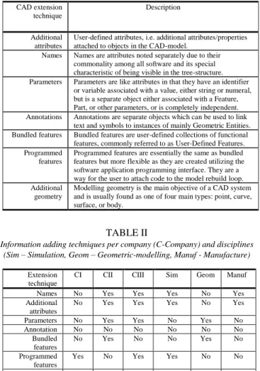
Extended models are essentially traditional CAD-models, i.e. models used to portray the final product form, with additional information not limited to the geometry-modeling discipline. There are many ways that multidisciplinary information can be added to the CAD-model, Table I specifies the different approaches extracted from the interviews.
TABLE I
Information adding techniques
TABLE II
Information adding techniques per company (C-Company) and disciplines (Sim – Simulation, Geom – Geometric-modelling, Manuf - Manufacture)
Extension technique
CI CII CIII Sim Geom Manuf
Names No Yes Yes Yes No Yes
Additional attributes
No Yes Yes Yes No Yes
Parameters No Yes Yes No Yes No
Annotation No No No No No No Bundled features No Yes No No Yes No Programmed features
Yes No Yes Yes No No
Additional geometry
Yes Yes Yes Yes Yes Yes
IV. DISCUSSION
Using Table I makes it possible to compare the three companies and disciplines, as depicted in Table II. During the interviews, a common discussion was whether the additional information should be a part of the CAD-model or simply linked to it, this is therefore discussed further in subsection A below, followed by discussions regarding the different approaches, challenges, and support systems developed, printed in subsections B-D.
A. Link or store inside CAD-models
One thing to contemplate is to which extent the CAD-model needs to be extended with information. In many of the interviews only several initial "handles" to the CAD-models were expressed as necessary. The question is how much flexibility in the modeling procedures that should be allowed or is necessary, not to hinder the multidisciplinary work. In all cases, several geometric entities were required to be added. They represented positions from which loads could be specified, tolerance information stored, boundary conditions set, geometry which FE features were to work with, and
manufacturing specifics to be copied and stored. CAD-software originate from its ability to create and visualize geometry and for this reason might be easiest to model and store inside the CAD-models. Some handles to geometric entities might also be a good idea.
Company I never added FE model specifics, such as meshing quality and load cases, to the CAD-models. Company II emphasized that most of the information was pushed outside the CAD-models and instead a part of the automation code, also described as the "recipe", for the different product configurations. The information was always channeled through the CAD-models however, even though this was not considered a must. Company III also stored most of its information outside the CAD-models, just as in the second company only information handles for different parts were added. In this case, the information was also channeled through the CAD-model however for utilization in other disciplines. The information was used for FE model creation and the information regarding the pre- and post-processing activities were saved as templates outside the CAD-models.
B. Different approaches and purposes
The different disciplines that utilized the CAD-model as a carrier of information were geometric-modelers, simulation, and manufacturing. Each mainly to enable automation of different tasks. The geometric modeler needed handles on parameters and reference planes to combine the different parts. The simulation discipline needed FE specific information relating to the geometric entities as well as simplified representations of the actual product form, this was added in the form of names, attributes, geometric entities, and programmed features. Manufacturing needed complementary CAD-models representing the manufacturing equipment and tools, as well as process specific information. This was made possible by adding names, attributes, geometric entities (e.g. point with tolerance information), and entirely new CAD-models.
C. Challenges
Regarding the methods brought up they were all directed towards geometric-modelers who were thought of as the responsible person to add all the information, even though it was utilized by others. The methods were not always complete and sometimes hard to use because of a large amount of information in them. Utilizing nomenclatures was one aspect which made this difficult. Only Company I was free from the management of a naming convention (nomenclature) between the different disciplines. In this case, the programmed features provided interfaces for inserting the information.
In addition to the challenge regarding methods discussed above, a challenge expressed in two of the companies was the resentment to administer the addition of the information. Geometric-modelers ask themselves "what is in it for me" when required to administer multidisciplinary information, and other disciplines do not want to work in the CAD-software
CAD extension technique
Description
Additional attributes
User-defined attributes, i.e. additional attributes/properties attached to objects in the CAD-model.
Names Names are attributes noted separately due to their commonality among all software and its special characteristic of being visible in the tree-structure. Parameters Parameters are like attributes in that they have an identifier
or variable associated with a value, either string or numeral, but is a separate object either associated with a Feature, Part, or other parameters, or is completely independent. Annotations Annotations are separate objects which can be used to link
text and symbols to instances of mainly Geometric Entities. Bundled features Bundled features are user-defined collections of functional
features, commonly referred to as User-Defined Features. Programmed
features
Programmed features are essentially the same as bundled features but more flexible as they are created utilizing the software application programming interface. They are a way for the user to attach code to the model rebuild loop. Additional
geometry
Modelling geometry is the main objective of a CAD system and is usually found as one of four main types: point, curve, surface, or body.
or may not have access to a license. An interesting approach to challenge this issue might be lightweight representations of the geometry outside the CAD-software with information adding to geometric entities which could also be read within the CAD-software [8]. This approach also would not require the addition of several new licenses, if any.
Other challenges were also expressed regarding software updates, modeling robust and flexible CAD-models, and managing the tradeoffs between mesh quality and size as well as geometric simplicity and realistic product representations. All of which are duly noted. When it comes to the management of the trade-off between geometric simplicity and realistic product representation, both Company I and II had methods where both models were represented. Company I focused on the definition of FE features from within the CAD-software utilizing the creation of new geometric entities, constrained to the product CAD-model. Company II had automated the product model creation process and could therefore skip different parts of the modeling to produce simplified models for simulation purposes.
D. Support systems
Many different support systems have been made to work with Extended CAD-models. All companies utilized some sort of script or software to ease with the adding of information for geometric-modelers. Company I utilized programmed features which are instantiated using CAD-software internal user interfaces with predefined inputs for different FE features. Company II had an automation system built upon the CAD-software API which added information at the same time as it merged the different CAD-models. Company III also had different scripts to read from spreadsheets and automatically add names and attributes once the final product model had been created, in this case, CAD internal scripts has been made and added to the different CAD-models and executed by a CAD-software macro.
V. CONCLUSION
The results show that CAD-models are a central part of the product development process within the case-companies. This is most likely because CAD-software is the main tool utilized to build and visualize the 3D representation of geometry. All three companies add information to the CAD-models to ease re-usability, some to visualize and store information relevant for human users and all to enable machine manipulation and extraction of the CAD-model information. Being able to automatically manipulate the CAD-models have resulted in the formalization of engineering activities into scripts and software. Such information could be a part of the generic platform utilized to implicitly define the feasible product configurations (i.e. product families) supporting mass customization within ETO business contexts. Automated manipulation of the CAD-models is found from several different disciplines and the information is added in several different ways. Methods are available but sometimes
incomplete or difficult to use. Other challenges are concerning who should add and be responsible for the added information, managing software updates, modeling of flexible CAD-models, and managing trade-offs between realistic product representation and simplified geometry. All the studied companies have developed some support, either resulting in the information being stored outside and automatically inserted or simply made easier to insert from within the CAD-software itself. Finally, every company in this study saw a trend in which Extended CAD-models were a part. However, to which extent the information should be a part of or linked is still not clear. Future work will focus on developing guidelines through a prescriptive phase where the challenges expressed are addressed by developing applications.
ACKNOWLEDGMENTS
The work has partly been carried out within the project ProAct (Platform Models for Agile Product Development: Building an Ability to Adapt), financed by the Region Jönköping County and Jönköping University.
REFERENCES
[1] Z. Pirmoradi, G. G. Wang, T. W. Simpson, Advances in Product Family and Product Platform Design: Methods & Applications, Springer, ch. 1, pp. 1–46, 2014.
[2] F. Elgh, S. E. André, J. Johansson, R. Stolt, "Design Platform - Setting the scope and introducing the concept", in Proceedings of International Design Conference, DESIGN DS 84, pp. 1253-1264.
[3] S. K. Chandrasegaran, K. Ramani, R. D. Sriram, I. Horváth, A. Bernard, R. F. Harik, W. Gao, "The evolution, challenges, and future of knowledge representation in product design systems", CAD Computer Aided Design, vol. 45, no. 2, pp. 204–228, 2013.
[4] Bojcetic, N. Pavkovic, N. Pavlic, D., "Extended CAD model", in Proceedings ICED 05, the 15th International Conference on Engineering Design.
[5] McMahon, C. A. Davies, D., "The use of annotation in design representation", Design Methods for Practice - 5th International Seminar and Workshop of Engineering Design Integrated Product Development, EDIProD 2006.
[6] Ding, L. Matthews, J. Mullineux, G., "Capturing constraint evolution: A technique to preserve and handle design knowledge", International Journal of Product Development, vol. 15, no. 1–3, pp. 135–155, 2011.
[7] Johansson, J. Cederfeldt, M., "Interactive Case Based Reasoning through Visual Representation: Supporting the Reuse of Components in variant-rich products", in Proceedings of Design2012, pp. 1477–1485.
[8] Ding, L. Davies, D. McMahon, C. A., "The integration of lightweight representation and annotation for collaborative design representation", Research in Engineering Design, vol. 20, no. 3, pp. 185–200, 2009.