1
ERRATA
page,line 2
11
says:
ratio BR(pp
-+1I"°W
+
1I"
0p
o
+ 11"°11
+
1I"°11')/BR(pp
-+11W
+
11po+
1111
+
1111') an upper
limit of 0.50 could in addition be
reads:
ratio BR(pp
-+11W
+
11po+
1111
+
1111') /BR(pp
-+1I"°W
+
11"0pO+ 11"°11
+
11"°11')
an upper
limit of 0.50 could in addition be
page,line 18
last
should be ommitted
page 55
should be replaced witdh with figure on next page
page,line 57
5
says:
UMERTO, ECO
It nome della rosa
reads:
UMBERTO, ECO
It nome della rosa
Reference
14
says:
14.
E. S. Birger, B. O. Kerbikov and I. S. Shapiro, Yad. Fiz. 17(1973)1321 (Sov.
J. Nucl.
Phys. bf 17(1973)92).
O. D. Dalkarov et. al., Yad. Fiz. 17(1973)1321 (Sov.
J. Nuel. Phys. 17(1973)688).
reads:
14.
E. S. Birger, B. O. Kerbikov and
I.
S. Shapiro, Yad. Fiz. 17(1973)178 (Sov.
J. Nuel. Phys.
17(1973)92).
O. D. Dalkarov et. al., Yad. Fiz. 17(1973)1321 (Sov. J. Nuel. Phys. 17(1973)688).
Reference
44
has been omitted.
It
reads:
44.
B. S. Skagerstam and A. Stern, Z. physik,C5(1980)347.
SEARCH FOR RARE NEUTRAL TWO-BODY
CHANNELS IN THE
pp
ANNIHILATION AT REST
performed by
measurements of high energy ,-rays
using a modular NaI(Tf)-spectrometer
Lars Adiels
STOCKHOLM 1986Institute of Technology, Department of Physics, and Research Institute of Physics, Stockholm
1986).
Abstract
Proton-antiproton annihilation at rest in liquid hydrogen has been studied with a modu-lar NaI(T£b-spectrometer. For the purely neutral two-body channels the following branching ratios, some of them not known before, have been obtained:
BR(pp-+
1I"°w)
= (2.38 ± 0.65)%, BR(pp-+11"0,,) = (0.82 ± 0.10)%,BR(pp -+ 11"0'1)
=
(0.0015 ± 0.007)% and BR(pp-+11"011"0)=
(0.06 ± 0.04)%.The upper limit for the branching ratio BR(pp-+ 11"0,,') was found to be 1.1%. For the
ratio BR(pp-+
1I"°W
+
1I"0po+
11"0"+
1I"0,,')/BR(pp -+"w
+
"po+ ""
+ ",,')
an upper limit of 0.50 could in addition be obtained.Itwas also concluded that a substantial part of the annihilation comes from P-wave processes.In a search for Baryonium or other exotic states, peaks appeared in the singles gamma spectrum corresponding to four possible states with masses 1210±5, 1638±3, 1694 ± 2 and 1771 ± 1 MeV, respectively, with yields having upper limits of 0.1, 0.3, 0.16 and 0.18 %, respectively. Two of these peaks are consistent with data obtained from pRe annihilation. A considerable effort was made to establish the existence of Baryonium created in pp annihilation but it must be concluded that the yield of such states, if they are narrow, seems to be much lower than anticipated. Possible interpretations of these results are briefly discussed.
A pilot experiment for further studies of the 11"0 and the" spectra at LEAR waS also performed.
Descriptors: Barionium, I-ray spectorscopy, pp annihilation at rest, pRe annihilation at rest, Glueballs.
ISBN 91-7170-986-X Sundt Offset Stockholm
"Jag skall beratta vad jag hort om glas och da skall ni forsta. I varje glas som star tillrackligt lange oberort forflyttas glasets blasa efterhand oandligt sakta mot en annan punkt i glasets kropp och efter tusen ar har blasan gjort en resa i sitt glas."
HARRY MARTINSON,Aniara
PREFACE
"1 sit beside the fire and think of people long ago,
and of people who will see a word that 1 shall never know."
J. R. R. TOLKIEN The Lord of the rings
This thesis is part of the requirement for a Swedish PhD.Itis written entirely in English
(with the exception of some quotations) and will be defended in Swedish at the Royal Institute of Technology, Department of Physics. The thesis is based on work which the author have performed in the Basle - Karlsruhe - Stockholm collaboration at CERN during 1978 - 1984. The scientific work have been published in five papers, enclosed in Appendix E. Finally in Appendix F the proposal to the experiment PS182, which followed on the results obtained documented here, is enclosed. The experiment PS182 at LEAR has taken data since 1984 and the analysis is in progress.
Since I joined the group in november 1978 I have worked mainly with the analysis once the experiment was set-up. When the data taking was finished in 1981 I got the opportunity to take care of the on-line software for the experiment PS182 and since 1982 I gradually moved over to the new experiment. I left CERN in mid 1984 to complete my thesis at my home institute in Stockholm, after a very interesting and stimulating delay as responsible for the data-taking of PS182. Before the summary I would like to give my thank to some of all the persons involved in the development of this work. Acknowledgements
The scientific work on which this thesis is based is a team work and could not have come
through without all my colleagues and co-writers in the group. Itwas also dependent
on CERN and its experimental as well as computer facilities. The hospitality of CERN and the very international scientific ambience at CERN has been a great source of inspiration during my stay.
Among all the persons in the group and others closely related at the participating institutes to whom I feel indebted I wish to take the opportunity to give a special thank
to prof. 1.Bergstrom for giving me the opportunity to join the group, to A. Kerek and
1.Bergstrom for taking special care of me during their sabbatical at CERN coinciding
with my first year there. I would also like to thank L. Tauscher who in reality acted as my supervisor both in physics and in skiing for several years. K. Fransson, who travelled a lot between CERN and Sweden induced inspiring discussions as well as P. Pavlopoulos whose original experiment also to a great extent motivated the effort. Among the other senior physicits I would also like to thank A. Nilsson and R. Guigas who never hesitated
to take time from their work to help me progress with my tasks. For several parts of the analyses I have worked in close contact with B. Richter whose time in the group will not be forgotten. From a group of three students S. Carius, H. Danared and H. Johansson unfortunately only S. Carius has continued in the group but his help and discussions have been so much more fruitful. Other students D. Hatzifotiadou, J. Repond, D. Troster C. Findeisen and R. Buser, some of them joining the group so late that they do not appear in those papers, have been very helpful also in private matters. I would also
like to give a special thanks to two of the technicians
A.
Engstrom and K. Agehed withwhom I have worked in close contact during the set-up of the experiments. Two visitors in the group M. Cooper and M. Hasinoff have been very helpful to me by virtue of their personal qualities and their new ideas. Among the CERN staff I would in particular
like to tha~k thecompute~-librarianH.Renshall, M. Sendall and his group (DD/OC)
and P.Darnulat who once mtroduced me to particle physics.
The work would not have been possible without the unlimited support from my wife Marianne and my family who have always supported my work with their hearts and souls.
~h.ismanuscript was excellently typed by E.Oppenheimer who has also helped in
re-vlsmg the language together with Marianne, any remaining mistakes are however in-troduced by me afterwards. The manuscript is produced by our T.EX* setting-system and I would finally, still not being able to mention several persons to whom lowe great thanks to, like to thank N. Elander who helped me acquire the necessary equipment for the T.EXnology at the institute.
9
CHAPTER 1
THEORETICAL AND EXPERIMENTAL BACKGROUND
"Wheresoever the carcase is, there will
the eagles be gathered together"
St. Matthew xxiv.28
Ever since the Dirac-equation [IJ was explored and the positron and antiproton were discovered, the subject of matter-antimatter has fascinated many physicists and even laymen. The study of the matter-antimatter annihilation process has played an im-portant role in elementary particle physics for many years. As a consequence of the increasing understanding of the proton and antiproton structure, the antiproton itself has become an important probe for investigating matter, as for example was manifested in the recent pp-collider project at CERN which led to the discovery of the W- and Z-particles.
Although the proton-antiproton system has been extensively studied, the annihilation
process is not understood in detail. In particular, experimental information is poor
regarding rare neutral two-body annihilation channels, which are hard to study with bubble chamber techniques. In addition, current well established theories are only able to predict the main features of the annihilation process. In the late 70's several groups found evidence for exotic objects named Baryonium, when investigating the proton-antiproton annihilation process. The masses of these objects were reported to be in the 2 GeV region. The interpretation of these results, some of them suffering from poor statistics, was not very clear. As a result, a large number of papers on both experimental and theoretical aspects of the proton-antiproton annihilation were published. Indepen-dently, new calculations based on the major theory for strong interaction, Quantum chromodynamics (QCD), have led to predictions of exotic states in the same energy range. Such exotic particles. could for instance be objects composed of two quarks and two antiquarks, Baryonium, or of gluons only, Glueballs.
Comments on the pp annihilation process
The most striking feature of the proton-antiproton interaction is the annihilation pro-cess. This means that when a particle and an antiparticle are brought together they disintegrate into lighter particles by strong interaction. These particles ultimately de-cay to stable leptons and photons. The pp annihilation process was studied exten-sively in the 1960's. Information about the most frequent annihilation channels based
on pp annihilation at rest in a liquid target of H2 is collected in Table ·1, where it
should be observed that the bubble chamber technique then available was rarely able to distinguish channels with more than two neutrals in the final state.
Table 1
Branching ratios from pp annihilation at rest in a liquid target
and one ?To
+
any neutral particle or one 1]+
any neutral particle, in the latter cases by studying the subsequent decay of ?To and 1], respectively, into twoI 's (see Table 2). Thus the experiment covers most of the frequent energetically possible neutral two-body channels, since phase space favours the light ?To_ and 1]-mesons.Annihilation and quarks
Figure 1
Schematic figure of a) Mesons b) Baryons
As can be seen from Table 1 the most frequent annihilation channels are those in which three or more hadrons are produced. This can be qualitatively understood by the application of the quark concept. The idea of quarks was introduced [7] in the early 60's when it first served as a simple tool to formulate SU3 symmetry in strong
interactions. Nowadays the quark concept is so well established that it serves as the starting point of any theory of hadrons and their interactions.
b ) A baryon is built from three quarks and kept
together by gluons a ) A meson is built from
a quark and an antiquark and kept together by gluons
2 2 3 3 2 2 2 2 3 3 2 2 2 2 2 2 4 4 4 2 5/6 Reference Branching ratio BR (%) 3.7 2.7 9.3 23.3 2.8 3.8 7.3 6.4 16.6 4.2 1.3 1.2 0.6 1.4 0.22 3.2 0.4 6.9 2.1 6.82 0.014/0.048 Resonant channel wrr+rr-p07r07r+ 7r- p±rrTrr+rr-?T+7r-7r0 7r+ 7r-7r0 7r+ 7r-27r° 7r+ 7r-37r° 7r+ 7r- 47r° 27r+27r-7r° 27r+27r-7r° 27r+27r-7r° 27r+27r-27r° 27r+ 27r- 37r° 37r+37r-7r° 7r+7r-11 27r+27r-11 7r0 po 11po m7r° 7r+7r- 47r+47r- 37r+37r-KKm7r(m:?: 0) 7r07r0 Annihilation channel
Compared with the electron-positron system, for which the annihilation is well under-stood, the annihilation of the proton-antiproton system is much more complicated for many reasons. Experimentally the antiprotons have been very hard to produce, requir-ing very large and expensive accelerator facilities. In contrast to e+ e--annihilation, where the interaction is entirely electromagnetic, the electromagnetic interaction in the pp case is followed by the strong interaction which in this case is entirely responsible for the annihilation process. No reliable theory is so far available since this annihi-lation process is nonperturbative and involves composite particles. A strong effort to gain a better understanding of pp annihilation both experimentally and theoretically is in particular motivated by the fact that the annihilation process is a genuine quark phenomenon also in the low energy regime. As pointed out the results in Table 1 were obtained using a liquid H2-target. The results from a gaseous target are quite different (see below). The experiment presented in this thesis deals with pp annihilation at rest in a liquid H2-target where the annihilation products are two neutral objects. The ex-perimental set-up was able to detect decay channels with oneI
+
any neutral particle,From the five well established basic quarks* (u, d, s, c, and b) all known hadronic (i. e. strongly interacting) particles can be built. As is well known they are divided into two groups, baryons and mesons. The baryon consists of three quarks and the meson of a quark and an antiquark, both of them kept together by gluons (see Figure 1). All mesons decay (see Table 2) by strong or weak interaction, but the lightest baryon, the proton, is remarkably stable. To our present knowledge the proton does not decay. The lifetime is larger than 1032 years and thus very much longer than the age of the universe. The
quark content of the proton (antiproton) and the mesons built from only u and d quarks is given in Appendix D.
* Several experiments have been carried out in order to search for a sixth quark predicted by theory long ago. It may have been observed by the VAl wllaboration [8] in the above mentioned pp collider project, but so far no final conclusion has been reported.
12 13
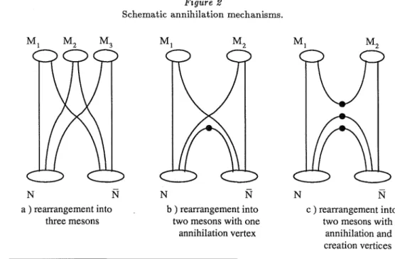
Table 2 Figure 2
Schematic annihilation mechanisms.
N c ) rearrangement into
two mesons with annihilation and creation vertices N
N b ) rearrangement into
two mesons with one annihilation vertex N N N a ) rearrangement into three mesons 39.0±0.8 8.7±0.5 98.8±0.03 Decay fractions for channels relevant in this thesis(%) Final products Decay channel '"('"( '"('"( p.+v p.+v P.-v P.-v '"('"( '"('"( 31To '"('"('"('"('"('"( 1T+ 1T-1TO p.+p.-'"('"(vv 1T+ 1T- p.+p.-vv 1T+ 1TO p.+'"('"(v 1T-1TO P.-'"('"(v 1T+ 1T-1TO p.+p.-'"('"(vv 1TO'"( '"('"('"( 769 135.0 139.6 139.6 548.8 782.6 Mass [MeV] w TJ Particle
The most common decays of the lightest mesons. The decays of special interest for this analysis are indicated (ref. [10]).
As already emphasized (Table 1) most pp annihilation channels involve the emission of pions. The charged pion has a mean life of 2.6 . lD-8 s while the mean life of the 1fo is
only 0.8 ·lD-16s. This means that the charged pions survive distances much longer than
the detector dimensions while the 1fo decays (mostly into 2 photons) in the target, a fact which has consequences for the detector design and data analysis.
Most naturally [9] one can consider a model where the three quarks and antiquarks in the proton and antiproton are rearranged into three mesons (see Figure 2a). The immediate conclusion of this model is that only three-body annihilations can occur. Thus the final state should contain three or more mesons due to further decay of the primary mesons. Furthermore, no strange mesons should appear and especially the production of<P
(S8)
must be suppressed. This simple model fits SO-90%
of the total experimental data(d.
Table 1). However, ~ 7%
of the annihilation channels do contain strange particles and there are at least 10%
two-body annihilations. For the understanding of the annihilation process in finer details a more refined model is needed, in particular to treat channels with more than one neutral particle in the final state. For obvious reasons such channels were hard to study with bubble chamber techniques.Some possible extensions to allow 2-body annihilation channels within the framework of the simple rearrangement model mentioned above are indicated in Figures 2b and 2c, but most theoretical works tend to avoid this question so far. The experimental information
on the yields of two-body annihilation channels is not only rare, but sometimes also contradictory when it exists. For instance for the annihilation channel pp -+ 1fo1fo the yield is reported by two different groups to be (0.014
±
0.003)%
and (0.048±
O.OlD)%,
respectively(d.
Table 1).Other annihilation models
Among several theoretical approaches to the understanding of the pp-system (for a review until 19S3 see Green [11] and references therein) the potential concept has been extensively used. The potential used has developed from a simple phenomenological nucleon-nucleon interaction potential to more refined potentials in which the quark nature of the associated particles is taken into account. A potential approach predicts only the appearance of two-body annihilation channels, but as shown in Table 1 many-body channels dominate the experimental data. This deficit of the model can, however, be cured to some extent by the construction of many-body channels from weakly coupled resonant two-body channels.
Baryonium and other exotic states
One striking feature of the nuclear potential models, observed first in 1956 [12,13] and developed by Shapiro [14], is that a nucleon-antinucleon force is necessarily strongly attractive. The corresponding deep potential well should thus contain several bound states as well as states in the continuum (Figure 3). Such states were named Baryonium in analogy with the name positronium(e+e-). The level energies and widths of
Baryo-Figure 3
Transformation from particle-particle to particle-antiparticle potentials for the strong interaction (below) and, for comparison the Coulomb interaction (above). The curves are schematic and the scales cannot be compared.
Electromagnetic interaction nium are, however, difficult to calculate because of the uncertain radial position of the
hard core and the interference with the annihilation process itself.
In the energy region 0 - 2G~V the standard QCD theory is not calculable in a
perturba-tion approach. However, there are some models, using simplificaperturba-tions, approximaperturba-tions or further assumptions to make the theory calculable, which agree reasonably well with the measured meson mass spectrum. Furthermore, qualitative arguments show that all possible mesons in this region are found. With" all possible" we mean qq systems where q is u, d or s. Other flavours are heavier and thus resulting in objects with masses larger
than 2 GeV. However, the question must be raised why there would not be meson-like
states of the type qqqq , or states with only gluons, often named Glueballs. This name is a little bit misleading since spherical Glueballs are not stable in QCD according to Robson [15J and a Glueball has to have a torus shape or more complicated geometry to be stable. Therefore, names like" Gluerings" have been suggested. There are sev-eral models predicting such objects. In many experiments such exotic states have been searched for.
Early experimental evidence of Baryonium
In 1974 an experiment by A. Caroll et al. [16J claimed the observation of a narrow
resonance in the pp and pd total cross section at 1932
±
2 MeV having a width ofr
=
9±
4 MeV. Similar results were also obtained by Chalupka et al. [17J. As nomesons were known or expected in this energy region these objects were interpreted as being something else than ordinary mesons. The interpretation chosen at this time
was a pp-state slightly above threshold,i.e. a Baryonium state in the continuum. These
measurements stimulated an intensive search also for bound Baryonium states, several experiments claimed evidence for structures in this energy region. The results of some
of these experiments are collected in Table 3 together with some results from older
experiments on pp annihilation and some results from observations ofe+ e- collisions.
All experiments claimed states below 1850 MeV and were suggested to be candidates
for eihter Baryonium or Glueballs. In Table4 suggestions are collected for Baryonium
states in the continuum. The present thesis is very much related to the search for bound
Baryonium states, i.e. narrow objects with a mass less than 2mp ,and was particularly
motivated by the findings of Pavlopoulos [18] et al.
E E (MeV) V r) (r) Strong interaction r E V=CV 'Y 'Y C
....
Y
E (MeV VCr) VCr) r _ _ _ Atomic states Theoretical backgroundA general review of Baryonium is presented in the theoretical work by Rossi and Veneziano [25J . The general impression from this and other surveys is that Baryo-nium should exist, though different authors may use the name in slightly different ways. Two basic theoretical approaches have been applied extensively to explain Barionium states; the nuclear potential model and the concept of four-quark states. Here, some nuclear potential results and one four-quark model, the MIT-bag model, will be briefly commented.
The nuclear potential model
The first work by Shapiro mentioned above
[141
and later reports [31] cover theessen-tial ideas for the possible existence of bound states and resonances in the NN-system.
-2.23
NN
NN
r
Resonant states (several) atomic states
Bound states
16
Table :1
Some experiments claiming objects with a mass below the 2mp threshold of pp annihilation at rest. All those "states" has been discussed as
possibly being Baryonium or Glueballs (but not necessarily by the original authors).
Mass Width "Name" Reaction ref Year
(MeV) (MeV) 1394±23 <46 pp-> 'Y+ Xo 18 1978 1423±10 45±20 E(1420) (3-4)pp-> 19 1967 1425±7 80±10 £(1440) pp(at rest)-> 20 1967 1640±50 220±100 8(1690) Jj'I!-> 'Y 211 21 1982 1646±11 <24 pp-> 'Y+ Xo 18 1978 1652±17 e+e--> XO 22 1979 1683±8 <21 pp-> 'Y+ XO 18 1978 1708±30 156±60 8(1690) e+ e- -> 'Y + K+K- 23 1982 1772±6 e+e- -> XO 22 1979 1794.5±1.4 pp-> p+X- 24 1971
Most later calculations are done after a similar scheme based on boson exchange mod-els. The general features of the one boson exchange potential model can be deduced in a systematic way [32], providing a specific coupling strength for each exchange parti-cle. This model or more elaborate ones, taking also two boson exchange into account, parametrized as the exchange of the hypothetical mesons 0'0 and 0'1, is fitted to low energyNNscattering data. In analogy with the transformation of thee- e- system into
an e+ e- system by charge conjugation theNN system can be transformed to an NN
system like pp by a G-parity transformation
(d.
Figure 3). Itthen turns out that theNNforce, which is repulsive with the exeception of the small attractive well which allows the only bound state
iD,
changes to a strongly attractive force for a large part of its range, mainly due to the fact that the w-exchange is strongly attractive in theNNcase. The major problem with such an approach is that the hard core NN potential due to w-exchange is difficult to determine experimentally. Its G-parity transform which dom-inates theNNbehaviour is thus sensitive to the least known part of the NNpotential. In addition, the levels of possible bound or resonant states are pushed and broadened in an uncontrolled way by annihilation. Furthermore, the whole approach assuming point-like objects must be questioned, since it leads to predictions for effects on such small distances that the quark substructure of the nucleons should be taken into account. Some of the main features of the nuclear model are compared with the MIT-bag model (to be discussed below) and some other models in Table 5. In Figure 4 one of the potential calculations of level energies is compared to one of the MIT-bag calculations.1'7
Table
4
Some experiments claiming non-strange resonances above the 2mp threshold of pp annihilation at rest
Mass Width "Name" Reaction ref Year
(MeV) (MeV) 1932±2 9±4 S pp,pd cross section 17 1976 1935±3 16±11 pp cross section 16 1974 1935±1.0 2.8±3.0 pp cross section 26 1979 1937±2 21±10 pp cross section 27 1980 2190±5 85 T1 pp,pd cross section 28 1967 2192.7~~:~ 97.6~~:~ pp cross section 29 1973 2155±15 35±75 pp cross section 30 1977 2345±10 140 U1 pp,pd cross section 28 1967 2359.4~~:~ 169.4~V69 pp cross section 29 1973 2380±10 140 Uo pp cross section 28 1967
2345±15 135~~~o pp cross section 30 1977
The MIT-bag model for quarks and gluons
In the MIT-bag model the quarks and gluons are put in a spherical cavity of radius r.
The eigenstates are then found using a proper completely antisymmetric wave function. The masses of the states are obtained by minimizing with respect to r the quantity
E(r)
=
Eq + E v + Eo + Egwhere Eq is the quark kinetic energy, Ev is an energy contribution from the confining pressure, Eo is an estimate of the effects of zero-point fluctuations of fields in a confining sphere and Eg is the quark - gluon interaction. The only limitation from colour is that
the system is a colour singlet. In the MIT-bag model there is room for multiquark states ofthe (q)n(q)ffi (n+m> 3) type besides the usual qq-mesons and qqq-baryons. The most interesting case in this thesis is n = m
=
2, and the further discussion will be restricted to this case and n = m = 0,i.e. a state containing only gluons. Following Jaffe [39] the discussion about Baryonium-like states will be divided into two parts depending on the angular momentum and the internal geometrical composition of states.(i) S-wave qqqq states analogous to the usual S-wave mesons and baryons. An S-wave
Table 5 Figure-4
Low-lying non-strange Baryonium masses according to different models A comparison of different models (from reference [25]). All models are not discussed in
this thesis. Further references to these models and theories are: for the Colour chemistry models [35] and for the Topological bootstrap theory [36]. The references in the table (54,55) are given as references [37,38] respectively in this thesis.
Compari\on among various approaches10baryonium phY;K:<;
hlLis!h~angular momentum of theNNsystem.
(hI/i..the angular momentum of the (qqHqq) system.
understood within the model. The major contribution to the mass of the states comes in this case from the kinetic energy of the quarks and antiquarks. Thus the model predicts, in first approximation, a ratio 2:3:4 ~ 700:1100:1500 MeV for the masses of qq (mesons), qqq (baryons) and qqqq ("Baryonium") respectivly. This would possibly be an explanation for the absence of exotic states in the low mass region. Jaffe [39] has associated four-quark states of this type with the mesons £(700), S* (980), a(980) and II;(?)*. Other authors have proposed to associate such states with bumps seen in e+e- annihilation in the mass region 3.6 - 4.4 GeV [40]. However, states of this type also have a large width into mesonic channels and are therefore not Baryonium-like states with the definition usually chosen which require Baryonium to have relatively long half-life.
Baryonium properlic\ Spectrum Trajectory parameters Assignemenls Ismpin G·parily Coupling to mesonic channels (ann.) Coupling loNN channch (sealt.) CandiJales lor narrow width slates oeDimpired duallnpologit.-al picture
Baryonium ..tale'> olher than Ml(qqqq): M!(qq) and
M~(noq's)
Mi:c;ing hetween exchange degenerate trajectories
Computed via duality from Ihe mulliperipheral structure of the cro'ised channel
No specific assignemenl allempted Problems with high mas" narrow stales Degeneracy
Suppressed byJOZI
Lack. of detailed calculations
Allowed
High spin states near threshold.
M1 andMlJ
Nuclearph~iC'\
approach
NoEXD
J=Istates c!u'itcr ncar
threshold and have lowL{~)
J-=0states more
deeply bound
Difficult. but many experiments need confirmation
Nodegeneracy
Suppressed by the wa\'e function being small in the annihilation region
Allowed
Bound states near threshold
Resonances withJ-=fl
MIT-bag model
linearEXDtrajectories for
/(hl>I
No mixing effects generally considered
Slopes and intercepts computed in tcrms of parameters of the model
Room for S,T. Uresonances
and for those of ref.{54!
Degeneracy
Suppressedby centrifugal
barrier.
Lack.ofdetailed calculations
Allowed
High spin states near threshold or states with exotic internal colour configuration
('olour chcmi\lrv
model Two kinds of states' T· and M-baryoniJ
LinearEXDtrajccloric~
Ilht>!
Mixing with normal
trajectories allowsfnr
M·haryonium productit'n Same slopes as in MIT-hag
model.T· and M-har)'onmm
intercepts from the assignment of the T-l.IS (leV and the 2.95 GeV states respectively
S. T. U resonances and thtl...e
of ref.(541 are T-har)'onia
Narrow high ma..s ..tale.. are M·baryonia Degeneracy Small splitting of G-parity doublets for M-haf)'llOium Suppressed by centrifuj:!.al barrier. Problem.. with low M·haryonia in specific non· relativistic quark model calculations Allowed for T·baryonium Forbidden for M-haryonium
M·haryonium and otherslate~
with e,;otic internal({"110m confi~urations.
S is a T·haryonium narrow because near threshold
Ttlpi'lncical l'l\}{lhlrap
Only the qqQq kind
of harynniumslate~
linear EXD Irajce!t1ric\III
Ix-(('mputed"elfcomi~lenll\'
in the '·phm,u rnlill\lJap" ,lrPTlI'(lmallnn (sec for imlancc reLI:;:,])
Nospecificas.~ignmcng
allemplcd.
Ptmi~lepwhkm\ with high
srin hif!.h rna\\ narrow~tale\
Dcgeneracy Ttlpoln~iGlllylnrhiddcn ailowcsinrdl'r Allowed Low angular momentum.lowe~t
ma~sslates.. Best
candidates: states under threshold Mass (GeV) 2
o
1=1 Nuclear potential [33) -1=1 MIT-bag model [34) 3 different colour bindings are indicated in the plotRecoil energy for a'Yfrom an imagined process pp---7'Y + Baryonium (MeV)
o
100 200 300 400 500 600 700 800 900 938.28this table
(5
comp diff models) is not yet ready (ii) HighP.
(angular momentum) qq (diquark) - qq (diquark) states corresponding toelongated bag structures. The coupling to mesonic states is supposed to be sup-pressed by centrifugal barrier effects. A motion which possesses a non-zero angular momentum is plausible to result in an elongated object. Ifthere are two quarks in one end of this structure and two antiquarks in the other, one can assume that they are kept apart by a centrifugal force and thus the coupling to mesons are reduced since it is not possible to form a colour singlet from qq or qq.Itseems reasonable to
* This work was done when these "mesons" where still " alive" . They are not listed in the 1984 version of reference 10.
20 21
Glueballs
One distinctive feature of the MIT-bag model is that also a state consisting of only gluons must have a mass [42], a prediction which is not a priori true for other models. A naIve MIT-bag model gives a mass of 960 MeV for the lowest glueball state. However, more realistic calculations increase this mass to above 1300 MeV. Some MIT-calculations on masses for glueballs are collected in Figure 5.
assume that it is the colour flux lines that keep the system together while the angular momentum provides a centrifugal barrier that prevents the quarks and antiquarks to combine to ordinary mesons. Using the assumption that string-like hadrons are tubes of colour flux lines which terminate on colour charges at the ends K. Johnson [41] found that the firstnarrow state, with spin 2, has a mass about 1.6 GeV. The bag model also predicts that states of high spin (high mass) should be more narrow. States of this type could be candidates for Baryonium states.
Mass (GeV)
2
Figure 5
Low lying Glueball masses according to MIT-bag models and Lattice theories
Recoil energy for a'Yfrom an imagined process pp--4'Y+ Glueball (MeV)
o
100 200 300 400 500 600 700 800the use of the lattice gauge concept. These calculations emerged from attempts to solve basic problems with QCD but has also resulted in estimates of glueball masses which gave similar results as the bag model. Unfortunately, the masses of the bosons and mesons are still difficult to calculate.
Quantum chromo dynamics (QCD), as all quantized field theories, has to be regularized and renormalized in order to give results which can be compared with experimental data. Generally, this is accomplished with a perturbative expansion, but in QCD there are problems which are not amenable to a perturbative treatment. This problem is not unique to QCD, but the availability of nonperturbative methods of analysis is particu-larly important, since the calculation of mass spectra hinges on them.
In order to solve these problems, Wilson proposed [47] in 1974 a formulation of QCD to provide a nonperturbative regularization, which has led to the very important result of proving confinement, as well as to estimations of glueball masses. The theory is defined on a hypercubical lattice in Euclidian space-time with a spacing a. Matter fields are only defined at the lattice points, but the gauge dynamical variables are finite group
elementsU~ associated with links, from x to x
+
[La, on the lattice. There is an actionS consisting of Sg
+
Sm where Sg is the gauge field action and and Sm is the actionfrom the matter fields. Sg is built up from terms depending on colour exchange in each
lattice point. In the continuum limit a -+ 0 this formalism is able to regularize the theory with the proper normalization. Numerical "experiments" show that a lattice spacing of
i':::i0.11 fm or less is enough to obtain stable results which is reasonable since the typical
scale for hadronic phenomena is 1 fm.
Several authors [45,46] have calculated the mass for glueballs within the framework of lattice theories. However, the technical (computer resource) problems are substantial. The results from different attempts are slowly converging (sometimes with a scale-factor) and some results are given in Figure 5. A comparison with the theoretical estimates of the masses from bag models is also done.
Conclusion
Bag models Lattice theory
o
Naive [43] Skagerstam [44] Berg [45] Ishikawa [46]
900
938.28
There exists several models predicting new exotic states in the0-2GeV region, but they
all suffer from lack of experimental data, since they contain parameters which have to be fixed by experiments. From the experimental point of view there are a number of claims that new states have been found. However, some of these claims suffer from poor statistics and others are questioned by new experiments. The work described in this thesis was to a great extent inspired by the fact, that it should be possible to reach four-quark states (qq-qq) as well as Glueballs in the annihilation of pp at rest and it
might be possibie that such states (XO
) are populated in the two-body process pp-+"tXo,
where the energies of the "t-rays should fall in the energy region 0-1 GeV, which can be studied with NaI(T£)-detectors at a reasonable cost.
Lattice QCD and glueballs
For a long time the use of the bag models was the only method to make reasonable numerical estimates of masses of particles, as it is not known how to make calculations of many observables with basic QCD (see below). However, recently there are new calculations on glueball masses done with a new approach to the QCD problems, namely
CHAPTER 2
EXPER~ENTALSETUP
"It is a capital mistake to theorize before one has data."
Sir ARTHUR CONAN DOYLE, Scandal in Bohemia
Requirements on the experimental equipment
As emphasized in the preceding section the main aim of the work presented in this thesis was to search for Baryonium states and for rare two-body channels where one or both particles decay by gamma-emission. Thus, the main experimental device needed was a gamma detector with good efficiency and resolution. Studies of the pp-system at rest means that the highest available momentum is equal to the proton mass. Thus the detector had to cover a range up to 1 GeV. The device chosen was a big modular NaI(Tl) detector described in detail below and in Paper I.
Furthermore, it is desirable to determine the multiplicity of the pions since the decay of Baryonium could be dominated by one channel and thus a window on the multiplicity spectrum could help to reduce the background. Since the dominant neutral particle is the 7fo which decays mainly to two "I-rays
(cf.
Table 2) it is also desirable to have two "I-detectors operating in coincidence mode. The ideal detector is one having 47f solid angle, including a magnetic spectrometer for the charged 7f and having almost no mass acting as a secondary source of radiation, could not be constructed nor for technical neither for economic reasons. Furthermore, since the experiment had the character of a pilot experiment for further studies, the detector had to be simple and a poor solid angle had to be accepted. This simple equipment offers still some experimental possibilities but also some obvious experimental difficulties.Below some experimentally important remarks are made before the final set-up is de-scribed.
• Neutral decay products
One objective of the experiment was to study poorly known neutral pp annihilation channels. All the neutral particles, to be considered, decay on a time scale which makes it difficult to measure their energy before they have decayed. The final decay products are usually two or several "I-rays which results in a continuous spectrum with an approximately exponential fall towards higher "I-energies. However, both 7fo and1]
(and to some extent
w)
have interesting decay properties which makes it possible to study monochromatic particles by measuring only one of its decay "(-rays (see below).• Two-body annihilation channels
. Experimen~ally ~wo-bodyannihilation channels playa special role, since the system
IS we~l deter~med If one of the two decay particles is detected. This fact permits
experIments wIth much less costly equipment than when simultaneously several particles have to be detected for the reconstruction of a certain event.
• Decay kinematics
In appendix A the kinematics relevant for this thesis is presented in greater detail. One central observation is that one can detect monoenergetic particles decaying into two "I-rays by measuring only one of the decay "I-rays and thus measure neutral two-body channels with one single "I-detector. This is due to the fact that the two decay "I-rays form a uniform distribution, with a maximum (and minimum) value depending only on the velocity of the decaying particle.
• Target
For several reasons we have used a liquid Hz target:
(i) One obtains different results from annihilation in a gas target and a liquid target. This is due to the fact that annihilation occurs from different initial states. In a gas target the annihilation occurs predominantly from a P-wave whereas in a liquid target Stark-mixing is shaking the system down to an
S-wav~
state before annihilation takes place. As the 7fo7fo channel is restricted to come from P-wave its branching ratio is dramatically different in a gas and a liquid target.(ii).
Th~poor quality of the p-sources (before LEAR) and the big momentum spread ImplIes that one must have a big enough stopping power in the target region. This is difficult with a gas target.(iii). The pp ~snot in a well defined initial isospin state. However, a neutron target
IS not feasIble and for a heavy nuclide the Fermi motion is distorting the relevant part of the spectrum.
For the Baryonium search (see above) a He target was also used. The experimental equipment
As emphasized above the purpose of the experiment was to study the proton-antiproton annihilation at rest resulting in "I
+
any other particle(s), or (7fo or 11)+
any other particle. As is well known(cf.
Table 3) the 7fo and sometimes the 11 decay into two "I-rays. The fact that studies of these particles in two-body channels can be done by measuring accurately only one photon means that one good NaI(Tl) "I-calorimeter was needed. A second NaI(Tl)-calorimeter was used to study coincidences. However the coincidence count rate was very low and this detector combination served only as a~ilot
experiment for later studies at LEAR.In addition a good p-beam with a beam telescope was needed in order to provide a trigger and separate the antiprotons from other particles in the beam in particular negative pions. The experiment included also multiplicity counters for both "I-rays
24 25
and charged particles. Below the experimental set-up is described item by item. The schematic layout can be seen in Figure 7.
The antiproton beam
As a source for p's the electrostatically separated so-called K23 beam at the CERN
proton synchrotron (PS) was used. The beam elements together with its optical equiv-alent is shown in Figure 6. The optimum efficiency was found at a beam momentum of 600 MeV/c in an earlier experiment [48] using the same beam line. At this beam momentum the beam was fine-tuned several times a day to optimize the stop rate. A maximum stop rate of~ 250 p's per machine burst was obtained. The same beam line was used in both the 1979 and the 1980 runs.
Figure 6
The beamK23 and its optical equivalent.
The symbols stands for, PT
=
Production target, Q=
Quadrupole magnets, B=
Bending magnets, SM=
correcting magnets to the Separator S, AP=
momentum slits, BS=
Beam stopper, AM=
mass slits and FT=
Target.The antiprotons are produced by letting the proton beam of the PS hit an internal tungsten target. The particles around a given momentum (in our case 600 MeV/c) are collected with a 6.p/p of 1
%
into a total acceptance of 8.7 msterad. This beam of particles is focussed and bent into an electrostatic separator. After passing the momentum defining slit (6.P) the beam is again focussed and passing a mass slit (6.m). Finally, the beam is bent into the experimental area and focussed. However after all this beam manipulation the beam still contains all the long-lived negative particles with the same momentum produced in the production target.The beam telescope
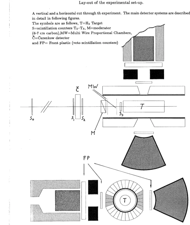
In order to distinguish between p from K-, 1r- and e- with the same momentum, a beam telescope was constructed, which consisted of four scintillation counters (To, TI , T2 , T3 ) and one 6erenkov detector (6). The lay-out is shown in Figures 6 and
7. Between the counter T2 and the multi-wire proportional chambers (MWPC) (see
Figure 7) there were placed carbon plates (6-7 cm) to degrade the beam in order to obtain the maximum of the stopping distribution at the center of the target.
The counter combination To - TI-T2 was used in the time-of-flight mode, and the
6erenkov counter discriminated at
/3
=
0.67. From this we could define two triggers, one for p and one for 1r- as follows- C _
T~- 6 -
Tt
=
(To - (TI - T2 )) time=p = (To - (TI - T2 )) time=".-T(p) T(".- )(Here
C
indicates that the 6 is in anti-coincidence mode, - coincidence and - (minus) a delayed coincidence. The index h ort
refers to the discriminator level which is set high for p and at just above noise threshold for 1r-).The time separation between p and 1r- was nominally 21.6 ns. The first trigger was also used as a p stop trigger. The separation power is shown in Table 6. The counter T3 placed just in front of thetarget defined a beam size which was smaller than the target. In order to keep the annihilation process within a reasonably small region, liquid hydrogen (helium) was used which enabled the target to be sufficiently thick to stop p within the target after
~ 15 cm. A target container with a cooling system was provided by the CERN target group [49] for each data-taking period. The target used in 1979 could also be used for helium and thus data for the process pHe --t"f
+
any other particles (Paper IV) wereconsequently produced only in the 1979 run. The possibility to tune the beam to both 1r- and e- was also used for calibration purposes.
VerticaL SM SM
eb~1!H8tgeee
~li
~
I
0. Q 0. B S.6.P BS 0. Q o..6.M B 0. 0. Q ,PT
FT
lilll
The "f - ray calorimeters
For the main part of the experiment, two different NaI(T£)-calorimeters were used. The so-called SECTOR, which was by far superior for E"I
::?:
100 MeV, was a modular (54 units) detector in a single housing covering 1/13 of 41r. In addition a 12" X10" cylindrical mono-crystalline NaI(T£) was used for the construction of 1r0 andTJ energy spectra (Paper V). The 1r0 and TJ spectra so obtained were merelly used for tests fora later experiment at LEAR (see Appendix D) and thus the performance of the 12" NaI(T£)-detector was less important.
Table 6 Figure 7
Lay-out of the experimental set-up. The beam telescope perfomance.
With a trigger which required only To T1 and T2 in coincidance a ratio of~ 1 for 7r-
If)
was obtained. Then by using the beam telescope we can gain the factors given below. It should be noted that although the trigger is virtually free from unwanted particles
(7r-
If)
~ 10-4 )after this telescope, secondary particles are also produced in the target.•
•
FP
M
c
\ /
A vertical and a horizontal cut through th experiment. The main detector systems are described in detail in following figures.
The symbols are as follows, T=H2 Target
S=scintillation counters To-Ts ,M=moderator
(6-7em carbon),MW=Multi Wire Proportional Chambers
C=Cerenkow detector '
and FP= Front plastic (veto scintillation counters)
>5
>
12>
175 gain factorThe SECTOR-detector was the main component of the experimental set-up and Paper I is devoted to describing its development and performance. Itwas the prototype of what became known as the Crystal Ball at SLAC [50]. The layout is shown in the following Figure 8 as well as in addition to several relevant figures in Paper 1.
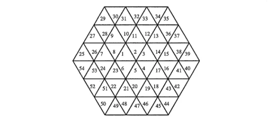
The SECTOR-detector* was built from 54 NaI(Tl) modules. All modules were simi-lar in shape but had for geometrical reasons differences in dimension of up to 12
%.
Each module was a truncated equilateral triangular pyramid (b ~ 13.5 cm at the wide base, h ~ 39 cm) of polycrystalline NaI(Tl)and was wrapped in white paper and in aluminized mylar for optical separation. Through a hole with a diameter of 50 mm at the outer triangular surface an air light-guide was fitted towards the glass window of the aluminium housing. A photomultiplier tubet was connected to each module by a second air light-guide into which light could also be injected from the light pulser (see below)**. The multipliers were magnetically shielded by 1 mm of It-metal and a housing of ~ 5 rom iron. The specificationstt
were tested individually for each module before packing into the common housing. All modules met the resolution requirement. Nine modules did not fully meet. the uniformity requirements and were therefore placed in the outer ring of the assembly (No. 25-54 in Figure 9) where less energy was accepted in each event and thus the performance was less critical. Figure 10 shows the performance of a typical module.As mentioned all the 54 individually wrapped modules were closely packed in a sealed * Manufactured by Harshaw Chemical Co., Solon, Ohio, USA.
t The PM's were SRC L50BOI or KTC XP2202B, which are semi-fast, 1>50 rom, 10 stage tubes
** These two air light-guides were the main reason for the relatively poor light output of the modules, 7
%
of a 2" X2" cylindrical NaI(Tl) placed directly on the tube which however, was acceptable for the energy range used.tt
See Paper I for details about the specifications. The SECTOR-detectorImprovement in the intensity ratio7r-
If)
T~ in coincidencealso
C
in anti-coincidence28
Figure 8
THE SECTOR
Schematic picture of the SECTOR-detector set-up. Only the modules are shown.
Technical details and specification can be found m PaperI.
p-beam
single aluminium housing. The stacking was done so that the arrangement cut out a
honeycomb from a hollow sphere with an inner radius of25 cm and an outer radius of
>::; 64 cm. The honeycomb-shaped projection can also be seen as three rings with 6, 18
and 30 modules in each (see Figure 18in chapter 4).
To discriminate charged particles from neutrals entering the "I-ray detector there was a thick scintillation plastic veto-counter between the target and the detector (see Figure 7). Furthermore, in all places where the mechanics and support allowed it, the part close to the target was covered by four plastic counters to veto charged particles entering from other sources than the main interaction region.
All PM's for the SECTOR itself and surrounding plastic counters were fed with high-voltage (HV) from individual channels. Once the calibration was done this HV was kept constant for each data taking-period, and any drift in the calibration was taken care of
29
Figure 9
Projection of the SECTOR. You stand in target and look on the SECTOR.
in the off-line analysis (see below).
In the 1979 run a negative HV was used. This had the drawback that irrecoverable
gain losses occurred (up to several
%
in one day). Thus the HV voltage was changed topositive for the1980data taking, which however had the drawback of causing non-linear
response for high energy inputs. The different PM bases are shown in Figure 11. Each PM was read out individually in two different lines in order to have both a large dynamic range and still keep a good precision in the low energy range where most modules have some energy deposit due to escapes from the module actually hit. Each
line fed an 11 bit ADC (LeCroy 2249 W). The ranges were set to>::; 0-1 GeV for the
high channel and0-100MeV for the low channel.
The light pulser of the SECTOR
In order to monitor and control the stability of the SECTOR-detector, a light pulser was
developed. The construction used is schematically described in Figure 12. The pulser
consisted of a light source, a light attenuator, a light diffuser, a distribution system, and a reference module with a radioactive source. The set-up was constructed in a modular way so that the main unit, the light diffuser box with a filter wheel containing six filters, and its remotely controllable electronics also served as a holder for the light source tower
and electronics. The reference module (a 2" x 2" NaI(T£) crystal and a 22Na source)
were placed in a lead' shield in the same thermally shielded box as the SECTOR itself.
The light pulse was produced by a xenon flash tube of the type FX 280*. This pulse
was shaped so that it resembled the pulse from the NaI(T£) modules. The intensity
Light output Arbitrary units
Figure 10
Performance of one typical (bad) module
Figure 11
Analog electronic schemes used for the SECTOR-detector bases in a) 1979 and b) 1980.
2
..
.
.
..
....
.
.
....
..
.
..
.. .
L 50 8 01 - 4 OR X P 22028 10K ... -1. kV HV~'-L.~~~~~~~"""""""~-4*'
561< J9K68K68r,68K 68K61l<&lK 68K 68K lOOK lSOKLRS 22l.9W
BEAM TRIGGER
X 54
L50801 -4 OR XP 22028 LRS 22L9W
could be adjusted continuously so that the light output after filter attenuation covered a range corresponding to 20-1000 MeV. But, once set, it was kept constant during the run.
Relative light output about 8 o'clock in the morning for module 30 illustrating the difficulties with gain stability using a negative PM high-voltage. 56 K J9K 6SK 68K 68K68X 68K Sfl< 68X &lK lOOK 150K 68 K 101'1101'1101'1 X54 HI Lo BEAM TRIGGER @t HV ... +,..4kV K Ace I 01 02 OJ DL 05 06 07 D8 09 010
T
11'1 11'1 11'1 11'1 tan101'1 SOn 501'11001'1 lOOn
I I J..GROUND OF PH BASE -L GROUND OF ElECTRONICS 60 Days 50 40 30 20 10
After attenuation the light was diffused in the diffusion box. Then it was distributed by 56 fiber light guides* each one of them with a diameter of 1 mm and a length of 2m. 54 of these fibers were connected went to their respective modules via a small hole in the second air light guide, one fiber was led to the reference crystal, and finally one fiber led to a special PM serving as a light pulser trigger. The possibility to check the LP against the 1.27 MeV line of 22Na showed that running the LP continuously with 5 Hz deteriorated the light output from the flash bulb by ~ 1
%
per week. A resolution of 2-4%
was obtained for selected flash bulbs. The LP was also used to check the linearity of the electronics and read-out system of the modules up to an energy range corresponding to 1 GeV.The cylindrical detector is described in reference [51] and in Figure 13. The NaI(T£)-crystal (12" X
cP
10" cylindrical) was surrounded by thick scintillation counters to en-able electronic collimation. The i-rays were further collimated by a lead collimator(cPinner
12cmX12cm deep). In front of the crystal there was one thick and one thinner scintillation veto counter to discriminate between charged particles and i-rays entering the detector. The collimation had to be weak in order to maintain a large solid angle for the coincidence experiment.Multiplicity counters 12" NaI(T£)
The second calorimeter was the same detector as the one used by the collaboration in an earlier experiment [18] on pp ----4 i
+
anything. In our work, however, it was onlyused for the coincidence analysis where the performance was less critical.
* Manufactured by Fiberoptik-Heim AG, CH 8707 Uetikon am See, Zurich, Switzer-land.
With the aim of reducing the background and identifying the decay of a possible exotic state, a set of multiplicity counters covering a solid angle of about 80% was constructed. This set of detectors are in the text below named the TONNE (inner, outer) from the German word for barrel. However in the quantitative analysis the requirement of identifying the final state of a decay channel reduced the statistics too much because of the pooroverall efficiency, and thus the information from the TONNE detectors was not of much use in the final analysis. The detectors are shown in Figures 14 and 15.
32
Figure 12
The lightpulser of the SECTOR (from paper I)
The light pulser(schematic). Not shown are the motor and the encoder for the diaphragm, and an additional retractable filter betwen the diaphram and the filter wheel.
33
Figure 13
The 12" NaI(Tf)-detector
Acut through the cylindrical12"by10" NaI(T£)detector. The crystal volumeXis surrounded by thick plastic scintillator (MP).In front of the detector there is two front plastic (FP) charge veto detectors and a lead collimator (Pb).
I I I I I I I I I I ~ 10em ~~-BLACK BOX
--
f----TRIGGER ELECTRONICS ~ FY - -I--BASE 507F f o l -I--XENON FLASH TUBE
56 LIGHT FIBERS ( FILTER WHEEL
r'
LENS MOTOR + + ENCODERI DIAPHRAGM I / / / / / / / / / / / / / / '/ / / / / /--'v' / / / / / / / / / / , / / / / /; I
\\
1
;,
I
I;
FILTER FILTER WHEEL
r/
/ FRONT END OF ~ ~ --WHITE DIFFUSER
I
LIGHT FIBERS 1/ / (RANDOMIZED) / /, / / / / / / / / / / / / / / / / // / / / / / / / / / / / / / / / // / / // // / / / / TO PM's) Figure 14Acut through the TONNE multiplicity counter
The inner TONNE consists of30plastic (IP) scintillator strips inside and an aluminum and iron cylinder (B). The outer TONNE consists of lead (Pb) plastic (Sc) scintillator sandwich with tungsten (W) walls.
The inner TONNE-detector was constructed to measure the charged particle multiplicity and consisted of 30 scintillator strips, each one1 m long and 1 cm thick, arranged in a cylindrical shape with a diameter of 30 cm. They were kept in position from the outside by an aluminium cylinder. From the inside they were supported by the slightly wedged shape of the slabs and by a black paper cylinder, which also served as protection for an aluminized mylar wrapping applied for the optical separation of each module. Each detector strip was coupled individually to a photomultiplier (PM). The signals were amplified and the threshold was set for optimizing the efficiency of minimum ionizing particles. The signals from all 30 strips were read out by two 16 bit pattern units in CAMAC.
The outer TONNE-detector was constructed to measure the photon multiplicity, and was located outside the inner TONNE on a 0.7 cm thick iron cylinder. Itwas made of 60 identical modules, each one 0.5 m long and having an angular width of 12 degrees.
Figure 15
Schematic picture of the TONNE multiplicity counter
CHAPTER 3
CALIBRATION, DATA-TAKING, MONITORING
p
"Tant de bruit pour une omelette au lard."
JACQUES VALLE DES BARREAUX
"Much Ado About Nothing."
WILLIAM SHAKESPEARE
The modules were sandwiches of lead and scintillator plastic (see Figure15for details).
Each module was connected to a PM via a light guide and read out individually via a bit pattern unit in CAMAC. The thresholds were adjusted so that an isotropic count rate was obtained when a small carbon target was irradiated in the center of the TONNE.
Two holes were cut out in the2
x
3central modules on each side of the cylinder in orderto avoid any interaction with matter before the "(-rays reached the NaI(T£)-detectors (Figure 14 and 7).
Before data could be taken the equipment had to be tested and calibrated. The require-ment for the inter-calibration of the modules was that the energy calibration for any
module should not vary by more than ~ 10
%
from its nominal value. Once thiscali-bration was established it had to be monitored. However it was not corrected on-line. Instead any variation during data-taking was corrected off-line in conjunction with the final calibration (see next chapter). Furthermore, all equipment had to be monitored during the run so that any temporary malfunction of the equipment could be corrected for.
Calibration
Before the run there were three possibilities for calibration, a source calibration up to
a few MeV the use of an electron beam or the 129.4 MeV "(-rays produced from the
reaction
7f~P
--4 n+ "(.
None of these methods could however be used duringdata-taking without interrupting it, but a source calibration record was made every morning.
Finally, off-line after the run the upper edge of the "(-spectrum
(E
ma" = mp ) and theenergy of "(-rays originating from the reaction
pp--4 7fo
+
w orpO"""
"("(could be used for calibration. For the12" NaI(T£) crystal the calibration was somewhat
easier since it consisted of one big module and hence no inter-calibration had to be done. Furthermore, minimum ionizing particles due to high energy cosmic rays could be used
to check the stability of the 12" NaI(T£)system in contrast to the more complicated
SECTOR case. This cosmic ray calibration could be performed simultaneously with
interuptions done for the source-calibration of the SECTOR. The 2.38 MeV Compton
edge of 228Th was used for ·inter-calibration and absolute calibration of the SECTOR modules at low energies. The high voltage of the PM's was adjusted so that all modules
36
had the same gain after feeding the signal through the same amplifier. The same. procedure without any adjustment of the high voltage was also applied once early every morning to check the stability. This procedure was performed also inbetween beam periods to keep record of the stability of the equipment. For the 12" NaI(Tl)detector we used 228Th (E.)'=2.62 MeV) for calibration at low energies.
Before the final set-up the beam was tuned for electrons in order to check the energy calibration and the linearity by putting the detector in the target position. This check was limited by the precision in momentum to which the beam could be tuned (::::: 2
%).
In the 1979 run the non-linearities 'were negligible (from calibration points in the pp data and from the light pulser (LP) data) and no correction was neccesery. In the 1980 set-up a few modules became non-linear above 400 MeV. This deviation was still reflected in the resolution at high energies after correction. The response of the 12" NaI(Tl)detector was well-known from earlier experiments [18], and the detector was therefore not calibrated in the electron beam in this experiment.
The calibration described above was not sufficient for the experiment, where the energy of the "{-ray was distributed in several modules. Thus the calibration was important in the energy range where the shower properties are dominant. At an energy::::: 100 MeV three calibration points can be obtained by tuning the beam for 1r- (see Figure 18 in chapter 4). These were:
1r- P-+n"{ E')' = 129.4 [MeV]
1r-p-+n1r° E')'min = 54.9 [MeV]
E')'maz = 83.0 [MeV]
The beam was thus tuned to stopping 1r- before and after each pp data-taking period, and the 1r-p data were stored on magnetic tape and used in the final calibration, which was done off-line after each run period. The data were also used for calibration for the on-line data-taking monitoring program.
Stabilization
Once the calibration was established it had to be stable over a long period of time however with no possibility to control it in a direct way. In order to maintain the calibration, data were taken with the light-pulser source described above approximately once every 4 hours for a few minutes and stored on magnetic tape. A survey of these data and a comparison with the source data showed that the accuracy was much better for the LP data, and thus the source data were only used for a consistency control. This scan of the data from the light pulser showed very different features for the different run periods of 1979 and 1980. As a consequence, the high voltage supply of the photo-multipliers was changed between the runs. The modification thus made proved to be satisfactory and the 1980 LP data did not vary by more than ±1.2% for any module except for short periods which were anyhow disregarded in the data analysis for other reasons. Therefore it was decided after tests that no off-line correction were needed for the 1980 data and therfore the following procedure was only applied to the 1979 data.
37
The off-line calibration was done after the full run period so that all the information about the performance of the modules was known in advance. Therefore, after com-paring the LP-data and the source data the decision was taken not to further correct the 1980 data. After establishing a reference value, the LP data were fitted for each time interval with a second degree polynomial. This procedure gave an individual time-dependent expression for each module. The coefficients thus obtained were then introduced into the off-line analysis program "SECTOR".
Once it was known that the light-pulser data and the source data gave consistent results we could use the LP results alone since they were more accurate and more frequent. Finally, the light-pulser itself had to be stabilized in order to avoid additional errors from instabilities in the light bulb or gain shifts in the PM's and amplifiers. Thus a time-dependent coefficient for the reference valueAre!>defined as Are!= PSource(O)
j
PSource(t) where PSource(t) is the peak position at time t was applied to the data.
Data - taking system
The data-taking, the control of the experiment and the monitoring were all done with a PDP 11/34* computer. For interfacing between the computer and the electronics a standard CAMAC interface was used.
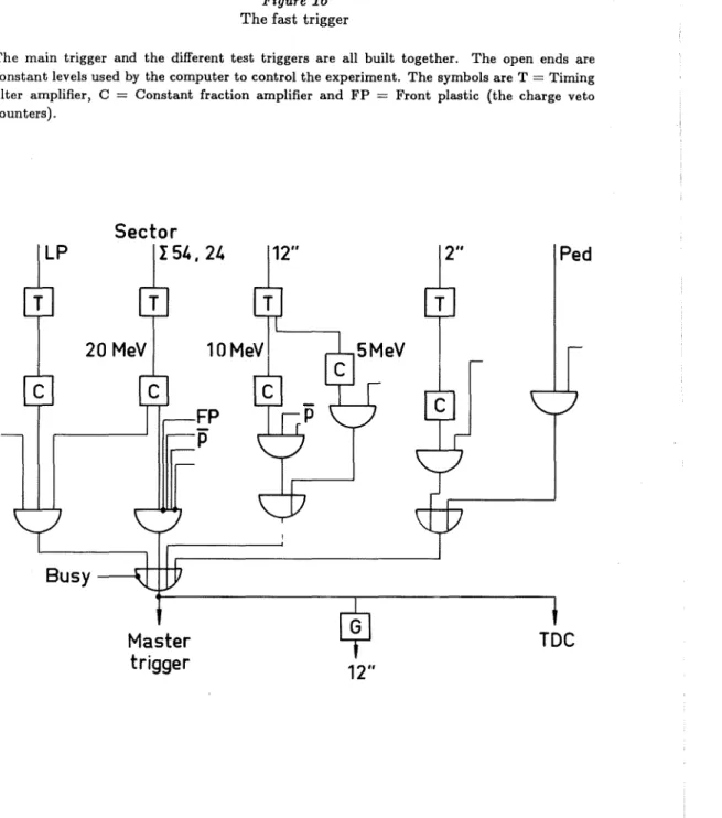
The fast trigger T was built from standard NIM units (see Figure 16). The master trigger was defined as
M =
T(Patop) •
s')'where s')' denotes that the inner 24 modules contained more than 10 MeV equivalent energy and no veto plastic scintilator was fired. This trigger opened a gate (700 ns) for the all ADC's of the " Sector" . After conversion the data were read into a buffer in the computer, together with the other relevant information. In order to take data for tests and calibration (e. g. LP-data), the computer could change the trigger by means of output registers in a well defined way. Only in the case of 1r- data the trigger had to be changed manually.
The data-taking program used was meanwhile developed by the CERNDDjOC group to be CERN's standard data-taking program for PDP's. As this program was not final at the set-up of the experiment a considerable time was invested in testing the program to secure data integrity.
Figure 16 The fast trigger
CHAPTER 4
ANALYSISThe main trigger and the different test triggers are all built together. The open ends are constant levels used by the computer to control the experiment. The symbols are T
=
Timing filter amplifier, C=
Constant fraction amplifier and FP=
Front plastic (the charge veto counters).,,, What are youdoing?" "Hunting," said Pooh. "Hunting what?"
"Tracking something," said Winnie-the-Pooh very mysteriously.
"Tracking what?" said Piglet, coming closer.
" That's just what I ask myself. I ask myself, What?" ,
A. A. MILNE, Winnie-the-Pooh
monoenergetic ')'-rays with 90 MeV < E')'< 938 MeV
monoenergetic 7TOrevealing themselves as box edges with E')'~ax < 933 MeV where beacause of statistical reasons only the high energy box edge (E')'~ax)can be observed.
1) Analysis of the singles ')'-ray inclusive spectra from pp annihilation at rest, where we were interested in:
The analysis consists of three parts.
The object of the analysis was the inclusive ')'-spectra from pp and pHe annihilation at rest. Ifthe annihilation at rest results in two particles they both have well defined energies depending on their masses only. On the other, when hand an annihilation at rest results in three or more particles, it gives rise to a continuous energy distribution. Thus, when one particle is produced together with a single ')'-ray the recoil of the particle is visible in the ')'-spectrum as a monoenergetic peale Also, if one particle is produced together with a1l'0 this can be seen in the ')'-spectrum, since the ')'-rays from
a monoenergetic 1l'0 decay in motion will be distributed as a "box" in the laboratory
frame. Details about the relevant kinematics for two-body annihilation are given in Appendix A.
Ped
TOC
12"
FP
P
Master
trigger
Sector
I 54.24
Busy
2) Analysis of the singles')' inclusive spectra from pHe annihilation at rest. This analysis is different from the search for monoenergetic ')'-rays in pp data. Here we studied in particular the region 50 <E')' < 500 MeV because of the presence of neutrons and Fermi motion of the nucleons.
3) Analysis of the coincidence spectra between the two detectors, the SECTOR and the 12" NaI(T£). Where we studied the 7TOandTJ spectra at low momenta. This