Technical report, March 2012
Network project 7.5 credits
Tunnel comparison between
Generic Routing Encapsulation
(GRE) and IP Security (IPSec)
Akinola Azeez Paul
Chong Zhang
2012-03-27
School of Information Science, Computer and Electrical
Engineering - Halmstad University
1
Table of Contents
Abstract ...4 1. Introduction ...5 2. Goals ...5 3. Security Recommendations ...63.1. Security for Networks ...6
3.1.1. Secure Physical Access to the Console ...6
3.1.2. Restricting Management Access Using Access Control List ...6
3.1.3. Firewall ...6
3.1.4. IPSEC/VPN ...7
3.1.5. Create a user profile for each user ...7
3.1.6. Update the operating system ...7
3.1.7. Educate the users ...7
4. Tunneling Technologies ...8
4.1. GRE tunneling ...8
4.1.2. Properties of GRE ...9
4.2. IPSec/VPN Tunnel ... 10
4.2.2. Security Services provided by IPSec ... 10
4.2.3. Modes of Communication ... 10
4.2.4. How to use IPSec/VPN ... 12
4.2.5. Components of IPSec/VPN ... 12
5.3. Wireshark ... 14
5.3.1. Purpose of Wireshark... 14
5.3.1. How to use Wireshark to catch network traffic. ... 15
5.4. Jperf ... 16
5.4.1. Components of Jperf ... 16
5.4.2. TCP Measurements ... 17
2
5.4.4. Useful Jperf Invocations ... 18
5.4.5. Using Jperf to generate high rate streams ... 18
6. Methodology ... 19
6.1 Networking Equipment ... 19
6.2 Implementation... 19
7. Results ... 20
7.1. Scenario 1 GRE ... 20
7.1.1. Network performance via Jperf (TCP) in Scenario 1 ... 22
7.1.2. Network performance via Jperf (UDP) in Scenario 1 ... 24
7.2. Scenario 2 IPSec ... 26
7.2.1. Network performance via Jperf (TCP) in Scenario 2 ... 28
7.2.2. Network performance via Jperf (UDP) in Scenario ... 30
7.3 Comparison between Scenario 1 and Scenario 2 ... 32
7.3.1. Jperf Results Table ... 32
7.3.2. Wireshark Results Table ... 33
8. Conclusion ... 34
3
List of Figures
Fig.1 GRE TunnelFig.2 VPN Tunnel Fig.3 IPsec Architecture Fig.4 Wireshark
Fig.5 Jperf Client and Server Fig.6 Jperf Example
Fig.7 GRE-Tunnel Topology
Fig.8 Packet data captured from Wireshark Fig.9 Scenario 1 Bandwidth (TCP)
Fig.10 Scenario 1 Bandwidth and Jitter (TCP) Fig.11 Scenario 1 Bandwidth (UDP)
Fig.12 Scenario 1 Bandwidth and Jitter (UDP) Fig.13 IPSec/VPN-Tunnel Topology
Fig.14 Encrypted packets captured from Wireshark Fig.15 Scenario 2 Bandwidth (TCP)
Fig.16 Scenario 2 Bandwidth and Jitter (TCP) Fig.17 Scenario 2 Bandwidth (UDP)
Fig.18 Scenario 2 Bandwidth and Jitter (UDP)
4
Abstract
Since the introduction of networks, they have been used amongst home users, companies and organizations and most damage on the network is due to inappropriate security configurations. To secure networks, a protocol suite can be used to encrypt and authenticate all IP packets of a session. Therefore, this report will include the advantages and possible solution of some techniques used to offer increased network security such as scalability and data confidentiality. Captures of traffic sent using the two security techniques, IPSec/VPN and GRE-Tunnel will be monitored. The objective behind this project is to configure a network with these two different tunneling techniques and compare the security and network performance. The report also describes the security problems encountered by networks such as the ignorance of network users, vulnerabilities and the security of the devices. IPSec is a standard security protocol solution for TCP/IP, and it provides security through authentication, encryption and data integrity. GRE encapsulates packets and create a logical hub-and spoke topology of virtual point-to-point connections. The Jperf-tool is used to measure network performance and show specific details while another tool, Wireshark is used to analyze the information captured during transmission of data sent using IPSEC and GRE. The comparison further finds that IPSec-tunnel technique makes data transfers very secure but causes network performance disadvantages in comparison to a GRE solution.
5
1. Introduction
Secure access technologies play many vital roles in computer networks around the globe. They are designed to minimize and reduce the risk of losing privacy and valuable information during communication via the Internet. Security is very important in a network. There are many attacks that could harm the network and if proper documentation and planning are not taken into consideration, the network could be easily compromised. Threats to any network arise from both external and internal entities such as unauthorized users (hackers), virus attacks and ignorance of users. For example, a person can leave the computer and expose it to unauthorized users [5].
The terms man-in-the-middle or hacker are sometimes used interchangeably. They make use of sophisticated software to collect data and break the security of a network. The United States FBI sometimes refers to the man-in-the-middle or hacker as criminals because they are involved in various crimes via the internet such as exploitation of valuable information, stealing of documents and accessing databases illegally [5], [14].
Goals
The main goal of the GRE and IPSec/VPN tunnel in our report are:
Compare the security strength between the two techniques over a specific network (from HQ to BR system).
Measure the network performance such as bandwidth, jitter delay, lost packets.
To document the solution offered by these security techniques and also describing the technologies and tools used to collect data.
6
2. Security Recommendations
3.1. Security for Networks
This paper describes some different network problems and technologies that can enforce efficient security policies on wired networks. The reality is that most new networks that are being implemented to have a diverse set of needs for security [14]. Security is all about protection, guiding and identifying the risk as well as understanding where it comes from, how it can be mitigated [13].
Every device in computer networking and communication requires a security policy. Hackers find it much easier to break into networks due to improper security management by users. Employees of different departments need to monitor integrity and secure access for data to perform their jobs; vendors and partners need to restrict access to certain applications, internet-only access to visitors and validation of guests or students required [14]. To avoid these problems, security measures must be implemented on networks to guard against unauthorized users from important resources. IPSEC, VPN, firewalls, secure management and physical access [2].
3.1.1. Secure Physical Access to the Console
The physical security of layer three switch or router's console port is a very important element. A malicious person may access the console port to recover or reset passport and configuration information. It secures the console by using security personnel, locking cables [14].
3.1.2. Restricting Management Access Using Access Control List
ACL is an effective way to manage and restrict remote access traffic in the prevention of unauthorized access and denial of service attack against a management interface. An ACL mechanism can also be used in conjunction with distance vector and link-state routing protocols [2], [13].
3.1.3. Firewall
The firewall consists of hardware and software, and the firewall provides security between private and public networks. The way to provide a secure gateway between
7
different internet service providers against external network attacks. It also helps by accessing the logs to check if the program is behaving abnormally and the logs determine suspicious user activity. A reputed firewall keeps hacking away from the network [5].
3.1.4. IPSEC/VPN
An IPSEC/VPN can be used to protect IP packets traveling from one location to another. The location could end clients, such as a PC, a printer, a small branch office, a large branch office and service provider. The combination of two different sides determines the type of VPN in use. IPSEC/VPN only protects the transport layer and user’s data. IPSEC cannot extend service to a date link layer. If a project data-link layer is needed, then some of the encryption mechanism is also needed. In real encryption, IPSec/VPN consists of these following features: confidentiality, integrity, authentication and anti-replay mechanisms [1] ,[3].
3.1.5. Create a user profile for each user
By avoiding using the administrator account all the time, install or remove network component’s software. A strong password of eight characters that contains at least three digits, and a special character make it tough for hackers or man-in-the-middle to break into a network [5].
3.1.6. Update the operating system
This helps to reduce the vulnerabilities as the developer identifies and patch and weaknesses in the operating system and also implement anti-malware on a network [5].
3.1.7. Educate the users
The training should include lessons such as scanning attachments, download files before opening them and logging off the computer if not used. Educating the users about possible threats and damage caused by ignorance are very important [5].
8
4. Tunneling Technologies
4.1. GRE tunneling
The GRE is a tunneling protocol that was originally developed by Cisco and transport multicast traffic and IPV6. It allows connectivity between remote areas if a network to communicate via a common network protocol and link independent of native network protocol or routing protocol of their interconnection. It provides virtual connections and static-IP address without hiding the information or data via network. For connecting a server to the internet, there is weak encrypting, and it doesn’t provide any authentication. The GRE is a protocol for other tunneling protocols such as MPPE/PPTP uses GRE to form the actual tunnel, but it has been generic tunneling through capacity and it also use for tunnels that carry IP and are carried by IP. Due to lack of good authentication, they are unsuitable for users’ tunnels, but it has excellent performance over the network. A GRE tunnel interface will come up once it configures properly, and it stays up as long as there is a valid tunnel source address. The destination IP address must also routeable, and the interface is down if the remote endpoint is unreachable. A tunnel is used when packets need to be sent from source to the destination, without being treated like IP packets by any intervening routers [8].
9
4.1.2. Properties of GRE
GRE is an OSI layer 3 tunneling protocol:
It creates a virtual point to point link to Cisco routers at the remote point over a network. It encapsulates a wide variety of protocol packet types inside the IP tunnel.
It uses the header to support any other OSI layer 3 protocols as payload (IP, apple talk). It creates a logical hub-and-spoke topology of virtual point to point connection.
It secures communication over an untreated network.
It encapsulates an arbitrary packet inside a transport protocol and it’s a Cisco multiprotocol carrier.
It is an architecture that is designed to provide the services necessary to implement any standard point to point links and configure a separate tunnel for each link [8].
10
4.2. IPSec/VPN Tunnel
It is a protocol that allows for it to manage different types of security and negotiate protocol. IPSec also included protocols for establishing mutual authentication between hosts at the beginning of the session and negotiation of cryptographic keys to be used during the session. It operates in the internet layer of the internet protocol suite. IPSec tunnel only transported what its configuration specified and make it considerably more complex to use than other tunnels. It has two modes, tunnel mode in which it provides its own tunnels and transportation mode in which provides encryption and authentication on tunnels created on network links [1],[12].
4.2.2. Security Services provided by IPSec
It prevents spying of data and information flow over the internet and illicit access to resources. It provides all the following security services:
Security protocol: AH, ESP, ESP + AH Encryption: DES, 3DES, AES Authentication: MD5, SHA-1 Protection: DH1, DH2, DH3 [3].
4.2.3. Modes of Communication
IPSec is an end-to-end security operation in the network layer communication by authenticating and encrypting each IP packet of a communication session.
Transport mode
The data transfer of the IP packet is usually encrypted and authenticated. The transport and application layers are always secured by hash. Transport mode is used for network-to-network communication. For example, it provides for end-to-end security from client to server, server to server, and client to the client.
Tunnel mode
In tunnel mode, the whole packet is encrypted and authenticated and then encapsulated into a new IP packet. It used to create a virtual private network for host-to-host
communication. For example, a secure remote access from client-to-gateway over the internet using layer two tunnel protocol secured by IPSec [1] , [8], [11].
11
Before ESP
Original IP header TCP Data
Transport Mode Original IP header
ESP header TCP Data ESP trailer ESP
authentication
Encrypted and Authenticated
Tunnel Mode New IP header
ESP header Original IP header
TCP Data ESP trailer ESP
Authentication Encrypted and Authenticated
12
4.2.4. How to use IPSec/VPN
The fig2 diagram below shows how IPSec protected all exchanges between various private networks separated by an untrusted network. It operates link-by-link orientation and protected devices with security gateways [1].
Establish end-to-end secure communication between the communication devices and require deploying IPSec on all devices[11].
It can be implemented in every device that uses the network and provides end-to-end or link-to-link security [11].
Fig.2 VPN Tunnel
4.2.5. Components of IPSec/VPN
Authentication Header (AH): The IP authentication header is used to provide integrity and protection, and data origin authentication against threats.
Encapsulating Security Payload provides a combination of security services, integrity, confidentiality, and authentication of data in a network environment. ESP can be applied to the IP authentication header or alone.
Internet Key Exchange (IKE) is a key management protocol that provides a strong security association to handle the negotiation of authentication algorithms, encryption algorithms and the key’s lifetime.
High security level is used with strong algorithms and in a network environment. Consequences: it implemented in every device that uses the network and transparently
13
Does not replace current security solutions, but provides additional properties [1] , [4] ,[11]. Fig.3 shows the IPSec architecture
14
5.3. Wireshark
Wireshark is basically designed to locate the cause of network problems, poor network performance and security-related issues. It is most widely-deployed network and packet analyzer. It helps to test the competency of network performance, troubleshoot and secure network (IP/TCP). It analyzes the network packet that was captured and displays the packet detail’s information. Wireshark includes a complex color-coding scheme. The lighter blue rows are UDP SNMP traffic, and the green rows signify HTTP traffic. It techniques, including writing traffic filters to simplify packet analysis and exporting data for use in other applications [6],[10].
5.3.1. Purpose of Wireshark
It helps to troubleshoot network problems. It is used to examine network security problems. It is used to debug protocol implementation.
It is also used to capture IP packet from the network interface. It is available for UNIX and Windows
15
Fig.4 Wireshark [10]
From the fig 4, Wireshark capture packets and allows the details to be examined by users. It can also capture packet or traffic from many different networks. Wireshark is open simulation software, and it’s released under the GNU. It can be installed on any computers without license key or fees. It is easy for users to add new protocols to Wireshark [6].
5.3.1. How to use Wireshark to catch network traffic.
As a network packet analyzer, it’s one of the most powerful tools used to take a security analyst in a network. It can be used in two ways either for good or for evil, as is the case with many security analyzers.
Good way: The user or administrator makes use of Wireshark as a valuable troubleshooting tool to measure the network security. It can be used to identify the specific type of attack in a network.
Evil way: someone with questionable ethics, it‘s a powerful software tool that enables anyone to view every packet or traffic that traverses the network [6], [10].
16
5.4. Jperf
Jperf is a benchmarking tool for determining TCP and UDP performance between 2 systems. It is used to measure maximum TCP bandwidth, allowing the tuning of various parameters and UDP. It is open-source software and run on various platforms such as Linux, UNIX and Windows. It is a modern tool for network performance measurement written in C++. Jperf can be used for comparison of wired networking equipment and technologies in an unbiased manner. It helped to have a fact of the quality of and network and use as a tool to measure the performance of a network interface, and it works as an on-demand client and server test [7], [9].
5.4.1. Components of Jperf
The test can be run on two different computers one as a server over a specified port (TCP5001 by default) and the other functions as a client. The binaries are the same and there is an option to have the role of client and server [7].
Client is the sender
Server is the receiver (discard server) Fig.5 Jperf Client and Server
17
5.4.2. TCP Measurements
To get full TCP performance the TCP window needs to be large enough to accommodate the bandwidth delay product.
The bandwidth is measured through TCP tests a. Measurement includes the endpoints. b. Sometimes called end-to-end tests. The Limits of what we can measure
a. TCP is a largely a black box.
Many things can limit TCP throughput a. Loss.
b. Congestion. c. Buffer Starvation. d. Out of order delivery.
From the fig. 6, Jperf is installed on a windows machine of the two endpoints. They were both on the same network environment. By default, the Jperf client connects to the serveron the TCP PORT 5001 and bandwidth displayed by Jperf is the bandwidth from the client to the server. The –d and –r Jperf client arguments measure the bi-directional bandwidths and UDP tests, uses the –u argument [7], [9].
5.4.3. UDP Measurements
UDP provides greater transparencies We can directly measure some additional facts:
a. Latency (response time) can be measured with the ping command. b. Jitter (latency variation) can be measured with a Jperf UDP test. c. Datagram losses can be measured with a Jperf UDP test.
18
5.4.4. Useful Jperf Invocations
The –w option for Jperf can be used to request a particular buffer size, and this set for both sender and receiver buffer size (the OS may be required to allow buffers of sufficient size).
The parallel transfers can be useful with the help of –p option. TCP and UDP Properties
a. –I n report the status for every n seconds b. –d do bidirectional test simultaneously
c. –r do bidirectional test one after another [7], [9].
5.4.5. Using Jperf to generate high rate streams
UDP doesn’t require a receiver A device such as switch and routers must have a good counter to measure network performance.
It turns out that UDP reception can be very a resource intensive resulting in drops at the NIC at high rates (8-9 Gb/s) [7],[9].
19
6. Methodology
This research narrates the current problems in a network, security strength between two tunnel technologies, and measurement of the network performances and provides a suggestion to cover the issues with the help of some practical implementations in a laboratory environment.
6.1 Networking Equipment
Our network equipment are three routers, two switches, 10base TX cables and two host systems. We also run the installation of open-source software such as Wireshark and Jperf 2.0 versions on our two host systems. Jperf is a benchmarking tool for determining TCP and UDP performance between two systems. We also use Wireshark for capturing packets over the network.
6.2 Implementation
Our aim is to carry-out two tests and take each measurement accordingly. We had two scenarios during our test in the lab, and first scenario is an implementation of GRE Tunnel in a network and the second scenario by implementing an IPSec /VPN tunnel in the network. After each scenario, we sent traffic (TCP and UDP). We used Wireshark to monitor the traffic and check for the security information between GRE and IPSec Tunnel in the network. Jperf is also used as a benchmarking tool to determine network performance between HQ and BR system. We were able to take the measurement of bandwidth and jitter delay, and they are presented in the Jperf table with the color red and blue (bandwidth is denoted by the color blue and Jitter is represented by the color red) in the results.
20
7. Results
7.1. Scenario 1 GRE
Fig.7 GRE-Tunnel Topology
The topology above represents the picture of scenario 1 in the implementation, and the cabling of the routers and switch and direct connection to the PC. The configuration all the interfaces with the IP address, set clockrate on the appropriate interfaces and issue the no shutdown command where it’s required. The EIGRP AS 1 is configured to remote the network between HQ, ISP, and BR to establish successful communication between HQ, ISP and BR.
The two open-source applications Jperf and Wireshark are run on the system. Jperf is installed on HQ and BR while Wireshark is installed on a special host connected to switch in between HQ and ISP. The GRE- Tunnel is implemented on the network to allow connectivity between remote areas of the network to establish communication in the network protocol and routing protocol of their interconnection. The two endpoints (HQ and BR) are configured with a tunnel interface address and also assigned source and tunnel destination address. The ISP represents the agency providing connectivity between the two endpoints.
The traffic is sent from the HQ to BR and with the help of Wireshark on the special host stand as a monitor and analyze agent of traffic sent from the endpoints. We discover that
21
GRE-tunnel is not encrypted, but the packet is encapsulated and this can be the danger to vital information sent over the network. The Wireshark details below a show that GRE-tunnel is not a strong encryption method to protect traffic over the internet because we can see the users detail and password Cisco from the result.
The Jperf on the two endpoints are used to measure network performance such as bandwidth, delay, jitter, and packet loss during communication in the network. Jperf component consists of server and client, and every client is the sender and server act as a receiver. The host who connected to HQ local IP address is configured into the Jperf client on a host who connected to the BR. In Jperf configuration server required no IP address, but the IP address is mandatory for clients to establish communication. The BR (PC) is configured as the client which is always the sender in Jperf environment and HQ (PC) represents to serve, which is the receiver. The Jperf test details in the result show the TCP and UDP measurement.
Fig.8 Packet data captured from Wireshark
Figure 8 shows that the password in cleartext, and we are able to confirm this after the telnet and sent traffics from (HQ) to (BR). We also issue the ping command to confirm connectivity across the local subnet between the endpoints. The above test shows the packets captured via Wireshark and the password was unencrypted.
22
7.1.1. Network performance via Jperf (TCP) in Scenario 1
Fig. 9 Scenario 1 Bandwidth (TCP) TCP(sender) [ID] Duration/ Interval (Second) Data Transfer (Kbytes) Bandwidth (Kbits/Sec) [1919] Sent state 0.0-1.0 16.0 131 [1919] Ack-state 0.0-13.1 96.0 59.0
The result above, Jperf shows a connection start at the bandwidth of 131kbites/Sec, as the advertised speed. The speed was substantially different at the validation point. Our tests vary from 1-2 second. A Client connecting to 192.168.10.5 and client uses TCP port 5001 by default with window size 8.00 Kbytes (default). From the fastethernet a packet is sent (TCP) from a client system to the server system. A Local system IP address of 192.168.11.5 at port 2155 connected with 192.168.10.5(Jperf) at port 5001. The traffic was sent once, and we are able to measure the interval, the rate at which the packet was transferred and the bandwidth. From the graph above it shows the communication started at the interval level 1-2 Sec. The connection falls down in interval 2 Sec at the transfer of 16.0 kbytes with bandwidth of 131kbits/Sec. It also sends another packet at
23
the interval 2.0-10.0 at the same transfer speed of 8.00 Kbytes and with a bandwidth of 65.5 Kbits/Sec at the interval, 0.0-13.2 second with transferred of 96.0kbytes, and a bandwidth of 59.8kbits/Sec to acknowledge the packet sent between the endpoints.
Fig. 10 Scenario 1 Bandwidth and Jitter (TCP) TCP(receiver) [ ID] Duration/ Interval (Second) Data Transfer (Kbytes) Bandwidth (Kbits/Sec) [1872] Listen state 0.0-2.0 8.61 70.6 [1872] Ack- state 0.0-13.1 96.0 60.0
From the tests above, the server is the receiver while the client is the sender in Jperf environment. The server was waiting for the packets sent by the client. It was about listening state by the TCP port 5001 default. The window size is 8. oo Kbyte by default. Server host (PC) was configured with the local ip address of 192.168.10.5 by default port number 5001 connected with a client PC ip address of 192.168.11.5 by port 2155. From the test, there was no connection established from an interval range of 0.0-1.0 Sec, server acknowledges packet transfer (TCP). From the client at the interval 1.0-12.0 Sec, and the result of the test was varied from 7.38-8.61 Kbytes and 55.5-65.5 Kbits/Sec. To
24
get full TCP performance the TCP window needs to be large enough to accommodate the bandwidth delay.
7.1.2. Network performance via Jperf (UDP) in Scenario 1
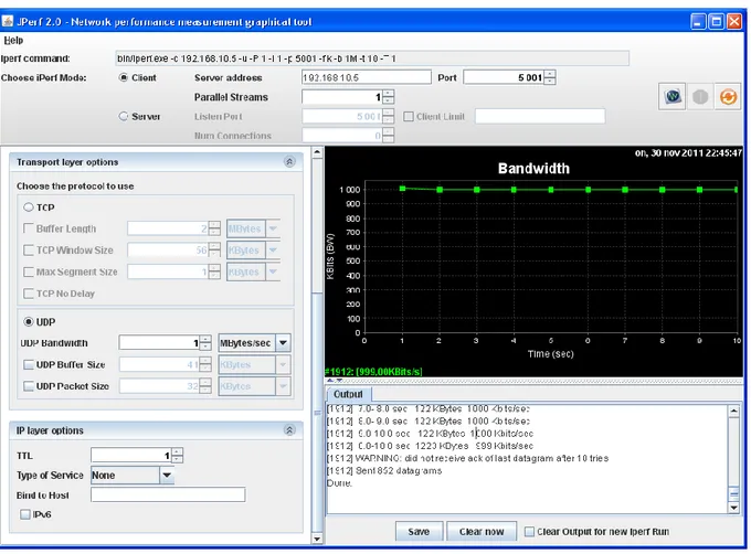
Fig. 11 Scenario 1 Bandwidth (UDP) UDP(sender) [ID] Duration (Second) Data Transfer (Kbytes) Bandwidth (Kbits/Sec) [1912] Sent state 0.0-1.0 123 1011 [1912] Ack- state 0.0-10.0 1223 999
The table above shows the result test for the traffic (UDP) sent from the client as the sender to the receiver server PC. This time traffic was sent twice to check and measure the accurate result run on the two endpoints. At this stage client connecting to 192.168.10.5 UDP Port 5001 sending 1470 byte datagram UDP butter size is 8.00 Kbyte as default. The local PC was manually configured with an ip address of 192.168.11.5 at port 2322 connected with 192.168.10.5 port 5001 at the interval range of 0.0-1.0 Sec and transfer packet at rate of 123kbytes with a total bandwidth of 1011kbits/Sec.
25
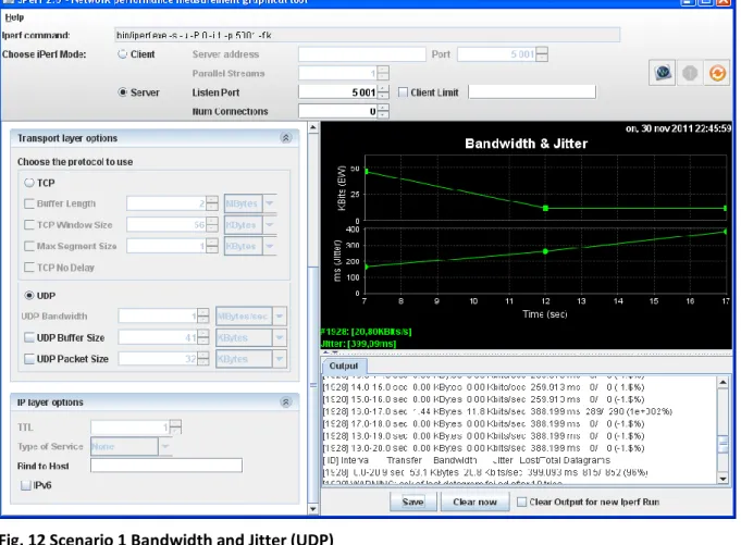
Fig. 12 Scenario 1 Bandwidth and Jitter (UDP) UDP(receiver) [ ID] Duration (Second) Data Transfer (Kbytes) Bandwidth (Kbits/Sec) Jitter(ms) Lost/total Datagram’s [1928] Listen state 0.0-1.0 7.18 58.8 42.722 1701603654/ 5 (3.4e+010%) [1928] Ack-state 0.0-20.9 53.1 20.8 399.093 815/ 852 (96%)
Server listening on UDP port 5001 receiving 1470 byte datagram’s UDP butter size:8.00 Kbytes (default). [1928] Local 192.168.10.5 port 5001 connected with 192.168.11.5 port 2330. It acknowledged of the last datagram failed after 10 tries. Their jitter delay at the server PC, and it varies from ratio 1-2 ms and the lost / total datagram’s are the infinity ratios. We could get information for bandwidth jitter and data loss.
26
7.2. Scenario 2 IPSec
Fig.13 IPSec/VPN-Tunnel Topology
IPSec Topology
In scenario 2 we implement IPSec VPN to provide security transmission of unprotected IP packets sent over a network. IPSec VPN acts at the network layer and protect the IP packets between participating IPSec devices. A port analyzer is configured on the switch between HQ and ISP to mirror traffics going in and out of the endpoints to each host in the network. IPSec is a framework, and it allows exchange security protocols (encryption algorithms). We also implement Wireshark on a special host directly connected with switch in-between HQ and ISP router to monitor the mirrored traffic flow and captured encrypted IP packets sent from the sender to the receiver system. Both endpoints verify the IPSec traffic that they have received. We used Wireshark to sniff packets and analyze the traffics generated from the BR to the HQ, for verification and check security strength.
27
Fig.14 Encrypted packets captured from Wireshark
The test above shows how packets were captured by Wireshark in scenario 2. It shows packets generated between the endpoints. We were able to gather information when we sent traffic (TCP and UDP) from HQ to the BR. We enabled telnet access on BR and configured a secure password to get into configuration mode on BR. However, the packet captures from Wireshark shows that the encapsulation and encryption of packets are active. The encryption suite provided by IPSec successfully secures information through authentication and encryption services.
28
7.2.1. Network performance via Jperf (TCP) in Scenario 2
Fig. 15 Scenario 2 Bandwidth (TCP)
TCP(sender) [ ID] Duration (Second) Data Transfer (Kbytes) Bandwidth (Kbits/Sec) [1912] Sent state 0.0- 1.0 16.0 131 [1912] Ack-state 0.0-12.8 96.0 61.2 The table above shows the Jperf detail of test runs after implementation of IPSEC/VPN on the network. A quick test is performed to the quality and quantity of the network connection between the two systems (client and server). A Client connecting to 192.168.10.5, TCP port 5001, window size: 8.00 Kbyte (default) and [1912] local 192.168.11.5 port 2740 connected with 192.168.10.5 port 5001. From the graph, there was a constant result range interval 1.0-10.0 Sec at the same transfer of 8.00 Kbytes and 65.5 Kbits/Sec of bandwidth.
29
Fig. 16 Scenario 2 Bandwidth and Jitter (TCP)
TCP(receiver) [ ID] Duration (Second) Data Transfer (Kbytes) Bandwidth (Kbits/Sec) [1872] Listen state 1.0- 2.0 8.61 70.6 [1872] Ack-state 0.0-12.8 96.0 61.4 The server listening on TCP port 5001 and the window size is 8.00 Kbyte (default) and at the id number of [1872] with the local ip address 192.168.10.5 port 5001 connected with 192.168.11.5 port 2740. There was a delay in the connection from client to server. Therefore, the server didn’t acknowledge packet sent from client at the interval 0.0-1.0 Sec and it acknowledged at the interval 1.0-12.8 Sec the output results were varied from the ratio 1-2 Sec.
30
7.2.2. Network performance via Jperf (UDP) in Scenario
Fig. 17 Scenario 2 Bandwidth (UDP)
UDP(sender) [ ID] Duration (Second) Data Transfer (Kbytes) Bandwidth (Kbits/Sec) [1912] Sent state 0.0- 1.0 123 1011 [1912] Ack-point 0.0-10.0 1223 999
The client as the sender sends a packet (UDP) to the server who is the receiver to acknowledge a packet sent over the network. A Client connecting to 192.168.10.5, UDP port5001sending1470byte datagram’s UDPbuffersizeis8.00Kbyte(default)andwiththe idnumberof[1912]local192.168.11.5port2768connectedwith192.168.10.5port5001. Atapointstagetheclientdidn’treceiveacknowledgesofthelast datagram after10triesand
sent 852 datagram’s There was no stability in the transfer and bandwidth it varies from
31
Fig. 18 Scenario 2 Bandwidth and Jitter (UDP)
UDP(receiver) [ ID] Interval/Duration (Second) Data Transfer (Kbytes) Bandwidth (Kbits/Sec) Jitter(ms) Lost/total Datagram’s [1928] Listen state 0.0-1.0 7.18 58.8 41.059 1836008192/ 5 (3.7e+010%) [1928] Ack-state 0.0-20.9 53.1 20.8 404.428 815/ 852 (96%)
The server listens on UDP port 5001 receiving 1470 byte datagram’s UDP buffer size: 8.00 Kbyte (default) and local 192.168.10.5 port 5001 connected with 192.168.11.5 port 2768. For our test, we observed there was a delay in the packet acknowledge at the server. The client sends a packet (UDP) to the server and during the transfer; it experiences delays and packets lost in the process. There was also connection failed and it reset during this process there were lost of packets and datagram’s, and there was fluctuation in the result from higher to lower vise visa.
32
7.3 Comparison between Scenario 1 and Scenario 2
7.3.1. Jperf Results Table
Test Run Traffic generate Interval/ Duration (Sec) Data Transfer (Kbytes) Bandwidth (Kbits/Sec)
Jitter(ms) Lost/total Datagram’s
Scenario 1 TCP(sender) 0.0-31.1 96.0 59.0 TCP(receiver) 0.0-13.1 96.0 60.0 UDP(sender) 0.0-10.0 1223 999 UDP(receiver) 0.0-20.9 53.1 20.8 399.093 815/ 852 96% Scenario 2 TCP(sender) 0.0-12.8 96.0 61.2 TCP(receiver) 0.0-12.8 96.0 61.4 UDP(sender) 0.0-10.0 1223 999 UDP(receiver) 0.0-20.9 53.1 20.8 404.428 815/ 852 96%
The above Jperf table shows how the committed packets (UDP and TCP) from the scenarios. From the two scenarios, we are able to measure bandwidth and jitter in the network. The TCP and UDP protocols are used to control the application data flows between the endpoints. The result below shows the table representation of Jperf and the test results from it.
33
Test checksum Scenario 1 Scenario 2 Data Transfer(Kbytes) It transfers data value of 96.0
(TCP) at the same interval but varies with the bandwidth result from the sender to the receiver
.
The scenario 2 has the same result with scenario 1.
Bandwidth(Kbits/Sec) The bandwidth is varied from the interval 1-2sec of the same data transfer (TCP or UDP) in the network.
The scenario 2 require higher
bandwidth compared with scenario 1 even though they sent the same traffic at the same interval in the network.
Jitter(ms) IT has very low jitter delay at the point of acknowledging UDP packet sent from the sender to the receiver.
It has high jitter delay even though it had the same packet UDP sent from the sender to the receiver at the same interval, bandwidth and lost/total datagram’s.
Lost/total Datagram’s It has the same measurement of the lost/total and datagram’s at the same interval and data transfer (UDP).
The same information as the scenario 1.
Memory usage Low High
Speed High Low
The above table shows that GRE, Scenario 1, requires less bandwidth, has a slightly lower amount of jitter, uses less memory and sends the data quicker compared to IPSec/VPN, Scenario 2.
7.3.2. Wireshark Results Table
Scenario: Telnet Encryption Password Threat
Scenario 1 Good Unencrypted Easy Access
Scenario 2 Good Strongly encrypted Need Authentication The result table, derived from the Wireshark data, above shows that scenario 1 lacks the security mechanisms IPSec/VPN provides.
34
8. Conclusion
In the two scenarios, the practical findings are both pros and cons in regards to security and their network performance in terms of bandwidth, cpu utilization and jitter.
Scenario 1 GRE acts like a more network-efficient tunneling solution but has no encryption. It is a bad security method that can deceive network users and make password and valuable information visible to hackers.
Scenario 2 IPSec/VPN encrypts the data but causes worse network performance.
We suggest that scenario two is used because it is more secure, even though it takes longer time to deliver the data.
IPSec/VPN provides many security mechanisms that govern how organization networks can be managed and protected. It enables IT administrators to have a set of features that could help implementing security and policies as well as increasing employee productivity and interoperability of networks.
35
9. References
Literature
[1] Bollapragada,Vijay,et al,IPSec VPN Design,Cisco Press,2005.
[2] CCNP Building Cisco Multilayer Switched Guide, Siva Subramanian, Frahim Page 649 (Introduction to layer 2 Security and Types of Layer 2 Attack).
[3] Doraswamy,Naganand and Harkins,Dan,IPSec: The New Security Standard for the internet,intranet, and Virtual Private Networks( Second Edition),Prentice Hall PTR,2003. [4] Shea, Richard, L2TP: Implementation and Operation, Addison-Wesley, 1999.
Internet
[5] Arun Kumar , MVP. Edited by: M.S Smith (June 9,2011) from Bright Hub http://www.brighthub.com/computing/smb-security/articles/115146.aspx. [6] http://www.wireshark.com(copyright 2009)
[7] Jon M. Dugan (June 1,2008) Energy Sciences Network, NANOG 43, Brooklyn, NY http://www.nanog.org/meetings/nanog43/presentations/Dugan_Iperf_N43.pdf. [8] NetHeaven support.
http://www.netheaven.com/TunnelTypes.html. [9] OpenManiak. (10-12-2010) Topic: Iperf. http://openmaniak.com/iperf.php.
[10] Orebaugh, Angela, Ramirez, Gilbert, Beale, Jay (Feb 14,2007), Sanders, Chris (May 23,2007) and Chappell, Laura (March 31,2010) .
http://en.wikipedia.org/wiki/Wireshark.
[11] RFC 3884, Use of IPsec Transport Mode for Dynamic Routing, proposes a way to use transport mode to provide tunnels via IP-in-IP. It is available at http://www.ietf.org/rfc/rfc3884.txt.
36
More information on IP-in-IP is available from RFC 2003, IP Encapsulation within IP, available at http://www.ietf.org/rfc/rfc2003.txt.
[12] SANS GSEC Practical version 1.4b option 1 by: Chris Gutridge (March 1,2003). http://www.sans.org/reading_room/whitepapers/vpns/ipsec-tunnel-creation_1107.
[13] Siemens Enterprise Communications. (July, 2008) White Paper of WLAN Security Today : Wireless more Secure than Wired, Source: Gartner, November 2006
http://www.enterasys.com/company/literature/WLAN%20Security%20Today Siemens%20whitepaper_EN. Pdf. [ Launched on October 1, 2008].
[14] Trapeze Networks. Topic paper : wired and wireless security best practices (Know Your Enemy, AAA cited from pp 1-3), Sun-Tzu – The Art of War – Approximately 500BC, translated from the Chinese in 1910 by Lionel Giles and Secret Service: Inside Attacks Generally Launched By Problem Employees.

![Fig. 15 Scenario 2 Bandwidth (TCP) TCP(sender) [ ID] Duration (Second) Data Transfer (Kbytes) Bandwidth (Kbits/Sec) [1912] Sent state 0.0- 1.0 16.0 131 [1912] Ack-state 0.0-12.8 96.0 61.2 The table](https://thumb-eu.123doks.com/thumbv2/5dokorg/5473888.142446/29.892.104.789.116.677/scenario-bandwidth-sender-duration-second-transfer-kbytes-bandwidth.webp)
![Fig. 16 Scenario 2 Bandwidth and Jitter (TCP) TCP(receiver) [ ID] Duration (Second) Data Transfer (Kbytes) Bandwidth (Kbits/Sec) [1872] Listen state 1.0- 2.0 8.61 70.6 [1872] Ack-state 0.0-12.8 96.0](https://thumb-eu.123doks.com/thumbv2/5dokorg/5473888.142446/30.892.100.800.87.772/scenario-bandwidth-jitter-receiver-duration-second-transfer-bandwidth.webp)
![Fig. 17 Scenario 2 Bandwidth (UDP) UDP(sender) [ ID] Duration (Second) Data Transfer (Kbytes) Bandwidth (Kbits/Sec) [1912] Sent state 0.0- 1.0 123 1011 [1912] Ack-point 0.0-10.0 1223 999](https://thumb-eu.123doks.com/thumbv2/5dokorg/5473888.142446/31.892.99.805.147.843/scenario-bandwidth-sender-duration-second-transfer-kbytes-bandwidth.webp)
![Fig. 18 Scenario 2 Bandwidth and Jitter (UDP) UDP(receiver) [ ID] Interval/Duration (Second) Data Transfer (Kbytes) Bandwidth (Kbits/Sec) Jitter(ms) Lost/total Datagram’s [1928] Listen state 0.0-1.0 7.18 58.8 41.059 1836008192/ 5 (3.7](https://thumb-eu.123doks.com/thumbv2/5dokorg/5473888.142446/32.892.103.791.91.705/scenario-bandwidth-receiver-interval-duration-transfer-bandwidth-datagram.webp)
