ALTERNATIVE FORMING FLUIDS FOR TRISO FUEL KERNEL PRODUCTION
by Michael P. Baker
Copyright by Michael P. Baker 2014 All Rights Reserved
ii
A thesis submitted to the Faculty and the Board of Trustees of the Colorado School of Mines in partial fulfillment of the requirements for the degree of Doctor of Philosophy (Nuclear Engineering). Golden, CO Date ____________________ Signed: __________________ Michael P. Baker Signed: __________________ Dr. Jeffrey C. King Thesis Advisor Golden, CO Date ____________________ Signed:__________________ Dr. Jeffrey C. King Assistant Professor and Interim Director Nuclear Science and Engineering Program Department of Metallurgical and Materials Engineering
iii ABSTRACT
Current Very High Temperature Reactor designs incorporate TRi-structural ISOtropic (TRISO) particle fuel, which consists of a spherical fissile fuel kernel surrounded by layers of pyrolytic carbon and silicon carbide. An internal sol-gel process forms the fuel kernel by dropping a cold precursor solution into a column of hot trichloroethylene (TCE). The temperature difference drives the liquid precursor solution to precipitate the metal solution into gel spheres before reaching the bottom of a production column. Over time, gelation byproducts inhibit complete gelation and the TCE must be purified or discarded. The resulting mixed-waste stream is expensive to dispose of or recycle, and changing the forming fluid to a non-hazardous alternative could greatly improve the economics of kernel production. Selection criteria for a replacement forming fluid narrowed a list of ~10,800 chemicals to yield ten potential replacements. The physical properties of the alternatives were measured as a function of temperature between 25 °C and 80 °C. Calculated terminal velocities and heat transfer rates provided an overall column height approximation. 1-bromotetradecane, 1-chlorooctadecane, and 1-iodododecane were selected for further testing, and surrogate yttria-stabilized zirconia (YSZ) kernels were produced using these selected fluids. The kernels were characterized for density, geometry, composition, and crystallinity and compared to a control group of kernels produced in silicone oil. Production in 1-bromotetradecane showed positive results, producing dense (93.8 %TD) and spherical (1.03 aspect ratio) kernels, but proper gelation did not occur in the other alternative forming fluids. With many of the YSZ kernels not properly gelling within the length of the column, this project further investigated the heat transfer properties of the forming fluids
iv
and precursor solution. A sensitivity study revealed that the heat transfer properties of the precursor solution have the strongest impact on gelation time. A COMSOL heat transfer model estimated an effective thermal diffusivity range for the YSZ precursor solution as 1.13×10⁻⁸ m2/s to 3.35×10⁻⁸ m2/s, which is an order of magnitude smaller than the value used in previous studies. 1-bromotetradecane is recommended for further investigation with the production of uranium-based kernels.
v
TABLE OF CONTENTS
ABSTRACT ... iii
LIST OF FIGURES ... viii
LIST OF TABLES ... xi
LIST OF ACRONYMS ... xii
DEDICATION ... xiv
1. INTRODUCTION ... 1
1.1. References ... 5
2. BACKGROUND ... 6
2.1. Very High Temperature Reactor ... 6
2.2. TRISO Fuel ... 9
2.3. Previous Kernel Fabrication Techniques ... 10
2.3.1. Water Extraction Process ...13
2.3.1.1. Problems With Water Extraction ... 15
2.3.2. External Gelation Process ...16
2.3.2.1. Problems With External Gelation ... 19
2.3.3. Internal Gelation Process ...20
2.3.3.1. Advantages of the Internal Gelation Process ... 26
2.3.3.2. Problems With Internal Gelation ... 28
2.3.4. Urania Sphere Production ...29
2.3.5. Uranium Oxycarbide Sphere Production ...33
2.3.6. Zirconia Kernel Production ...37
2.3.7. Mixed Waste Issues ...41
2.4. References ... 42
3. SELECTION AND PROPERTIES OF ALTERNATIVE FORMING FLUIDS FOR TRISO FUEL KERNEL PRODUCTION ... 48
3.1. Introduction ... 50
3.2. TRISO Kernel Production ... 53
vi
3.4. Property Testing ... 62
3.4.1. Density Measurement ...62
3.4.2. Viscosity Measurement ...64
3.4.3. Surface Tension Measurements ...65
3.5. Settling Velocity, Heat Transfer, and Shape Formation Analysis ... 67
3.5.1. Settling Velocity ...67
3.5.2. Heat Transfer ...69
3.5.3. Sphere Formation ...74
3.5.4. Recommendations ...75
3.6. Summary and Conclusions ... 76
3.7. References ... 78
4. TESTING OF STRAIGHT-CHAIN HALOCARBON FORMING FLUIDS FOR TRISO FUEL KERNEL PRODUCTION ... 84
4.1. Introduction ... 85
4.2. Experimental Setup ... 87
4.3. Experimental ... 91
4.3.1. Solution Preparation ...92
4.3.1.1. Metal Precursor Solution ... 92
4.3.1.2. Hexamethylenetetramine-urea Solution ... 92
4.3.1.3. Precursor Solution Mixture Creation ... 93
4.3.2. Kernel Production ...95
4.3.2.1. Kernel Production in Silicone Oil ... 95
4.3.2.2. Kernel Production in Bromotetradecane ... 100
4.3.2.3. Kernel Production in Chlorooctadecane ... 101
4.3.2.4. Kernel Production in Iodododecane ... 102
4.4. Kernel Characterization ... 104
4.4.1. Size, Shape, and Morphology ...104
4.4.2. Composition ...108
4.4.3. Density and Pore/Grain Sizes ...110
4.5. Characterization of the Used Forming Fluid ... 113
vii
4.7. References ... 116
5. INVESTIGATION OF THE HEAT TRANSFER PROPERTIES OF YTTRIA-STABILIZED ZIRCONIA SOL-GEL KERNELS ... 120
5.1. Introduction ... 122
5.2. Experimental Setup ... 126
5.3. Models ... 129
5.3.1. Terminal Velocity Model ...129
5.3.2. Analytical Model for Terminal Velocity ...132
5.3.3. Analytical Model for Gelation Time ...133
5.3.4. COMSOL Heat Transfer Model ...135
5.4. Parameter Studies ... 137
5.4.1. Terminal Velocity Results ...137
5.4.2. Gelation Time Sensitivity Analysis ...138
5.4.3. Precursor Solution Effective Thermal Diffusivity ...142
5.4.4. Heat of Reaction and Phase Change ...144
5.5. Summary and Conclusions ... 147
5.6. References ... 148
6. SUMMARY AND CONCLUSIONS ... 151
7. RECOMMENDATIONS FOR FUTURE RESEARCH ... 155
APPENDIX A - End-of-Life Bromotetradecane End-Of-Life Neutron Activation Analysis Results ... 158
APPENDIX B - ICP-MS Precursor Solution Metal Analysis Results ... 167
APPENDIX C - Kernel, Pore, And Grain Size And Shape Analysis Technique ... 168
APPENDIX D - EDS Quantitative Data ... 171
viii
LIST OF FIGURES
Figure 2.1. Very High Temperature Reactor prismatic core design with process heat
utilization. ...7
Figure 2.2. Idaho National Laboratory’s TRISO fuel particles, compacts, and assemblies. ...7
Figure 2.3. Tri-structural ISOtropic (TRISO) fuel particle. ...10
Figure 2.4. Overview of the water extraction process. ...14
Figure 2.5. Overview of the external gelation process. ...17
Figure 2.6. Overview of the internal sol-gel process. ...21
Figure 2.7. Formation of a round kernel falling through a forming fluid. ...24
Figure 2.8. Current UCO TRISO production scheme using sol-gel chemistry. ...36
Figure 2.9. Initial adapted zirconia sintering schedule. ...40
Figure 3.1. Very High Temperature Reactor prismatic core design with process heat utilization. ...51
Figure 3.2. Tri-structural ISOtropic (TRISO) fuel particle. ...52
Figure 3.3. Formation of a round kernel falling through a forming fluid. ...54
Figure 3.4. Current UCO TRISO production scheme using sol-gel chemistry. ...56
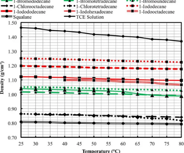
Figure 3.5. Measured fluid densities as a function of temperature for the candidate forming fluids and the TCE solution benchmark. . ...63
Figure 3.6. Measured fluid viscosities as a function of temperature for the candidate forming fluids and the TCE benchmark. ...65
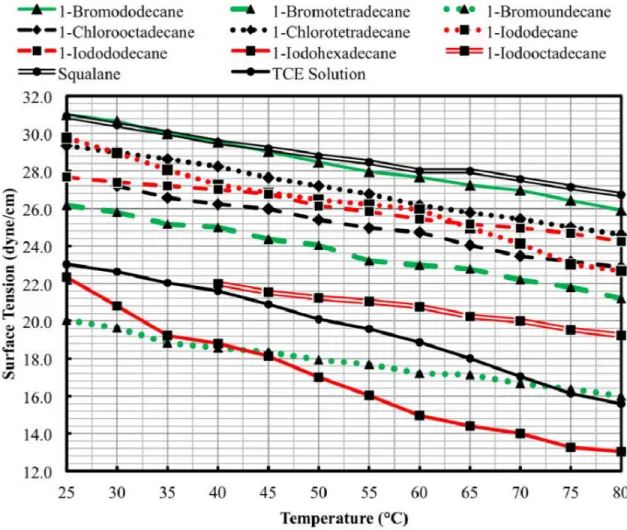
Figure 3.7. Measured surface tensions as a function of temperature for the candidate forming fluids and the TCE benchmark. ...66
Figure 3.8. Predicted settling velocities as a function of temperature for the candidate forming fluids and the TCE solution benchmark. ...69
Figure 3.9. Estimated specific heat capacities as a function of temperature for the candidate forming fluids and the TCE benchmark. ...72
Figure 3.10. Estimated thermal conductivities as a function of temperature for candidate forming fluids and the TCE benchmark. ...73
ix
Figure 3.11. Calculated Weber numbers as a function of temperature for candidate forming fluids and the TCE solution benchmark. ...75 Figure 4.1. Custom-made, 45 cm tall, glass jacketed formation column equipped with a
100 ml removable flask, and a 1 mm marking used to measure the terminal
velocity of forming kernels. ...88 Figure 4.2. Orifice size vs. nozzle jet velocity for proper stream breakup. ...89 Figure 4.3. Precursor solution titration curve showing initial gelation (square), complete
gelation (triangle), and pH color indication provided by malachite green. ...94 Figure 4.4. Optical images of air dried (a) and fully sintered (b) YSZ kernels produced in
silicone oil, used as a control benchmarks for kernel production in this
study. ...98 Figure 4.5. Thermogravimetric analysis of the alternative forming fluids. ...99 Figure 4.6. Kernels produced in each of the alternative forming fluids. ...101 Figure 4.7. SEM image showing a surface void and cracks in a sintered YSZ kernel
formed in iodododecane and bubble formed on a kernel during gelation in
iodododecane (inset). ...103 Figure 4.8. SEM image of a YSZ kernel formed in silicone oil. ...107 Figure 4.9. SEM image of a YSZ kernel formed in bromotetradecane. ...107 Figure 4.10. SEM image of the interior and exterior of a YSZ kernel formed in
bromotetradecane. ...108 Figure 4.11. XRD data for YSZ kernels formed in each of the forming fluids considered in
this study. ...109 Figure 4.12. SEM image of a polished cross-section of a YSZ kernel formed in
bromotetradecane. ...112 Figure 4.13. SEM image of the surface of a YSZ kernel formed in bromotetradecane. ...112 Figure 4.14. FTIR analysis of pure bromotetradecane and at the simulated end-of-life. ...114 Figure 5.1. SEM image showing a surface void and cracks in a sintered YSZ kernel
formed in iodododecane and bubble formed on a kernel during gelation in
x
Figure 5.2. Custom-made, 45 cm tall, glass jacketed formation column equipped with a 100 ml removable flask, and a 1 mm marking used to measure the terminal
velocity of forming kernels. ...127 Figure 5.3. COMSOL geometry for the terminal velocity model. ...131 Figure 5.4. COMSOL geometry for the heat transfer model ...136 Figure 5.5. Predicted gelation time for a 1,342 µm YSZ kernel in bromotetradecane as a
function of the thermal conductivity and specific heat capacity of the
forming fluid. ...139 Figure 5.6. Predicted gelation time for a 1,342 µm YSZ kernel in chlorooctadecane as a
function of the thermal conductivity and specific heat capacity of the
forming fluid. ...140 Figure 5.7. Predicted gelation time for a 1,342 µm YSZ kernel in bromotetradecane as a
function of the thermal conductivity and specific heat capacity of the
precursor solution. ...140 Figure 5.8. Gelation times of bromotetradecane and chlorooctadecane versus thermal
diffusivity changes in the precursor solution. ...143 Figure C.1. Stitched stereoscopic image of kernels on 1-inch diameter holder. ...168 Figure C.2. Kernel edges located in ImageJ of stitched kernel image. ...169
xi
LIST OF TABLES
Table 2.1. Previous internal sol-gel techniques. ...27
Table 3.1. Previous internal sol-gel techniques. ...57
Table 3.2. Primary selection criteria for an alternative forming fluid. ...59
Table 3.3. Potential replacement forming fluids selected for property testing. ...61
Table 3.4. Secondary selection criteria of forming fluids and the TCE solution benchmark. ...61
Table 3.5. Predicted critical properties of the potential forming fluids and TCE. ...71
Table 3.6. Settling velocities (vt), heat transfer times (th), and minimum column heights (Hmin) predictions at 60 °C for the potential forming fluids and the TCE solution benchmark. ...73
Table 4.1. Operational setpoints for YSZ kernel formation in the present study. ...91
Table 4.2. Size and shape measurements of YSZ kernels formed in the present study. ...106
Table 4.3. YSZ kernel densities measured by gas pycnometry. ...110
Table 4.4. Pore and grain sizes measured in YSZ kernels formed in the present study. ...111
Table 5.1. COMSOL terminal velocity model parameters. ...130
Table 5.2. Measured densities, and estimated specific heat capacities and thermal conductivities of bromotetradecane and chlorooctadecane, and assumed precursor solution values. ...134
Table 5.3. Estimated and measured terminal velocity calculations for a 1,342 µm drop diameter YSZ kernel falling through bromotetradecane and chlorooctadecane ...138
Table 5.4. Standard heats of formation for the species involved in YSZ gelation ...145
Table B.1. ICP-MS metal solution results. ...167
Table D.1. Silicone oil EDS quantitative data. ...171
Table D.2. Bromotetradecane EDS quantitative data. ...171
Table D.3. Chlorooctadecane EDS quantitative data. ...172
xii
LIST OF ACRONYMS
2EH 2-ethyl-1-hexanol AGR Advanced Gas Reactor ATR Advanced Test Reactor
AVR Arbeitsgemeinschaft Versuchsreaktor cercer ceramic-ceramic (matrix)
cermet ceramic-metal (matrix) CFR Code of Federal Regulations CSM Colorado School of Mines
DI Deionized water
EDS Energy-Dispersive x-ray Spectroscopy FTIR Fourier Transform Infrared Spectrometry HAP Hazardous Air Pollutant
HMTA hexamethylenetetramine HTR High Temperature Reactor HTTR High-Temperature Test Reactor HU Hexamethylenetetramine-urea solution
ICP-MS Inductively Coupled Plasma Mass Spectroscopy INL Idaho National Laboratory
IPyC Inner pyrolytic carbon layer
KEMA Keuring van Electrotenische Materialen Arnhem KFA Kernforschungsanlage
LWR Light Water Reactor MSDS Material Data Safety Sheet NGNP Next Generation Nuclear Plant NuMat Nuclear Materials Conference OPyC Outer pyrolytic carbon layer ORNL Oak Ridge National Laboratory PTFE polytetrafluoroethylene
xiii SEM Scanning Electron Microscopy SiC silicon carbide
SNAM Nucleare S.p.A. Milan TCE trichloroethylene
TGA Thermogravimetric analysis
THTR Thorium High-Temperature Reactor TRISO TRi-structural ISOtropic
UH Urea-hexamethylenetetramine solution UCO uranium oxycarbide
VHTR Very High Temperature Reactor VOC Volatile Organic Compound YSZ Yttria-stabilized zirconia
xiv DEDICATION
This thesis is dedicated to my parents for their love and support throughout my academic career and beyond.
1 CHAPTER 1 INTRODUCTION
The Very High Temperature Reactor (VHTR) is a gas-cooled nuclear reactor capable of utilizing its excess heat for high-temperature chemical processing (Abram and Ion, 2008). TRi-structural ISOtropic (TRISO) fuel kernels provide the fissionable material, and helium gas removes and transfers fission heat away from the graphite moderated reactor core. The current TRISO kernel material selected by the United States is a combination of uranium oxide and uranium carbide fuel, which provides a higher thermal conductivity compared to oxide fuel alone, which helps prevent fuel cracking caused by thermal expansion.
The current TRISO kernel production process uses trichloroethylene (TCE) as the forming fluid in an internal gelation sol-gel production column. Over time, gelation byproducts in the forming fluid inhibit complete gelation, and the forming fluid is periodically replaced. Because the spent forming fluid contains both hazardous and radioactive components, it is considered a mixed waste, which is difficult and expensive to treat or dispose of. At current laboratory scales this is not a significant issue, but it will become a larger problem when the process is scaled to industrial production. Currently, approximately 1.5 gallons of TCE are used to produce 1 kg of uranium oxycarbide kernels (Niedzialek, 2011). Assuming a disposal cost for low-level mixed waste of $75/gallon, this equates to a disposal cost of approximately $112,500 per ton of uranium oxycarbide (UCO) kernels produced. Changing the forming fluid to produce a non-hazardous waste product will significantly reduce mixed waste production during fuel fabrication and improve process economics.
2
The goal of this thesis is to find an alternative formation fluid for TRISO fuel kernel production that does not result in a mixed hazardous waste stream the forming fluid.
To achieve the research goal, the following objectives were met:
• Screen existing chemical databases for replacement forming fluids,
• perform property testing on the most promising candidates,
• make a recommendation for three candidates for process testing, and
• characterize surrogate kernels and forming fluids to yield a final recommendation for production-level testing.
A screening process selected ten potential replacement forming fluids from a list of ~10,800 chemicals, and experimental testing determined the fluids’ density, viscosity, and surface tension from 25 °C to 80 °C. An evaluation of these properties narrowed the alternatives to three fluids recommended for kernel production testing as replacements for TCE: 1-bromotetradecane, 1-chlorooctadecane, and 1-iodododecane. Bench-scale production of yttria-stabilized zirconia kernels in these three alternative fluids investigated the forming abilities of each fluid, and the characterization results lead to the recommendation of 1-bromotetradecane for further testing at production level.
Initial estimates of the forming kernels’ terminal velocities and heat transfer times yielded a potential formation column height of 45 cm. A custom-built glass jacketed forming column was used to produce kernels in the three chosen alternative fluids, with gelation completing only in bromotetradecane. Kernel production in chlorooctadecane did not complete in the forming column length. Kernel production in iodododecane resulted in poor geometries from the formation of byproduct bubble, leaving an indent on the kernel surfaces. This lead to a
3
new research goal of determining where the initial terminal velocity or heat transfer time estimates were inaccurate and to determine a more accurate gelation time estimate.
Investigation into terminal velocity and heat transfer models determined that the precursor solution’s assumed thermal properties inaccurately predicted the gelation times. Using measured terminal velocities in a COMOSL heat transfer model, an effective thermal diffusivity for the precursor solution was estimated that matches the gelation times exhibited in bromotetradecane and chlorooctadecane.
Chapter 2 presents the background information relevant to the research. The background information includes a discussion of the VHTR, its TRISO fuel type, and past kernel fabrication techniques used for TRISO kernel production: the water extraction process, the external gelation process, and the internal gelation process. Advantages and disadvantages of each process are presented, leading to the selection of the internal sol-gel process, which is the most advantageous for surrogate zirconia production. Zirconia, urania, and uranium oxycarbide production chemistries, the three most common sol-gel TRISO kernel pathways, are also presented. The chapter concludes with issues related to the creation of the mixed hazardous waste stream.
Chapter 3 presents the selection and identification of the ten most promising candidate forming fluids with subsequent property testing. The chapter presents density, viscosity, and surface tension measurements for each fluid from 25 °C to 80 °C. The property values inform the calculation of the settling velocity, heat transfer time, and sphere formation potential of each fluid over the measured temperatures, leading to the recommendation of the three most promising forming fluid candidates for laboratory scale kernel production; 1-bromotetradecane, 1-chlorooctadecane, and 1-iodododecane.
4
Chapter 4 presents the zirconia kernel production tests and the subsequent characterization of the produced kernels and forming fluids. Characterization of kernel size, shape, density, crystalline structure, and atomic composition are presented, and the used formation fluids are characterized by Fourier-Transform Infrared spectroscopy (FTIR) analysis and neutron activation analysis (NAA). The chapter concludes with a final recommendation of bromotetradecane for future study at the process level.
Chapter 5 presents an in depth analysis of the heat transfer properties of the precursor solution and forming fluids by means of analytical and computer modeling. A COMSOL model, developed to estimate the terminal velocity of the precursor solution in the alterative fluids during free-fall is presented. The analytical method for gelation time, described in Chapter 3, is updated to include new kernel sizes and measured terminal velocities. This leads to a sensitivity analysis of the impact of the thermal properties of the precursor solution and forming fluid on gelation time. This chapter also presents a COMSOL heat transfer model used to determine a more appropriate estimate for the thermal diffusivity of the precursor solution by changing its thermal conductivity and specific heat capacity to match the gelation times observed in bromotetradecane and chlorooctadecane.
Chapter 6 presents the summary and final conclusions of the study, and Chapter 7 provides recommendations for future work based on this research.
Appendix A presents the end-of-life bromotetradecane neutron activation analysis, Appendix B presents the precursor solution ICP-MS metal level results, Appendix C describes the kernel, pore, and grain size image analysis techniques, and Appendix D presents the quantitative energy dispersive spectroscopy (EDS) data. Digital annexes are available online for the terminal velocity and heat transfer COMSOL models.
5 1.1. References
Abram, T., and Ion, S., “Generation-IV nuclear power: A review of the state of the science,” Energy Policy, 26, (2008), 4323-4330.
6 CHAPTER 2 BACKGROUND
This chapter presents background information pertinent to the research project in a top-down approach. The first section presents information on the Very High Temperature Reactor (VHTR) and its various designs and fuel types. The TRi-structural ISOtropic (TRISO) fuel used in the VHTR is presented in the following section, and then subsequent sections cover the various production methods and fuel types. Sol-gel chemistry information is presented for the internal gelation process currently used by the United States for TRISO kernel production, including the production of zirconia, urania, and uranium oxycarbide.
2.1. Very High Temperature Reactor
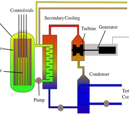
The VHTR (Figure 2.1) is a helium gas-cooled thermal reactor capable of outlet temperatures of up to 1000 °C (Abram and Ion, 2008). It is the second iteration of the High Temperature Reactors (HTRs) first proposed at Harwell in the 1950s (Huddle, 1959). The operating temperature is much higher than a typical light water reactor, and permits the VHTR to be a versatile tool for commercial applications. The reactor can be configured in either a prismatic or pebble bed design (Abram and Ion, 2008). The prismatic core is characterized by hexagonal assembly blocks of graphite used as the reactor’s moderator and reflector (see Figure 2.2c). Fuel compacts (see Figure 2.2b) and cooling channels (see Figure 2.2c), are located within these blocks and are positioned in an annular or cylindrical arrangement. Each fuel compact consists of a mixture of graphite binder and TRi-structural ISOtropic fuel particles (TRISO, Figure 2.2a) (Abram and Ion, 2008; Idaho National Laboratory et al., 2005).
7
Figure 2.1. Very High Temperature Reactor prismatic core design with process heat utilization.
a) particles b) compacts c) assemblies Figure 2.2. Idaho National Laboratory's TRISO fuel particles, compacts, and assemblies (Idaho National Laboratory et al., 2005).
8
The pebble bed design contains ~6 cm graphite moderated spheres containing the TRISO fuel particles, and is capable of continuous refueling. The large spheres move through the core in a “gumball machine” type movement. Both the prismatic and pebble bed design are passively safe, and the prismatic design is capable of ~5,000 operational hours before refueling, or approximately three times longer than current light water reactors (Abram and Ion, 2008).
The VHTR is primarily designed to use a once-through uranium cycle, but also has the capability to use thorium-based (Fuller, 1988) or transmutation fuels (Versluis et al., 2008). The reactor system will be licensed for a 60-year operating period (Wright, 2006). The VHTR can couple with other processes that utilize its high outlet temperatures, such as chemical production of hydrogen (see Figure 2.1).
The Next Generation Nuclear Plant (NGNP), currently in design by the United States, will be the latest iteration of the VHTR concept (Idaho National Laboratory et al., 2005). Previously, two other VHTRs operated in the US: Peach Bottom in Pennsylvania (Burnette and Baldwin, 1980), and the Fort St. Vrain reactor in Colorado (Wright, 2006). The Peach Bottom reactor operated for part of 1967, and Fort St. Vrain reactor operated from 1979-1989 (Wright, 2006). Other VHTRs from around the world include Dragon in the U.K. (1964-1975) (Simon and Capp, 2002), the Arbeitsgemeinschaft Versuchsreaktor (AVR) in Germany (1966) (Wright, 2006), the Thorium High-Temperature Reactor (THTR) in Germany (Baumer and Kalwowski, 1991), and the High-Temperature Test Reactor (HTTR) in Japan (1985) (Wright, 2006) which has been online since 1997 and is the only HTR still in operation today. The AVR was the first pebble bed reactor, and provided valuable firsthand knowledge for operation of the THTR (Wright, 2006).
9
The Fort St. Vrain reactor contained 1,482 hexagonal fuel elements, each consisting of a graphite block loaded with TRISO particles of uranium or thorium kernels (Fuller, 1988). The reactor reached a maximum fuel temperature of 1,260 °C (Huschka and Vygen, 1977). Four circulators pressurized the helium coolant to 700 psia (Fuller, 1988). After the coolant left the core, its heat flashed water in twelve steam generators, similar to many other nuclear or fossil fueled plants (Fuller, 1988). The generators created steam with a pressure of 2,400 psig and temperature of 1,000 °F, which spun the turbine generators (Fuller, 1988). The Fort St. Vrain VHTR had an overall efficiency ~39% (Fuller, 1988) with an electrical output of 330 MWe (Huschka and Vygen, 1977). The following section presents information on the TRISO fuel type used in the reactors described above.
2.2. TRISO Fuel
TRISO fuel particles are comprised of a spherical fissile kernel surrounded by layers of pyrolytic graphite and silicon carbide. TRISO particle fuel kernels typically consist of uranium oxide, uranium carbide, or uranium oxycarbide (UCO). Carbon and silicon carbide (SiC) layers coat the 200-500 µm diameter kernels (Figure 2.3). A carbon buffer absorbs the kinetic energy of ballistic fission fragments, accumulates gaseous fission products, and accommodates kernel swelling (Petti et al., 2002). The silicon carbide layer acts as a pressure and diffusion barrier, and the two pyrolytic graphite layers protect the silicon carbide layer during production and irradiation (Figure 2.3). Although layer thicknesses vary between manufacturers, fuels developed in the United States typically have a buffer layer that is ~100 µm thick, a silicon carbide layer ~35 µm thick, and pyrolytic carbon layers ~40 µm thick (Petti et al., 2002).
10
In the United States, TRISO kernels are currently produced by an internal sol-gel chemistry process first developed in the Netherlands (Kanij, Noothout, and Votooek, 1973). A chilled precursor broth drops into a hot column of organic liquid via a vibrating needle. The temperature difference decomposes hexamethylenetetramine (HMTA) in the broth, producing ammonia, which drives the hardening of the precursor as it falls through the forming fluid. This creates a sphere as the precursor droplet reaches a steady state velocity, allowing interfacial surface tension to control the kernel’s geometry.
2.3. Previous Kernel Fabrication Techniques
Ceramic sol-gel sphere fabrication has been under development for over 70 years, with the original concept developed by the catalyst industry in the 1940s (Heard, 1944). Active development of sol-gel based nuclear fuels in the United States continued until 1972 when the fast reactor programs concentrated a larger effort on fast reactor fuels in pellet form (Beatty, Norman, and Notz, 1979). This did not stop other countries from pursuing development of the
Outer pyrolytic carbon layer (OPyC, 30-60 µm) !
SiC layer (30-50 µm) !
Inner pyrolytic carbon layer (IPyC, 30-60 µm) !
Graphite buffer layer (80-150 µm) !
Fuel kernel (300-800 µm diameter) UCO – UO2, UC, UC2
!
11
sol-gel fabrication technique, which can include additional materials in the spheres, such as silicon carbide (Hunt et al., 2010). U.S. interest in sol-gel processing resumed in 1977 based on concerns over remote nonproliferation fabrication techniques and the need for improved cladding behavior to allow more severe thermal ramping during normal reactor operation (Beatty, Norman, and Notz, 1979).
The sol-gel fabrication process uses fewer process steps than typical pellet fabrication methods (Beatty, Norman, and Notz, 1979). The liquid based operation produces microspheres in a dust-free environment, and avoids the powder pretreatment, pre-slugging, and pelletization steps commonly used in the pellet fuel fabrication (Beatty, Norman, and Notz, 1979). This greatly reduces radioactive exposure during fabrication and maintenance (Beatty, Norman, and Notz, 1979). Heavy metal nitrate solutions, such as uranyl nitrate, are the usual product of reprocessing. Directly using this material avoids the conversion step in the closed fuel cycle, if reprocessed materials are reused in the sol-gel process.
Other advantages of the sol-gel process include (Beatty, Norman, and Notz, 1979; Ganguly, 1993; Robisson et al., 2007):
• Improved handling procedures possible with liquids compared to the powder-pellet method,
• versatility of using uranium, thorium, plutonium and mixtures of each,
• simpler mechanical operations, which make remote operation easier,
• lower sintering temperatures owing to a smaller crystalline structure, and
12
Three different sol-gel techniques can produce spherical ceramics (Beatty, Norman, and Notz, 1979):
• Water extraction gelation – developed at the Oak Ridge National Laboratory (ORNL) (Haas, Clinton, and Kleinsteuber, 1966),
• external gelation – developed at Nucleare S.p.A. Milan (SNAM) Progetti in Italy (Beatty, Norman, and Notz, 1979), and
• internal gelation – developed at Keuring van Electrotenische Materialen Arnhem (KEMA) in the Netherlands (Kanij, Noothout, and Votooek, 1973).
The basics of each technique are similar in nature, with a broth containing the nuclear fuel (or ceramic precursor for non-nuclear materials) hardened by gelation in a column, during which the precursor broth forms spheres by interfacial surface tension. The major differences lie in the broth formation and gelation steps. All of the processes start with an acid deficient (usually nitrated) broth. The partial neutralization, or acid deficiency (NO3-/U ratio), keeps the broth close to the thermodynamic tipping point for the completion of the gelation (Collins et al., 2004). Formation of spheres during settling drives the falling broth from its temporary equilibrium to the final gelled state, and gelation occurs over seconds instead of the hours required when the broth naturally gels at the broth conditions. The spheres are then washed, dried, calcined, and sintered. Calcination temperature and time vary based on the constituents in the green spheres and the kernel’s desired crystalline structure and pore size. The three sol-gel production processes are detailed in the following subsections.
13 2.3.1. Water Extraction Process
In the water extraction process, an organic alcohol dehydrates the precursor broth until gelation occurs. As water is extracted from the broth, the colloidal particles become concentrated until the point of gelation, which initiates rapid gelation by precipitation of ammonium diuranate (Beatty, Norman, and Notz, 1979). Water extraction takes place by mass transfer across the phase boundaries of the broth and the organic alcohol, and the gelation rate is dictated by the rate of the mass transfer. Because of this limitation, this method can only be used for highly acid-deficient solutions (Zimmer, Naefe, and Ringel, 1978).
The forming fluid for the water extraction process developed at ORNL (Figure 2.4) currently consists of 2-ethyl-1-hexanol (2EH) at temperatures between 25-35 °C and previously consisted of 2-methylpentanol or a CCl4-isopropyl alcohol mixture (Haas and Clinton, 1966). A two-fluid nozzle delivers the broth to the formation column with the broth encapsulated by the forming fluid as it enters the formation column.
As the acid-deficient droplet enters the forming fluid column, the forming fluid extracts water from the broth and partially densifies the forming kernel. Interfacial surface tension allows the falling broth to form spheres by surface energy minimization. Typical broth formulations consist of an ammonia solution (3.0 M NH4OH-0.5 M N2H4), mixed with a 0.5-2.3 M NO3- solution (stabilized with formic acid) (Haas, Clinton, and Kleinsteuber, 1966). The ammonia-hydrazine solution is added slowly until the pH of the two mixtures reaches 7.0.
14
For proper gelation, the spheres must remain suspended in the organic alcohol long enough to be relatively dry for handling purposes (Haas and Clinton, 1966; Beatty, Norman, and Notz, 1979). Broth molarity and droplet size dictate the gelation time, which can range from 2 to 20 minutes (Haas and Clinton, 1966). Surfactants added to the formation fluid prevent the spheres from sticking to one another, or to the formation column (Haas, Clinton, and Kleinsteuber, 1966). Ethomeen S/15 and Paraplex G-62 were the original surfactants, but Span™-80 results in improved sphere formation with smooth, nonsticking surfaces (Beatty, Norman, and Notz, 1979). Formation columns can also be fluidized for low molar-long gelation time broths. As the kernels reach complete water extraction, they densify and can no longer be fluidized, gathering at the bottom of the column (Haas and Clinton, 1966).
Broth creation Drop formation Suspension in solvent Water extraction Aging/washing Drying
Calcination and sintering
15
The water extraction process developed at ORNL during the 1960s produced spheres of ThO2, PuO2, UO2, (Th,U)O2, (U,Pu)O2, (Th,Pu)O2, and (U, Zr)O2 containing rare earth, and other actinides for use in gel-sphere-pac fuel (Haas, Clinton, and Kleinsteuber, 1966; Beatty, Norman, and Notz, 1979; Haas and Clinton, 1966). The issues discussed in the following subsection led to the abandonment of this technique.
2.3.1.1. Problems With Water Extraction
When water saturates the forming fluid, partially gelled spheres have a tendency to stick to one another and the side of the column, causing clusters that may clog the forming apparatus (Beatty, Norman, and Notz, 1979). These large clusters may not completely gel. Partially gelled spheres may be aged in 2EH to remove the remaining water if the surface is gelled enough to not agglomerate with other spheres (Beatty, Norman, and Notz, 1979). The water extraction process has longer average gelation times than other methods.
If the mass transfer of the water to the forming fluid is too rapid, the spheres will quickly gel on the surface, and water extraction from the interior will distort or crack the spheres during the ageing process (Beatty, Norman, and Notz, 1979). To address this issue, the water extracting organic forming fluid must have a low to medium solubility with water. Forming fluids with high water solubility tend to have smaller interfacial surface tensions which form hardened spheroids with an increased tendency to crack (Beatty, Norman, and Notz, 1979). Flowing the 2EH at a rate 100-150 times that of the broth lowers the overall water content of 2EH (Beatty, Norman, and Notz, 1979). This creates a steady state water content in the range of 1-1.5 vol% (Beatty, Norman, and Notz, 1979). However, this solution only works with a two-fluid nozzle, and a large amount of warm forming fluid must be available in a reservoir to accommodate this method.
16
If a two-fluid nozzle is not used, the solids tend to accumulate at the solvent-broth interface and degrade the surface conditions of the sphere. Surface accumulations are cleaned with nitric acid which results in a uranium loss of about 2-4%, and a solvent loss of 0.5% (Beatty, Norman, and Notz, 1979). Regardless of the cleaning technique, 2,000-5,000 ppm carbon inclusions are present in sintered UO2 kernels, owing to the decomposition of retained 2EH or surfactants (Haas, Clinton, and Kleinsteuber, 1966). Researchers have investigated many variations on drying, calcination, and sintering, but no solution to the additional carbon content has been found (Haas, Clinton, and Kleinsteuber, 1966).
As the kernels densify in the column, the settling velocity increases, which may lead to shape formation issues. Shape and pore formation are limiting factors for the water extraction process, with larger kernels exhibiting cracking failures during calcination. Based on the documented issues, the water extraction method is not useful for developing microspheres of urania larger than 600 µm (Beatty, Norman, and Notz, 1979). As a consequence, the external and internal techniques are described in Sections 2.3.2 and 2.3.3, respectively, will result in superior kernel fabrication in the present research’s investigated size range.
2.3.2. External Gelation Process
The external gelation process uses gaseous or aqueous forms of ammonia to cause gelation externally to the broth, and is also known as the gel-support precipitation technique (Charollais et al., 2004). First invented in 1962 in Italy, the SNAM process included this fabrication method in 1970. Kernforschungsanlage (KFA)-Juelich in Germany, Bhabha Atomic Research Centre in India, Harwell in the United Kingdom, General Atomics in the United States, and KEMA in the Netherlands, also developed external gelation methods (Ganguly, 1993; Beatty, Norman, and Notz, 1979).
17
In the external gelation process, a water soluble organic polymer (typically polyvinyl alcohol), contained in a heavy metal broth, supports the spherical shape formation. The broth then contacts an ammonia-containing fluid which diffuses into the sphere and precipitates the heavy metal in the broth. Spherical drops form during free fall as a result of the broth’s surface tension. More than one delivery system can result in sphere formation, such as: dripping from a capillary tube, two-fluid vibrating needle injection, or natural breakup of a laminar stream. External gelation processes typically utilize a quick gas exposure followed by liquid contact which also supplies the ammonia used for gelation (Ganguly, 1993; Beatty, Norman, and Notz, 1979). Figure 2.5 presents a basic flow diagram of the external gelation process.
The broth consists of the desired heavy metal nitrate, mixed with a water soluble organic polymer (for viscosity and density adjustment), additives, and modifiers (for pH adjustment and
Broth creation Drop formation Surface gelation Aging/washing Dehydration Drying
Calcination and sintering
18
polymer acid-attack prevention) (Beatty, Norman, and Notz, 1979). Previous organic polymers include hydroxpropyl methyl cellulose (Methocel), polyvinyl alcohol, dextran, natural gums, and Wisprofloc (Beatty, Norman, and Notz, 1979; Charollais, et al., 2004). The additive and modifiers include tetrahydrofurfuryl alcohol, formamide, urea, ammonium nitrate, dioxane, acetamide, and glycine (Beatty, Norman, and Notz, 1979). These prevent ammonia conversion of the uranyl ions into ammonium diuranate, which gives an uneven shrink distribution in the forming kernels (Zimmer, Naefe, and Ringel, 1978). These additives may require additional considerations during the washing and calcination stages.
Exposure of an acid deficient solution to ammonia gas at ~100 °C forms a surface skin layer in less than 0.02 seconds (Haas et al., 1980). The quick gelation is both an advantage and disadvantage of this formation method. The broth’s response to an external gelation source is the fastest of the production methods, but the kernel experiences shape problems if the gelation is carried out too swiftly. External gelation broths typically contain additions to increase viscosity which aids in faster sphere formation (Zimmer, Naefe, and Ringel, 1978). After formation, ammonia nitrate (or other salts) must be removed prior to drying to prevent cracking (Beatty, Norman, and Notz, 1979). This process typically uses dilute ammonia solutions which also keep the heavy metals from going back into solution (Beatty, Norman, and Notz, 1979). Distilled water removes residual ammonia from the sphere’s exteriors. Kernels produced by the external gelation method typically go through an additional dehydration step to remove residual water and organic compounds before calcination. Sintering processes take place in an Ar-4% H2 atmosphere to reduce the UO3 created in the gelation process to UO2. Temperature and times vary depending on the size of the kernels and the desired density. Nuclear materials that have been produced by external gelation include UO2, ThO2, (U, Th)O2, (U, Pu)O2, and (U, Ce)O2
19
(Zimmer, Naiefe, and Ringel, 1978; Ganguly, 1993; Ringel and Zimmer, 1979; Zimmer et al., 1988). The external gelation process is still used for TRISO fuel kernel production; however, the internal gelation process is used in the United States for kernel production based on formation issues related to the external gelation process. These process issues are presented in the following subsection.
2.3.2.1. Problems With External Gelation
Due to quick gelation times in ammonia-based gases, external gelation broths must first enter a gas that does not contain ammonia for proper formation before initial gelation begins (Haas, 1992). However, sphere deformation may occur at the gas-liquid interface if drop formation occurs in a gas that is not an ammonia donor (Haas, 1992). A two-gas system, where formation occurs in air prior to exposure to an ammonia-based gas strengthens the surface of the sphere, reducing deformation (Beatty, Norman, and Notz, 1979). Bubbling ammonia gas through the ammonia-containing liquid creates a bubble blanket at the liquid-gas interface, which also lessens the chance of a splatter. The British use this technique to address deformation issues (Beatty, Norman, and Notz, 1979). The ammonia gas is supplied to the column at ~100 °C, which is a problematic containment issue due to its chemical nature and properties at this temperature, especially when used in a two-gas system (Zimmer, Naefe, and Ringel, 1978).
Externally gelled spheres have a tendency to reabsorb water after the drying process. This rehydration can occur so quickly that the spheres burst before being introduced to a furnace (Beatty, Norman, and Notz, 1979). KFA avoided this problem with a continuous belt dryer, which did not allow the spheres to cool and reabsorb water (Beatty, Norman, and Notz, 1979).
20
Uranium spheres produced via external gelation with low molar broth concentrations result in a large shrinkage factor which forms nonspherical kernels and leads to an increase in cracking failures (Fu et al., 2004). This issue is common with the sol-gel processing of uranium, and a high molar concentration broth alleviates the problem. The KEMA process has difficulty in producing spheres larger than 100 µm in diameter with the external gelation process. (Beatty, Norman, and Notz, 1979).
The external gelation process potentially utilizes ammonia in both a gaseous and liquid forms, which will produce a large amount of ammonia-based waste. The external gelation process also requires a more elaborate equipment setup than the internal gelation systems described in the next section.
2.3.3. Internal Gelation Process
The internal gelation process uses water soluble chemicals located within the broth as the ammonia donors via thermal decomposition. The process requires an acid deficient heavy metal precursor mixed with urea and hexamethylenetetramine (HMTA). The mixed broth is chilled to ~0 °C to prevent premature gelation.
The first step in creating a broth is the partial neutralization to the point where gelation has almost started, but is not complete without the heat required to decompose the HMTA and begin the final gelation (Zimmer, Naefe, and Ringel, 1978). Stable broths should stay in solution for about an hour without gelation at low temperatures (0-10 °C). Thermal decomposition of HMTA generates ammonia which causes kernel gelation. The urea complexes with the uranium, stabilizes the broth, prevents premature gelation, and also decomposes at elevated temperatures to produce additional ammonia (Barnes et al., 2008). Because the ammonia donating chemical is
21
uniformly distributed within the broth, the rate of gelation is fairly constant throughout the gelling sphere, as long as the heat transfer is rapid and the drop size is sufficiently small (Beatty, Norman, and Notz, 1979). The internal gelation process is the most common method of kernel production, and is covered in detail in this section. KEMA in the Netherlands originally developed the process, which is colloquially given the same name. Figure 2.6 presents a simplified flow sheet of the internal gelation process.
Internal gelation offers several advantages for spheroid production (Hunt, Montgomery, and Collins, 2010; Arima et al., 2005; Alder, Ledergerber, and Stratton, 1987; Collins, 2005; Zimmer, Naefe, and Ringel, 1978):
• Better control of gelation time,
• improved control of microsphere size,
• enhanced reproducibility,
Broth creation
Drop formation
Gelation in forming fluid
Aging/washing
Drying
Calcination and sintering
22
• good homogenous incorporation of fine particles of non-radioactive materials,
• low sintering temperature,
• simplified flow sheets for carbide based fuels which reduces the production of pyrophoric dust,
• precipitation of metal ions and geometric shape formation can take place simultaneously,
• control of crystal morphology in the gelled spheres, and
• large-scale engineering processing.
Like all multi-step chemical processes, internal gelation is controlled by the slowest step. For urania spheres, the gelation rate is controlled by the slowest of three processes (Haas et al., 1980):
• The heat transfer required to bring the kernel temperature to the forming fluid’s temperature,
• the decomposition of HMTA to release ammonia for gelation, or
• the precipitation of hydrated UO3 by the ammonia.
The HMTA decomposition (Equation 2.1), urea decomposition (Equation 2.2), and metal hydrolysis (Equation 2.3) reactions can be written as (Haas et al., 1980; Idemitsu et al., 2003; Robisson et al., 2007):
!!! !!!+ 10!!! ↔ 4!!!!" + 6!"!# (2.1)! !" !" !+ 3!!! ↔ !!!+ 2!!!!" (2.2)!
!!!+ !!
23
As HMTA ([CH2]6N4) decomposes into ammonia and formaldehyde (Equation 2.1), the broth’s pH rises, which precipitates the metal after it hydrolyses (Equation 2.3). ORNL concluded that the controlling steps for urania internal gelation are dependent on the formation temperature (Haas et al., 1980). Below 40 °C the HMTA decomposition is controlling, and above 40 °C the heat transfer from the forming fluid to the droplet controls the process, with film resistance controlling heat transfer (Haas et al, 1980).
Heat transfer from the forming fluid to the forming spheres is fairly rapid, and the resulting gelation times have a small dependence on the kernel size (Haas et al., 1980). This was a major driving force for ORNL to work with the internal gelation process for preparation of spherical kernels with diameters greater than 1,200 µm (Haas et al., 1980). ORNL demonstrated that increasing the metal concentration while keeping a stable broth increases the time a broth can last at low temperatures and shortens gelation time at higher temperatures (Haas et al., 1980).
The generation of NH4OH by the decomposition of HMTA will proceed quickly based on the HMTA’s homogenous distribution in the broth, and because mass transfer is not required (Haas et al., 1980). The HMTA buffers the broth during gelation, and the pH of the broth must be less than 7.0 for any metal ion to precipitate properly (Collins, 2005).
The broth needs to be delivered through the nozzle/needle in the laminar regime to prevent the broth from breaking apart into smaller droplets (Haas, 1992). According to Oak Ridge experiments, the jet diameter should be about half of the intended drop diameter (specifically ~2.2 times smaller) (Haas, 1992). The ORNL experiments demonstrated similar breakup results as those calculated by the Rayleigh model, which predicts that the jet diameter
24
should be 1.89 times larger than the droplet size (Lefebvre, 1989). Figure 2.7 presents a conceptual drawing of the laminar flow stream breakup and kernel development.
Smaller drops may collect and coalesce at the air-forming fluid interface. Introducing an upward flow in the forming fluid reduces this coalescence while allowing droplet entrapment (Ganatra et al., 2008). The countercurrent flow not only improves the forming fluid residence time, it also helps to maintain the temperature of the forming column (Ganatra et al., 2008). The presence of Span™-80 or other surfactants prevent coalescence of liquid drops by modifying surface tension at the liquid-liquid interface (Segal, 1989). For droplets smaller than 1,500 µm in diameter, the needle should be ~2 cm over the liquid surface and directed at an angle between
Precursor solution Vibrating needle
Forming fluid
Forming vessel
Developed kernel
25
30-45 °C (Haas, 1992). This reduces droplets collecting at the liquid-air interface and decreases the force of the droplets entering the viscous medium.
The washing/aging of green kernels physically removes the forming fluid, leaches NH4NO3 and other soluble constituents from the broth, and allows for complete gelation before calcination (Haas et al., 1980). For viscous forming fluids such as silicone oil, a preliminary wash with a more volatile organic solvent may be needed before the aging step in an ammonia-based solution (Haas et al., 1980). Previous cleaning methods have used carbon tetrachloride (Pathak et al., 2008; Haas et al., 1983) and kerosene (Idemitsu et al., 2003; Arima et al., 2005) for this step. The washing needs to remove materials that may be considered contaminants in the final product, are difficult to calcine from the kernel, or that will crack the sphere during the heat treatment steps.
During formation, water is extracted from the surface of the forming kernel and a small amount may go into solution with the forming fluid or vaporize with a low-boiling azeotrope (Haas et al., 1980). The azeotropic boiling point of TCE is less than 80 °C and facilitates water removal, but byproducts will still persist in the forming fluid, and some forming fluid is lost to evaporation. Certain hydrocarbon mixtures with boiling points above 130 °C may result in poor kernel surfaces, which may erode during the washing step (Haas et al., 1980). Previous forming fluids with this problem include paraffin, 1,1,2-trichloroethane, and tetrachloroethylene (Haas et al., 1980). The chemical structure difference between TCE and 1,1,2-trichloroethane is small, but the resulting overall kernel quality is very different (Haas et al., 1980). Many of the chemicals selected for future work may exhibit surface qualities similar to either of the previous mentioned chemicals, but testing is needed show which forming fluids are adequate for production.
26
… Previous studies on the internal gelation production of zirconia and nuclear materials are shown in Table 2.1. All previous internal gelation studies with zirconia were conducted in silicone oil and contain material inclusions (yttria was included for stabilization if not specified in Table 2.1). Urania internal gelation is most commonly performed in silicone oil, followed by TCE and 2EH. Kernel production in TCE favors the fluid’s lower viscosity and ease of forming fluid removal, and 2EH production persists from previous research with the water extraction process. UCO production began in 2EH, and progressed to silicone oil before concluding in TCE. The urania, UCO, and zirconia production schemes are covered in Sections 2.3.4, 2.3.5, and 2.3.6, respectively. Other nuclear materials production studies included mixed oxides and carbides of uranium, thorium, and plutonium (see Table 2.1).
2.3.3.1. Advantages of the Internal Gelation Process
The internal gelation process produces kernels with sphericities as low as 1.01, compared with 1.05 for kernels produced by the external gelation process (Hunt, Montgomery, and Collins, 2010; Nagley et al., 2010). In contrast to the external gelation and water extraction processes, the internal gelation process does not involve the mass transfer of reactants, which means the gelation time is only a function of the heat transfer rate. With increasing kernel diameters, mass transfer within the kernel is more inhibiting than heat transfer from the formation fluid. Thus, the internal gelation process is the only practical method for the production of large spheres with drop diameters greater than 1,200 µm (Haas et al., 1980).
27
Table 2.1. Previous internal sol-gel techniques
ZrO2 + inclusions UO2 UCO (U,Th)O2 (U,Pu)O2 (U,Pu)C
Silicone Oil Idemitsu et al., 2003a ; Arima et al., 2005b ; Robisson et al. 2007b; Pathak, 2008; Benay, Hubert, and Modolo, 2008b; Hunt, Montgomery, and Collins, 2010; Hunt et al., 2010c
Collins et al., 2004; Ganguly and Basak, 1991; Ganguly, 1993; Gunduz and Onal, 1991; Haas et al., 1980; Haas et al., 1983; Hunt and Collins, 2004; Hunt et al., 2007; Kumar et al., 2006; Makarov, Semenov, and Skotnikov, 1973; Vaidya et al., 1987
Stinton, Lackey, and Spence, 1982
Haas et al., 1983 Collins, Lloyd, and Shell, 2005; Robisson et al., 2007; Ganguly, 1993; Forthmann and Blass, 1977 Ganguly, 1993; Bischollf, Lloyd, and Schumacher, 1973; Stratton, Lederberber, and Ingold, 1993 Trichloroethylene (TCE)
Haas et al., 1980; Haas et al., 1983; Beatty, Norman, and Notz, 1979
Barnes et al., 2008; Nagley et al., 2010, Ebner 2004 Haas et al., 1983 2-ethyl-1-hexanol (2EH)
Haas et al., 1980; Haas et al., 1983; Beatty, Norman, and Notz, 1979
Haas et al., 1983 Bischollf, Lloyd,
and Schumacher, 1973
CCl4
Haas et al., 1980; Haas et al., 1983
Haas et al., 1983
C2Cl4
Beatty, Norman, and Notz, 1979
Lahr, 1976
Paraffin Huschka et al., 1973 Huschka et al.,
1973
Paraffin-C2Cl4
Kanij et al., 1973; Beatty, Norman, and Notz, 1979
Louwrier and Schonherr, 1974 Zirconia inclusions: a Er+Ce; b Ce, c SiC
28 2.3.3.2. Problems With Internal Gelation
Silicone oil used as a gelation medium has a tendency to stick to the kernels owing to its high viscosity, and washing typically requires carbon tetrachloride (Haas et al., 1983; Pathak et al., 2008), TCE (Haas et al., 1983), or kerosene (Idemitsu et al., 2003; Arima et al., 2005). Washing with these compounds produces a small mixed waste stream, though at a much smaller volume than that resulting from the disposal of the forming fluid.
Cluster formation by kernels that have not reached full gelation is a major problem. The factors influencing this are (Louwrier and Schonherr, 1974):
• Temperature of the column,
• water content of the column liquid, and
• surfactants and impurities dissolved in the column liquid.
A lower formation temperature tends to result in incomplete solidification of the kernels, allowing the surfaces of each to stick to one another. Further gelation of these agglomerates tends to plug the gelation system or lead to clusters sticking to the side of the gelation column (Haas et al., 1983). The buildup of byproducts and water also inhibits gelation, through inadequate heat transfer and reduced surface extraction of byproducts. Surfactants added to the forming fluid change the surface tension of the forming kernels, thus reducing their chance of agglomerating and sticking to the formation column (Haas et al., 1983).
The disadvantages of the internal gelation process are easily addressed with the chemistry and process changes described above. The internal gelation process will be the kernel production process at CSM, and the corresponding chemistries of zirconia, urania, and uranium oxycarbide sphere production are presented in the following subsections.
29 2.3.4. Urania Sphere Production
UO2 fuels have long been used in nuclear power reactors, most commonly in Boiling Water Reactors and Pressurized-Water Reactors. These two Light-Water Reactor (LWR) designs supply ~20% of the United States total electrical needs, by means of 103 reactors (Tompkins, 2013). The LWRs use urania in pellet form, instead of the coated spheres used in the VHTR. Urania spheres were also the planned fuel for the HTR designs.
Normal urania broths have a pH of 3.5-6 with urania precipitation occurring at a pH greater than 3.5. This precipitation cannot happen with urea present, which complexes with the uranyl ions at lower temperatures. When heat is applied to the system (via the forming fluid), uranium decomplexation occurs (Equation 2.4) and hydrolysis (Equation 2.5) can proceed (Collins et al., 2004):
2!" !!! !+ !!!!!↔ !!! !" !!! ! !!! (2.4)! !!!!!+ !!!! ↔ !!! !" !∙ ! − 2 !!! + 2!! (2.5)
HMTA thermally decomposes at elevated temperatures, supplying ammonia to the system at a controlled rate and scavenging the H+ ions from the system, thus raising the pH and hardening the broth during free-fall via metal precipitation. Surface tension at the liquid-liquid interface forms spheres by surface energy minimization after the broth has reached its steady state settling velocity. The precipitation of UO3 forms the final green particle (Kanij, Noothout, and Votooek, 1973).
30
The broth can be prepared in a number of ways (Beatty, Norman, and Notz, 1979):
• Adding UO3, U3O8, or UO2 to a substoichiometric amount of nitric acid,
• adding UO3 to a stoichiometric amount of uranyl nitrate, or
• amine extraction of acid from uranyl nitrate.
ORNL uses up to a 3.4 M acid-deficient uranyl nitrate solution with NO3-/U mole ratios of 1.5 to 1.7 (Haas et al., 1980). The uranyl nitrate solution is created by dissolving UO3 or U3O8 in nitric acid, which is then mixed with HMTA and urea (Haas et al., 1980). With the specified 1.5-1.7 mole ratio, the uranium concentration should be ≥2.9 M, which is slightly superstoichiometric since uranyl nitrate has a molar ratio of 2.0 (Haas et al., 1980). ORNL found the optimal NO3- concentration to be 5.7 M, with a 3.6 M uranium concentration, and a NO3-/U ratio of 1.6 (Haas et al., 1980).
The KEMA process uses a broth composition of 3 M uranium with a NO3-/U ratio around 1.5 (Kanij, Noothout, and Votooek, 1973). This ratio can be achieved by dissolving uranium oxide or uranyl nitrate in nitric acid (Kanij, Noothout, and Votooek, 1973). The acid deficient uranyl nitrate solution is then mixed together with 1.4 volumes of a 3 M urea/3 M HMTA solution. This mixture is stable for 24 hours if kept at 0 °C, a few minutes at 15 °C, and only a few seconds at 60 °C (Beatty, Norman, and Notz, 1979). Both solutions have an indefinite shelf life if not mixed together.
Gelation temperature for urania spheres can have a very large impact on the green density of produced kernels with NO3-/U broth molar ratios between 1.5 and 1.7 (Collins et al., 2004). The density difference can be seen by visual inspection, with the color ranging from pale yellow to golden yellow-orange, for low to high density, respectively (Collins et al., 2004). This color is
31
attributed to the crystalline structure and pore sizes of the urania spheres. The pale yellow spheres have large crystals and large pores, and the golden yellow-orange spheres have small crystals and pores, or are amorphous (Collins et al., 2004). The green spheres with large crystals tend to be weaker and experience problems with leaching/erosion during washing, but are still preferred over the small crystal spheres as a result of the difficulty associated with removing impurities during the heat treatment steps (Collins et al., 2004). This leads to gelation temperatures for urania in the 50-75 °C range to avoid sphere cracking during the drying, calcination, or sintering steps. Carbon black has also been used as a pore former in urania sphere production (Ganguly and Basak, 1991).
Gelation takes place in one of the previously discussed forming fluids (Section 2.3.3), and most systems use a vibrating needle to deliver the fluid. The KEMA process uses a slight overpressure in a capillary tube to deliver the broth to the formation column. Droplets of desired size fall naturally into a column of hot organic liquid at 80-95 °C (Kanij, Noothout, and Votooek, 1973). The KEMA process uses a mixture of paraffin and tetrachloroethene at 90-95 °C for large final diameters (~1,000 µm or greater), and a mixture of branched aliphatic aryl substituted hydrocarbons at 80-90 °C for smaller spheres (~100 µm) (Kanij, Noothout, and Votooek, 1973). The addition of a small amount of surfactant greatly reduces the tendency for forming kernels to stick to one another before gelation has been completed in the forming column (Haas et al., 1980). Currently, Span™-80 is the surfactant of choice, and is added at a rate of 0.01-0.05 vol% to the forming fluid for large kernels, and continuously at a rate of 0.001-0.03 L/L to the broth feed (Haas et al., 1980).
ORNL has experimentally determined relative gelation times by two methods. The first is the observed time for the clear yellow broth to become opaque while suspended in the forming
32
fluid, and the second is the time required for forming kernels to not stick to one another (Haas et al., 1980). These times are between 3.1 and 8.3 seconds, respectively (Haas et al., 1980).
The washing/aging step for urania kernels is a three part process: displacement of the forming fluid, leaching of NH4NO3, and allowing the NH4OH to finish the gelation process (Haas et al., 1980). The washing step removes ammonium nitrate, HMTA, and urea from the porous gelled structure and purges the forming fluid from the kernel’s surface (Kanij, Noothout, and Votooek, 1973). ORNL removes most of the TCE forming fluid (when TCE is used) by a 5-15 minute exposure to a down flow of air, with the rest removed during calcination (Haas et al., 1980). Prior to the use of TCE as a forming fluid, silicone oil was removed with a 50/50 volume mixture of isopropyl alcohol and aqueous ammonia solution (Haas et al., 1980). TCE, CCl4, and other alcohols can also be used to remove silicone oil (Haas et al., 1980; Beatty, Norman, and Notz, 1979; Louwrier and Schonherr, 1974; Ganatra et al., 2008). ORNL wash times for large batches of UO2 kernels are 45-70 minutes to reduce the nitrate content by a factor of 100-1,000 (Haas et al., 1980). Currently, aging takes place in warm ammonia which acts as both a heat source and an external gelation source to complete kernel gelation.
After washing, the kernels have a porosity of ~54%, and crystalline size of 100-150 Å (Kanij, Noothout, and Votooek, 1973). The high porosity helps with the removal of chemical constituents during the drying and calcination steps. Before calcination, the average green composition is UO3·5
/3H2O·1/3NH3 (Kanij, Noothout, and Votooek, 1973), and the average shrinkage factor from liquid droplet to dried sphere is 1.6 (Kanij, Noothout, and Votooek, 1973).
The spheres are then loaded on a tray for heat treatment. First, the spheres are dried to remove the excess water. The drying occurs as the furnace ramps to the calcination temperature of 450 °C. A monolayer of kernels should only take a few minutes to dry in air at 225-250 °C,
33
but will take much longer for a larger scaled production. The drying rate plays very little or no role in the final product density (Haas, 1980).
When the furnace reaches 450 °C, the calcination of the UO3 green kernels can begin. This step removes water, ammonium salts, and organic materials from the green kernels without signification shrinkage (Haas et al., 1980). The calcined spheres are a mixture of α-UO2.9 (black in color) and β-UO3 (orange in color), and a final composition of UO2 is required (Kanij, Noothout, and Votooek, 1973). The calcined kernels are removed from the stainless steel tray and placed on a one inch deep molybdenum tray for sintering (Haas et al., 1980). The furnace temperature is raised to 1,600 °C (in 3 hours), held for 4 hours, and then cooled back to room temperature at the furnace’s natural cool down rate (Haas et al., 1980). During sintering, a 100% hydrogen atmosphere reduces the UO3 material to UO2. This step also completely removes the residual volatile compounds, and decreases the kernels’ size, increasing their density to ~99% theoretical (Haas et al., 1980). The linear shrinkage factor from dried spheres to sintered spheres is 1.6 (Kanij, Noothout, and Votooek, 1973).
2.3.5. Uranium Oxycarbide Sphere Production
Uranium oxycarbide (UCO) is a mixture of UO2, UC, and UC2. The carbide phase is added to the UO2 phase to minimizes kernel migration within the TRISO fuel particles, immobilize fission products, and prevent fission product attack of the coating during irradiation (Ebner, 2004). Carbides have high atomic densities, high thermal conductivities, do not react with the helium coolant under normal conditions, and have shown excellent high burn-up behavior (Alder, Ledergerber, and Stratton, 1987). UCO kernels must contain at least 32% UO2 to prevent attack of the silicon carbide layer by rare-earth fission products, generated during fission (Stinton, Lackey, and Spence, 1982). The United States’ Department of Energy has