Environmental Impact of Concrete Structures –
with Focus on Durability and Resource
Efficiency
Nadia Al-Ayish
Licentiate Thesis
Division of Building Technology
Department of Civil and Architectural Engineering School of Architecture and the Built Environment KTH Royal Institute of Technology
TRITA-BYTE 2017:01 ISBN 978-91-7729-534-1 © Nadia Al-Ayish, 2017
Akademisk avhandling som med tillstånd av KTH i Stockholm framlägges till offentlig granskning för avläggande av teknisk licentiatexamen i byggvetenskap med inriktning mot byggnadsteknik tisdagen den 24 oktober kl. 13:00 i stora konferensrummet, KTH-Kungliga Tekniska Högskolan, Brinellvägen 23, Stockholm.
i
Abstract
Concrete is essential for the construction industry with characteristic properties that make it irreplaceable in some aspects. However, due to the large volumes consumed and the energy intense cement clinker production it also has a notable climate impact. In order to reach the international and national sustainability goals it is therefore important to reduce the climate impact of concrete structures.
There are many ways to influence the environmental impact of concrete and a detailed analysis is one of the actions that could push the industry and the society towards a sustainable development. The purpose of this research is to evaluate the environmental impact of concrete structures and the built environment and to highlight the possibilities to reduce that impact with choice of concrete mix and innovative design solutions.
A life cycle assessment (LCA) was carried out to analyze the environmental impact of two thin façade solutions with innovative materials and to evaluate influences of different greenhouse gas reducing measures on concrete bridges. The influence of supplementary cementitious materials (SCM) in terms of climate impact and durability was also analyzed.
The results indicate that SCMs have a twofold effect on the climate impact of reinforced concrete structures. Not only do they reduce the greenhouse gases through cement clinker replacement but also by an improvement of durability regarding chloride ingress. Currently, this is not considered in the regulations, which makes it difficult to foresee in LCA at early design stages. The results also show great possibilities to reduce the climate impact through different measures and design alternatives and the need for further development of products and solutions.
Keywords
Life cycle assessment, environmental impact, concrete structures, resource efficiency, durability, supplementary cementitious materials
iii
Sammanfattning
Betong är ett viktigt material för byggindustrin och dess karaktäristiska egenskaper gör den svårersättlig. Men på grund av den stora konsumtionen och den energiintensiva tillverkningsprocessen för att producera cementklinker har den även märkbar klimatpåverkan. För att nå de nationella och internationella miljömålen som har satts upp är det därför viktigt att sänka klimatpåverkan från betongkonstruktioner.
Det finns flera olika alternativ som bidrar till att sänka betongens miljöpåverkan. Genom att studera betongens miljöpåverkan genom en detaljerad analys går det driva industrin mot ett hållbart samhälle. Syftet med denna forskning är att utvärdera miljöpåverkan av betongkonstruktioner och den byggda miljön samt att betona möjligheterna till en sänkt miljöpåverkan genom val av betongsammansättning och innovativa konstruktionslösningar.
En livscykelanalys (LCA) utfördes för att analysera miljöpåverkan av två tunna fasadlösningar med innovative material och för att utvärdera olika klimatreducerande åtgärder på broar. Dessutom analyseras även tillsatsmaterialens påverkan på klimatet och beständigheten.
Resultatet tyder på att tillsatsmaterialen hare n dubbel effekt på klimatpåverkan hos armerade betongkonstruktioner. Förutom att bidra till att växthusgaserna genom en minskad klinkeranvändning påverkar även tillsatsmaterialen klimatet genom en förbättrad beständighet mot kloridinträngning. I dagsläget tar inte standarderna hänsyn till tillsatsmaterialens specifika beständighet vilket gör det svårt att förutse denna dubbla effekt genom LCA i ett tidigt designskede. Resultatet visar även att det finns en stor potential att sänka miljöpåverkan genom enkla åtgärder och att det finns ett behov av fortsatt utveckling av produkter och lösningar.
Nyckelord
Livscykelanalys, miljöpåverkan, betongkonstruktioner, resurssnålhet, beständighet, tillsatsmaterial
v
Preface
The research presented in this licentiate thesis was carried out at the Swedish Cement and Concrete Research Institute (CBI) and at the Division of Building technology, Department of Civil and Architectural Engineering, Royal Institute of Technology (KTH). This project was financed by the Members´ Association of CBI.
I would like to express my sincere gratitude to my supervisors Dr. Kjartan Gudmundsson and Prof. Folke Björk at KTH and Prof. Katarina Malaga and M.Sc. Otto During at CBI for their guidance, help and support during this process. I would also like to thank Prof. Johan Silfwerbrand for reviewing this thesis.
I would like to thank all members of the reference group, Anders Rönneblad, Ingemar Löfgren, Peter Roots, Tina Forsell and Mats Emborg, for the discussions and support. To all my colleagues at CBI, I would like to thank you for the good atmosphere and the fruitful discussions at the coffee breaks.
My deepest appreciation goes to my family for their love and support throughout my whole life.
Stockholm, August 2017 Nadia Al-Ayish
vii
List of appended papers
This licentiate thesis is based upon the following scientific articles: Paper I
P. Karami, N. Al-Ayish, K. Gudmundsson, A comparative study of the environmental impact of Swedish residential buildings with vacuum insulation panels, Energy and Buildings 109, pp 183-194, 2015.
Paper II
N. Al-Ayish, U. Mueller, K. Malaga, K. Gudmundsson, Life cycle assessment of facade solutions made of durable reactive powder concrete, XIV DBMC – 14th International
Conference on durability of Building Materials and Components, 2-31 May 2017, Ghent University, Belgium.
Paper III
D. Ekström, N. Al-Ayish, P. Simonsson, R. Rempling, Climate impact optimization in concrete bridge construction, 39th IABSE Symposium – Engineering the Future September 21-23 2017, Vancouver, Canada.
Paper IV
N. Al-Ayish, O. During, K. Malaga, N. Da Silva, K. Gudmundsson, The influence of supplementary cementitious materials on climate impact of concrete bridges exposed to chlorides, 2017, submitted.
The author’s contribution to the appended papers
The first author was responsible for planning, conducting the LCA, analyzing the data, and writing in Paper II and IV. In Paper I Al-Ayish helped performing the LCA, collecting inventory data, analyzing the results and wrote the LCA section. In Paper III Al-Ayish performed the LCA and contributed to identifying possible CO2 reducing
ix
Abbreviations
AP Acidification Potential
CEN European Committee for Standardization
CSH Calcium Silicate Hydrate
EP Eutrophication Potential
EPD Environmental Product Declaration
EPS Expanded Polystyrene
FA Fly Ash
GGBS Ground Granulated Blast-furnace Slag
GHG Greenhouse Gas
GWP Global Warming Potential
IEA International Energy Agency
ISO International Organization for Standardization
LCA Life Cycle Assessment
LCI Life Cycle Inventory
LCM Life Cycle Measure
ODP Ozone Depletion Potential
OPC Ordinary Portland Cement
PCR Product Category Rules
PE Primary Energy
RC Reinforced Concrete
RPC Reactive Powder Concrete
SCM Supplementary Cementitious Materials
STA Swedish Transport Administration
UHPC Ultra-High Performance Concrete
xi
Contents
Abstract ... i
Sammanfattning ... iii
Preface ... v
List of appended papers ... vii
Abbreviations ... ix
1. Introduction ... 1
1.1. Background ... 1
1.2. Aim and scope ... 1
1.2.1. Limitations ... 2
1.2.2. Research questions ... 2
1.3. Methodology... 3
1.4. Research contribution ... 3
1.5. Structure of the thesis ... 4
2. Theoretical framework ... 5
2.1. Environmental impact of the built environment ... 5
2.1.1. LCA of construction products ... 5
2.1.2. Environmental impact of buildings ... 6
2.1.3. Environmental impact of bridges ... 7
2.2. Resource efficient concrete ... 8
2.2.1. Fly ash ... 9
2.2.2. Ground-granulated blast furnace slag ... 9
2.2.3. Silica fume ... 10
2.2.4. SCM in the Swedish regulations ... 10
2.3. Durability of RC structures with SCM ... 11
2.3.1. Chloride induced corrosion and the effect of SCM ... 11
3. Environmental performance of low-energy buildings with vacuum insulation panels ... 13
3.1. Method ... 13
3.2. Total global warming potential ... 14
3.3. Sensitivity analysis of VIPs ... 15
xii
4. Climate impact and primary energy of thin façade solutions made of reactive
powder concrete ... 17
4.1. Method ... 17
4.2. Selected mix designs and components ... 17
4.3. Environmental impact of mix designs ... 18
4.4. Environmental impact of concrete panels ...19
4.5. Environmental impact of a hypothetical sandwich element ...19
4.6. Improvement potentials ... 20
5. Climate impact optimization of slab frame bridges ... 21
5.1. Selection of study case ... 21
5.2. Method ... 21
5.3. Material related CO2 reducing potentials in slab frame bridges ... 22
5.4. Impact of design and construction related measures ... 24
6. Impact of SCMs on service life and global warming of concrete bridges ... 25
6.1. Comparing performance based cover thicknesses with regulations ... 25
6.2. Selection of case study and concrete mix ... 25
6.3. LCA approach ... 26
6.4. The influence of SCM on GWP of a bridge edge beam and a pier ... 27
6.5. Impact of SCM on service life design and GWP ... 28
7. Discussion and conclusions ... 31
7.1. Major Conclusions ... 31
7.2. Answering the research questions ... 33
8. Future research ... 35
References ... 37
1
1. Introduction
1.1. Background
There is an urgent need to reduce the anthropogenic greenhouse gases (GHG) and stay below a 2 degrees Celsius increase in global temperature. In order to achieve this several national and international plans and goals have been established. The 2020 climate and energy package and the 2030 climate and energy framework are two binding legislations set by the European Union (EU) to reduce the climate impact. The key targets in those climate actions are to reduce the GHG with 20 % by 2020 and 40 % by 2030, compared to levels from 1990 [1].
Concrete is the most consumed building material and the second most consumed material in the world after water. It is essential for the construction industry with characteristic properties such as high compressive strength, versatility, non-combustible and high durability that makes it irreplaceable in some aspects. However, it also has a notable climate impact due to the large volumes and the energy intense production of cement clinker which has a GHG emission between 5 and 8 % of the world’s total [2, 3]. Reducing the environmental impact of concrete structures is important in order to reach the sustainability goals.
To evaluate the environmental impact of a product, life cycle assessment (LCA), which is a well-established methodology, can be used. Several LCA studies have been carried out on buildings and infrastructures [4-7]. Most of them compare one product group against the other, such as wood, steel and concrete. This type of material generalization may be interesting for a design purpose with standardized or commonly used products but it doesn’t develop the material in terms of sustainability. As previously mentioned, concrete has unique properties that are difficult to replace but most importantly concrete is a very flexible material with a numerous of mix design alternatives to achieve the same material functionality. It is therefore of great importance to include this in LCA as it would push towards a sustainable development and raise an awareness of concrete as a material.
There are many ways to reduce the environmental impact of concrete structures. The purpose of this research is to evaluate the environmental impact of concrete structures and the built environment through LCA and to highlight the possibilities to reduce that impact with choice of concrete mix and innovative design solutions. Due to the aforementioned GHG emissions of cement clinker production and the EU climate action, climate impact is therefore the main focus in this research.
1.2. Aim and scope
The aim of this research is to evaluate the environmental impact of new and existing solutions for concrete structures with focus on resource efficiency and durability. The
2
concrete structures are studied in detail by comparing climate reducing actions such as mix design alternatives and structural design alternatives. It also aims to bridge the gap between environmental optimization and durability of reinforced concrete structures.
The objectives in this research study are to:
Analyze to what extent SCM influence the life cycle and the environmental impact of reinforced concrete structures.
Study the influence of some innovative design solutions and material choices on the environmental impact of concrete structures.
Evaluate different climate impact lowering measures on concrete bridges
Evaluate the sustainability potential of concrete structures exposed to chlorides.
Discuss the role of durability of concrete structures in LCA studies.
In this research thin concrete façade elements and concrete bridges have been chosen as case studies. The reason for choosing façade elements is that they have a big contribution to the overall climate impact of buildings which is influenced by both the embodied impact of the material and the thermal transmittance. Also, with today’s demand on energy efficiency it is preferable to reduce the element thickness. Thinner façade elements suggest that fewer resources may be used in production, but are they more environmentally friendly?
Concrete bridges consist of large volumes of concrete and reinforcement which means that changes in the concrete mix or the raw materials have a great influence on the climate impact.
1.2.1. Limitations
Carbon dioxide uptake through carbonation and resource use in terms of abiotic depletion are outside the scope of this study. The environmental impact is evaluated through case studies and concrete elements developed within projects. The results of the studies are therefore limited to those specific cases and the related assumptions and are potential environmental impacts.
1.2.2. Research questions
RQ 1: Can thin concrete façade solutions with new materials be an alternative for reducing the environmental impact of concrete buildings?
RQ 2: What influences the GHG reduction potential of concrete bridges the most and how can it be realized?
RQ 3: What are the effects of including the durability properties of SCMs in LCA of reinforced concrete structures?
3 1.3. Methodology
The aforementioned objectives and research questions were approached by using reference case scenarios and LCA method. The following steps were set up in this licentiate thesis.
Literature study
Information was gathered about current researches within the field to formulate the issues and selecting cases to study.
Selection of reference case scenario
Based on background information and collaboration with project partners reference case scenarios were selected to investigate the possibilities to reduce the environmental impact. The reference cases were selected to be as representative for the Swedish market as possible.
Performing life cycle assessments
LCA was used as a method to assess the environmental impact of the selected case studies. The LCA that was used in this research is according to European standards for type III declaration. Further information about the LCA is described in section 2.1.1.
Including durability in LCA
Firstly, one deterioration mechanism of reinforced concrete structures was selected as a durability issue to include in LCA, namely chloride induced corrosion. To include this durability problem in LCA a service life model was adopted. The service life model was merely used as a comparison between concrete mix designs.
1.4. Research contribution
This research has contributed to understanding and optimization of the environmental impact of concrete structures as summarized below:
Identification of GHG lowering measures and their influence on the total GHG emissions of the materials in existing slab frame bridges.
The feasibility of including the durability performance of SCMs in LCA of reinforced concrete structures exposed to chlorides.
Addressing the role of including the durability performance of SCM in LCA of reinforced concrete structures exposed to chlorides.
Evaluation of the environmental impact of new materials related to exterior walls made of concrete.
Implementation of different resource efficiency measures, identified in previous researches, in case studies.
4 1.5. Structure of the thesis
This thesis is based upon four appended papers and a comprehensive introduction to the research. The introductory part consists of background, research aim, scientific contribution and a theoretical framework of current state of the art. The final chapters present a summary of the appended papers, their conclusions, and some suggestions for future work. The general topics of the four papers on which this thesis is based are as follows:
Paper I: This paper investigates the environmental impact of low-energy buildings with thin concrete facades with vacuum insulation panels.
Paper II: This paper analyses the environmental performance of a new type of façade elements made of reactive powder concrete.
Paper III: This paper analyses the effect of greenhouse gas lowering measures on a common type of concrete bridge.
Paper IV: This paper investigates the environmental effect of including the durability of reinforced concrete structures with SCM.
Each paper answers the research questions as listed below. RQ 1: Paper I, II
RQ 2: Paper III and IV RQ 3: Paper IV
5
2. Theoretical framework
2.1. Environmental impact of the built environment 2.1.1. LCA of construction products
LCA is a systems analysis tool for evaluating environmental impact of a product or service during the whole life cycle, from raw material acquisition to final disposal. It quantifies all the inputs and outputs of material flows and describes how theses flows interact with the environment. All of these inputs and outputs are related to a so-called functional unit, which defines what is being studied, the function, and enables comparison between multiple products or services [8]. For example 1 m3 of concrete
with a compressive strength of 30 MPa. This unit allows all concrete with a compressive strength of 30 MPa to be compared.
The LCA method is furthermore defined in ISO 14040 [9] which group the procedure into four iterative phases;
1. Goal and scope definition – states intended application and reason for carrying out the LCA and defines the scope such as the functional unit and system boundary.
2. Inventory analysis (LCI) – collection and calculation of data to quantify relevant inputs and outputs. This step involves validation and classification of data.
3. Impact assessment – the LCI results are transformed into environmental impact categories.
4. Interpretation – interprets the results considering the goal and scope of the study.
LCA is an iterative process meaning that as information and data are collected, the scope may require modification in order to meet the original goal of the study.
The technique to exactly calculate the environmental impact is not clearly defined in the ISO standards. For the construction sector the European committee for standardization, CEN, has developed so-called product category rules (PCR) for calculation of environmental impacts of buildings, infrastructure and construction parts [10]. PCRs set the methodologies for environmental product declarations (EPD), a document that describes the environmental performance of a product. The benefit of an EPD is that it provides specific data as input for the LCI, speeding up the LCA process. It is also beneficial when performing comparative analyses.
The PCRs are characterized by a modular division of the life cycle stages from A-C, as shown in Figure 1. The product stage is mandatory when developing an EPD.
6
The information going in to the modules can look different for different products within the same product category. Taking a concrete wall as an example, reinforcement is transported to the concrete factory when producing precast concrete, this is module A2. However if the wall is cast in situ, the reinforcement is transported to the construction site, this is module A4.
2.1.2. Environmental impact of buildings
It has been shown by several studies that out of the total life cycle, the use stage of standard buildings accounts for the majority of the environmental impact, reaching up to 90 % [4]. The environmental impact during the use stage is derived from space heating and cooling whereof a substantial part of the energy use is leaving the climate envelope in form of thermal losses. Improving the thermal conductivity of new and existing buildings is therefore important in reducing the energy consumption and environmental impact. This puts demand on the insulating material. Either the insulation thickness needs to be increased or the thermal conductivity needs to be reduced where the first option decreases the living space area in some cases. For low-energy buildings, as the operational low-energy is decreased, the environmental impact during the use stage will be lower switching focus to other life cycle stages, especially the material production stage which may have an increased environmental impact due to added materials and new technologies.
Ramesh et al. [6] performed a critical review of the life cycle energy of 37 buildings across 13 countries and found that the operational energy and embodied energy, i.e. the product and construction process stage, are significant contributors to building's primary energy demand. They also found that decreasing the operational energy
BUILDING LIFE CYCLE INFORMATION
Product stage Construction
process stage Use stage End-of-life stage
Raw m at erial sup p ly Tran sport M an u facturi n g Tran sport t o b u ild in g site Assem b ly Use Main te n an ce Repai r Repla ce m ent Refurb ish m en t Operati o n al energ y us e Operati o n al wa te r u se De-c o n structi o n d em o litio n Tran sport Waste pro cessing D isp o sal A1 A2 A3 A4 A5 B1 B2 B3 B4 B5 B6 B7 C1 C2 C3 C4
7
through use of passive and active technologies leads to lower total primary energy even though the embodied energy slightly increased.
Wallhagen et al. [5] performed a basic life cycle calculation on CO2 emissions of an
office building in Sweden. The basic life cycle calculations included the product stage and the use stage or more specifically the operational energy, leaving out the construction and end-of-life stages reasoning with the results of previous research studies that show that these stages contribute with less than 6 % of the total climate impact of the building. The study by Wallhagen et al. [5] showed that it was possible through improvement measures of building materials and energy input to reduce the total climate impact by 50 % and the operational energy by 20 % compared to the reference building. They also highlighted the importance of the building service life on the total environmental impact where a longer service life results in a lower yearly climate impact and a lower relative significance of the building materials compared to the total life cycle. However, the authors did not consider the repair, replacement or maintenance of the building materials which leaves out a significant environmental impact.
Most of the LCA of buildings have been performed for a service life ranging from 50 to 100 years. The real service life of buildings is difficult to predict. It depends on many factors such as building type, demand, societal economy and regulations [5].
2.1.3. Environmental impact of bridges
The life cycle of a bridge is different from that of a building. A bridge does not have an operational energy which makes the materials the most influential part of the sustainability work. Climate optimization does in this case have two focus areas, material production and maintenance (including repair and replacement) where the latter is dependent on the durability of the material.
Researches on LCA of bridges include the studies of Du et al. (2014), Du and Karoumi (2013), Itoh and Kitagawa (2003), Steele et al (2003) and Hammervold et al. (2011) among others [7, 11-14]. Most of the researches in LCA of bridges have been about comparing different material groups, i.e. wood versus concrete or steel. Or they have been about reducing the environmental impact through structural and design choices. Few have been about lowering the environmental impact of the material itself.
Some of these studies also highlighted the importance of life cycle measures (LCM) on the environmental impact where a well-planned LCM schedule may prolong the technical service life which spreads the environmental impact over a longer time period [7, 11-13]. Müller et al. [15] included the service life in environmental research by suggesting that the sustainability potential of a structure should be defined as the relationship between the lifetime performance and the environmental impact. This could be done by lowering the environmental impact of the composition, improving the concrete performance and by optimizing the lifetime of the material.
8
Petcherdchoo [16] also included the durability in LCA where the effect of repairing concrete cover with fly ash was investigated regarding chloride ingress, service life and environmental impact.
Although a bridge does not have energy consumption as buildings do it still effects the environment through the vehicles that uses it. Repair which requires rerouting of traffic or a slower traffic causes increased emissions [17]. This leads to both an increased user cost and a societal cost. A replacement of a bridge edge beams is an example of such an impact.
2.2. Resource efficient concrete
When reducing the climate impact of concrete the main focus is on cement clinker. Cement clinker is energy intense to produce, especially compared to other concrete raw materials such as water and aggregates. The GWP of Swedish CEM I cement made for infrastructure concrete is 882 kg CO2-eq/ton [18]. There are several
approaches that the cement industry can apply to reduce their impact. Approximately 60-65 % of the carbon dioxide is emitted in the calcination process which is the chemical decomposition of limestone to lime [2]. The rest is emitted from the burning of fuels. The CO2 from combustion of fuels could be reduced by improving the energy
efficiency of the production process, using less carbon intense fuels and by replacing fossil fuels with bio-based fuels. [19]. The CO2 from the calcination could potentially
be reduced by using carbon capture and storage. Hökfors developed in her doctoral thesis [19] a simulation tool that predicts process, product and environmental impact changes when introducing new fuel types and combustion technologies to the cement production process. The purpose was to increase the environmental sustainability of the cement and limestone industry.
Besides the strategies to reduce the climate impact of the cement industry there are also different approaches to reduce the environmental impact of concrete as a material. Malhotra presented in a study three proposals:
1. To consume less amount of concrete by developing innovative structural design and using highly durable materials.
2. To consume less ordinary Portland cement (OPC) by specifying a 56 or 91-day concrete strength in structural elements and also by optimizing the aggregate size and grading to reduce the amount of paste.
3. To reduce proportion of clinker in OPC by replacing parts of it with SCMs. Examples of such materials are granulated blast-furnace slag, fly ash, silica fume and rice-husk ash.
By following these three steps the authors expect the global CO2 emitted from the
concrete to be reduced by 55% within 20 years if the same amount of concrete or less is consumed during this period [20].
9
Meyer concluded similar solutions for reducing the environmental impact of the concrete industry with focus on resource efficiency including using recycled materials instead of natural resources [21].
When reducing the climate impact of a concrete structure it is important to consider the mechanical performance and the durability. It is the total clinker content in the structure that defines the climate impact of the material. However, a durable material needs fewer repairs which lead to a decreased consumption of concrete. Habert et al. [22] studied the environmental impact of a bridge made of UHPC and found that the bridge needs less volume of concrete due to improved mechanical properties which in that case resulted in a lower climate impact compared to a bridge with conventional concrete.
The reaction of the SCMs with Portland cement is determined by the chemical composition of the SCMs. Some of the most common SCM and their effect on concrete are listed below.
2.2.1. Fly ash
Fly ash is a by-product of the coal power plant. It is fine particles, with a median size between 5-20 micrograms, which are driven out of the pulverized coal-fired boiler with the flue gases [23]. When the flue gases leave the combustion zone they cool down rapidly, solidifying as glassy spherical particles which give the fly ash its characteristic properties. They are then captured by a filter system and later put in landfills [20]. It is the high combustion temperature that gives the fly ash its spherical shape and amorphous structure. The characteristic properties are also determined by the type of coal.
Fly ash does not need additional processing before use in cement or concrete. According to EN 15804 waste products that enter a system do not have an environmental impact unless allocated due to a significant economic value compared to the primary product. This is a common approach. Another allocation procedure, which is not used in this research, is physical allocation [10].
Some of the general effects fly ash has on fresh and hardened concrete are:
An improved workability at a constant water content
A reduced water demand due to the fineness and round shape
A lower water separation
A longer hardening period which is dependent on the temperature rise
An increased risk of plastic shrinkage cracking
Slower strength development but a higher strength over time compared to OPC concrete [23, 24]
2.2.2. Ground-granulated blast furnace slag
Ground granulated blast-furnace slag (GGBS) is a by-product from the iron production that is used in the steel-making industry. When iron ore is converted to
10
pig iron it needs to be separated from mineral impurities. This is done by adding limestone or dolomite which creates a slag that separates from the melted iron. The slag is then quickly quenched with water, which similarly to fly ash gives it an amorphous structure. After cooling down the slag that is formed has large particle size, similar to gravel. So, unlike fly ash, the slag waste needs to be processed by drying and grinding before use in concrete or cement. The end product is called ground-granulated blast furnace slag. The extra processing requires energy use and causes thereby an additional environmental impact. It has, however, a significantly lower environmental impact than OPC [23].
GGBS has a similar effect on fresh and hardened concrete as fly ash [23]. 2.2.3. Silica fume
Silica fume is ultrafine silica, also known as micro silica, which is the by-product of silicone metals and ferrosilicon alloys produced in electric arc furnace. When quartz and coal are melted in the electric arc furnace the silicon dioxide is reduced to silica. But not all of the silicon dioxide is reduced to silica; some is partly reduced to silicon oxide and leaves with the flue gases where it also oxidizes back to silicon dioxide. When this gas cools down silica fume is produced with an amorphous structure. Just like fly ash, silica fume is ready to be used without further processing [24].
Silica fume is a highly reactive puzzolan that reacts with calcium hydroxide and forms calcium silica hydrates, CSH-gel. Studies have shown that all of the calcium hydroxide is consumed when the binder contains 15 % silica fume [25].
Generally, fumed silica improves the cohesion and stability of the fresh concrete. With higher amounts the concrete will have a stiffer consistency and higher viscosity. Small amounts at < 5 % of binder, however, result in a lower viscosity. Silica fume also has an effect on the admixture dosage. A higher dose of air-entrainers are needed to reach satisfactory air content [26].
Silica fume is commonly used in ultra-high performance concrete. 2.2.4. SCM in the Swedish regulations
The current standard EN 206 and the Swedish application standard SS 137003 regulate what may be included in concrete in a Swedish environment and how much [27, 28]. There the maximum content of FA, GGBS and silica fume in the binder is limited to 35 %, 70 % and 10 % respectively depending on the exposure class. The amount of SCM additions in the binder is also limited by an efficiency factor. Usually the efficiency factor for FA and GGBS is lower than that of cement, which has the value 1. This results in a higher water-binder ratio. However, if it can be verified that the SCM has an equal performance to cement, an efficiency factor of 1 can be used. A study by Löfgren et al. [29] indicates that a higher amount of slag in a frost environment can be used in concrete than what is limited in SS 137003. An addition
11
of 35 % GGBS was found to be acceptable for the exposure class XF4. Especially for a low water-cement ratio.
2.3. Durability of RC structures with SCM
The definition of durability is that the material is maintaining its technical performance under the designed service life. ISO 16204:2012 “Durability - Service life design of concrete structures” defines the design service life by a relevant limit state, a number of years which the structure lasts, and a level of reliability for not passing the limit state. It shall have an anticipated maintenance, but without a major repair being necessary [30].
The real service life of a structure can however differ from the designed service life. According to a study on 1170 demolished bridges in Sweden between year 1990 and 2005, a majority (85 %) of the bridges were demolished between 30 and 79 year of age with a peak between 50 and 69 years. The concrete slab frame bridge, which is the most common bridge in Sweden, had an average age at 48 years before demolition [31]. It should be noted that not all of those bridges were demolished due to bad condition and that modern bridges have a decreased water cement ratio and increased use of SCMs which means that the real service life of bridges today will not be known until many years from now [32, 33].
According to an interview with four bridge engineers, the main reasons for demolition are deterioration, low load-bearing capacity and rerouting of the road [31]. This current study focuses on deterioration of reinforced concrete structures due to chloride induced corrosion of RC structures.
2.3.1. Chloride induced corrosion and the effect of SCM
Chloride induced steel corrosion has been identified as one of the main durability problems of reinforced concrete (RC) structures in the world. It is also one of the most common durability problems in Sweden due to the cold climate, the long costal line and the use of de-icing salts [34]. Steel reinforcement is protected from corrosion by a passivating film that is created due to the high alkalinity of the pore solution in concrete. To achieve a certain service life a minimum concrete cover thickness is needed. At present this is mainly based on regulations which besides a minimum cover thickness also limit the use of SCMs.
The passivating film is destructed when the pH in the pore solution drops, activating the corrosion process. This is the case when concrete carbonates. However, corrosion can also occur without the pH having to drop to a certain level. When chlorides penetrate the concrete and reach a critical concentration level, a so called threshold value, an electrochemical process starts the corrosion of steel. Chloride ions in the electrolyte are able to penetrate through the passive film to the metal surface due to the high potential difference across the film [35]. Other mechanisms that enable chloride ions to reach the steel surface are film breaking due to discontinuities in the
12
film and adsorption of ions to the film leading to progressive thinning. It is the free chloride ions in the pore solution that react with steel reinforcement. Due to the difficulty to measure the free chlorides, the chloride threshold value is defined by measuring the total chloride content in the concrete. The chloride total chloride content includes, besides free chloride ions in the pore solution, chlorides which are bound chemically to the aluminate phase in the cement [36], and physically bound chlorides in the pore walls [37]. When SCMs are incorporated in the concrete mix the material properties will expectedly change. Early studies indicated that the addition of FA or GGBS in concrete will increase the risk of corrosion due to the lower alkalinity in the pore solution [38, 39]. However, recent studies have shown that FA and GGBS contains a higher amount of alumina which leads to an increased chemical binding of chlorides [40, 36], thus resulting in a higher chloride threshold value. A denser microstructure has also been observed in FA and GGBS incorporated concrete which lowers the chloride diffusion through the concrete cover [41]. The literature study of Shi et al. [42] concluded that concrete with FA and GGBS has an overall positive effect on the durability regarding chloride induced corrosion. Tang and Löfgren [43] evaluated the chloride ingress of concrete with SCMs and suggested that that the cover thicknesses in the Swedish application of the European standards should be revised and include the different durability performances of SCMs.
13
3. Environmental performance of low-energy buildings with
vacuum insulation panels
A large part of the energy consumption of residential buildings is related to space heating of which a significant share is due to transmission losses through the building envelope. There is therefore a need to reduce this energy consumption by e.g. improving the thermal conductivity of the insulation. However, the use of conventional insulation will result in an increased wall thickness which may in turn lead to a significant loss of living space area. VIPs provides an interesting alternative due to its low thermal conductivity which enables thinner walls [44]. The environmental impact of low-energy residential buildings with concrete walls insulated with VIPs was investigated in Paper I.
3.1. Method
A LCA methodology was used to calculate the environmental categories: global warming potential (GWP), primary energy (PE), ozone depletion potential (ODP), acidification potential (AP) and eutrophication potential (EP). Three types of building case studies were compared:
Building type I - a standard building with conventional insulation,
Building type II - a low-energy building with conventional insulation and
Building type III - a low energy building with VIPs.
The life cycle stages included in this calculation were the production of the building component and the operational energy to heat the building during its service life, which was set at 50 years (Figure 2).
Figure 2 Life cycle stages of the buildings considered in this research. *Not included.
By comparing EPDs the VIPs are shown to have a significant contribution to the GWP, PE, EP, AP compared to other building materials (Figure 3). The VIPs showed on the other hand a much lower ODP compared to the other insulation materials. A
14
more in depth LCA research is needed to fully investigate the environmental impact of the VIPs.
Figure 3 GWP during the production stage of the different building materials and
components.
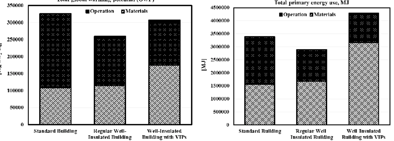
3.2. Total global warming potential
The VIPs have a significant environmental impact compared to conventional insulation (Figure 4). When applied to a low-energy building the contribution of VIPS results in a slightly higher GWP than a low-energy building with conventional insulation. Still, it has a lower GWP than a standard building. Regarding the primary energy, the VIPs don’t serve their purpose. Although the energy consumption is lower with a well-insulated building with VIPs the total primary energy was significantly higher compared to both building types.
Figure 4 GWP (left) and PE (right) of the material production and operational energy of the
15 3.3. Sensitivity analysis of VIPs
To investigate if the results are unique for this specific type of VIP that was chosen for this study a sensitivity analysis was performed where four types of VIPs were compared. The sensitivity analysis showed that there was a difference of 11 % in GWP and 12% in PE (Figure 5). The GWP is still higher but it there are measurable differences which indicate potential improvements.
Figure 5 The sensitivity of different VIP producers on the GWP of the scenarios.
3.4. Potential improvements
VIPs are competitive alternative for insulating buildings by saving valuable living space area. There is, however, a need for reducing the environmental impact. The GWP and PE of VIPs are mainly contributed by the energy intense core material which is made of silica fume [45]. A thin concrete façade panel which consists of VIPs made of recycled or an alternative core material could potentially have a positive effect on the environment. An investigation of the production process at the factory is also a potential improvement strategy.
17
4. Climate impact and primary energy of thin façade
solutions made of reactive powder concrete
Over the last 15 years, new materials have been developed that drastically reduce the thickness and weight of precast façade elements. This is accomplished by eliminating the minimum concrete cover thickness through the use of non-corrosive reinforcement in combination with ultra-high performance concrete (UHPC). The characteristics of UHPC are the high compressive strength and good durability properties. However, one concern with UHPC is that it contains a high amount of Portland cement clinker. As a drawback, this may not be considered as environmentally friendly. Paper II investigates the environmental performance of a new type of façade solution developed within the EU project SESBE. The solution is a precast sandwich element made of two thin reactive powder concrete (RPC) panels, a type of UHPC which includes a high amount of SCMs, and carbon fiber grid reinforcement. The RPC in this study was shown to have high mechanical and durability values, especially concerning chloride ingress.
Both Paper I and Paper II analyzes the environmental impact of a new type of thin concrete façade solution, but Paper II focuses on the concrete panels and the material production stage of the life cycle.
4.1. Method
The GWP and PE of the production of the materials were analyzed through LCA in accordance to EN 15804 in three steps.
1. Analyzing 1 m3 of concrete mix design.
2. Applying the mix designs in the chosen concrete panel solution and analyzing 1 m2 of concrete panel.
3. Applying the concrete panels in a context of a sandwich element and analyzing 1 m2 of sandwich element with a thermal resistance at 6 m2.K/W.
Finally, a comparative analysis was performed on different insulation and reinforcement materials.
4.2. Selected mix designs and components
Two types of RPC mix designs, RPC-3 and RPC-4, were analyzed. The main difference between the mix designs is that RPC-4 has a higher FA content and a lower compressive strength. The RPCs were compared with a regular concrete for façade applications and a regular UHPC without FA content. The mix designs are illustrated in Figure 6. The mix designs were then applied in façade panels as shown in Table 1.
18
Figure 6 Concrete mix design of the RPCs and the references in volume fractions.
Table 1Dimensions and reinforcement of the concrete panels.
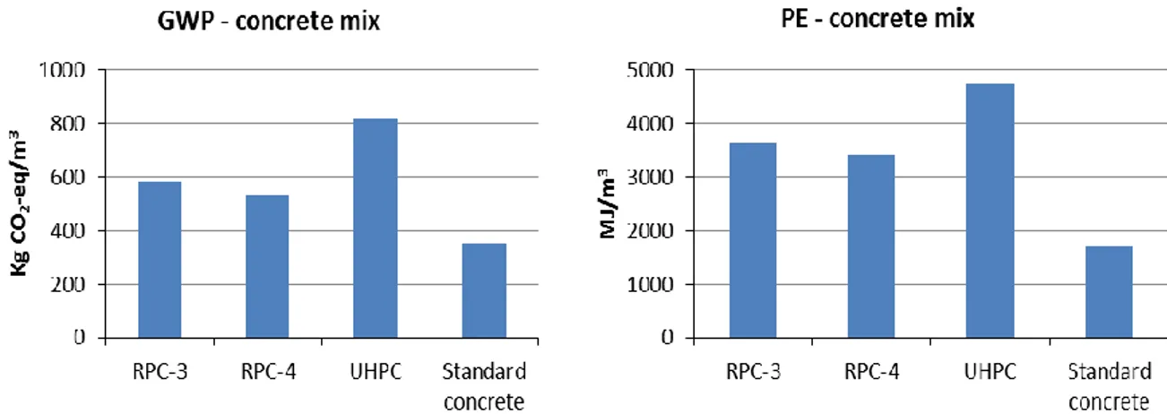
4.3. Environmental impact of mix designs
The RPCs have a GWP and PE that is between UHPC and standard concrete (Figure 7). They have a ca. 30 % lower GWP than UHPC but with a similar compressive strength that differs maximum 12 %. The environmental impact of this type of UHPC is lowered through material efficiency. However, it is still high compared to standard concrete and needs to have a RC structure with a cross-section area that is thin enough in order to have a lower GWP.
Concrete panels
Properties RPC-3 RPC-4 UHPC Standard
concrete Panel thickness [mm] 20 20 20 80 Reinforcement type
Carbon grid Carbon grid Carbon grid Steel bars Reinforcement
details
19
Figure 7 GWP (left) and PE (right) of the concrete mix designs.
4.4. Environmental impact of concrete panels
When applied in a concrete panel together with reinforcement the RPC mix shows a significantly lower GWP compared to standard concrete (Figure 8). However, the carbon fiber grid is energy intense to produce which increases the total GWP to 67 % of the panel made of standard concrete. The energy intensity of the carbon fiber grid is shown in the PE results which are higher for the UHPC and RPC panels.
Figure 8 GWP (left) and PE (right) per square meter of façade panel.
4.5. Environmental impact of a hypothetical sandwich element
Expanded polystyrene, EPS, was chosen as the insulating core material between two concrete panels. The chosen thermal resistance is 6 m2.K/W which in this case equals
an insulation thickness of 220 mm. This can be considered to be a well-insulated wall. The sandwich element with RPC shows a 27 % reduction in GWP compared to standard concrete (Figure 9). However, the PE of the RPCs and the UHPC is still high due to the carbon fiber grid although the gap has been reduced. The EPS has a significant contribution to both the GWP and the PE.
20
Figure 9 PE (left) and GWP (right) per square meter of facade element.
4.6. Improvement potentials
The façade solution with RPC is a potential environmentally sustainable alternative to standard concrete sandwich elements, which also increases the living space area. The durability of the material suggests that it could have a long service life and thereby a decreased maintenance demand. However, the carbon fiber grid is energy intense to produce and finding ways to reduce the weight of carbon fiber grid per panel or exploring alternative materials could further reduce the environmental impact. The insulation does also have a significant environmental impact on the sandwich panel. This could be potentially reduced through alternative insulating materials.
21
5. Climate impact optimization of slab frame bridges
The Swedish Transport Administration (STA) has concluded that greenhouse gas emissions from construction, operation and maintenance of the infrastructure must be reduced in order to reach national and global climate goals. The GHG emissions from infrastructure are to a great extent related to the production of construction materials [46]. Paper III investigates the potential to reduce the climate impact of a common type of concrete bridge in Sweden. The analysis is carried through by using easily implemented climate impact measures that are solely based on current norms and regulations as well as existing materials and technology. This project was carried out through collaboration with the industry, STA and WSP Group.
The aim of the study was to describe potential climate impact improvements in concrete bridges though easily implemented measures of the best available technology.
5.1. Selection of study case
The slab frame bridge was identified as the most common bridge type in Sweden. This type of bridge is suitable for industrial and serial construction with short span lengths typically less than 20 m and low geometric complexity. In order to investigate how different measures affects the climate impact an inventory of 6 slab frame bridges were collected from the project partners [47]. Figure 10 shows the typical design of the slab frame bridge. The chosen bridges are made of ready-mixed concrete and carbon steel reinforcement bars.
Figure 10 Design and parts of a slab frame bridge.
5.2. Method
Two categories of CO2 reducing measures have been chosen; material and design
related measures and construction related measures. These measures have been identified through a task group with experts within the field and are the following.
22 Material related
Concrete
Different cement suppliers are compared. The degree of SCMs is varied in the binder ranging from 0 % to 35 % where the maximum content is limited by the specific bridge and the application standard for concrete. Also different strength classes are compared where the strength class in the construction drawings is lowered to the minimum strength class according to the application standard for concrete.
Reinforcement
Suppliers from different parts of the world are representing measures related to scrap input, energy use in production and transportation. The reinforcements are ranging from locally produced low-CO2 scrap steel to
unknown steel which represent the global market with a high amount of virgin steel and long transport distances.
Design and construction related
Design
The structure is optimized where the cross-sectional area of the structure is reduced by increasing the amount of reinforcement. Additionally aesthetic effects are investigated and discussed.
Construction
Different construction methods are discussed.
All of these measures are related to a reference scenario which in this study is based on information from STA. In this way, the measures can be related to the demands set by STA. Most importantly is that the measures suggest a span going from worst case to best case according to the choices made in this study. This shows the potential impact of each type of measure.
The measures used in this study follow today’s regulations except for concrete which is investigated based on research by Thomas Concrete Group. This concrete measure is marked with “TCG” and contains 35 % slag for all exposure classes used in this study.
The CO2 reduction potentials are calculated mainly by collecting EPDs that follow EN
15804 and in some cases by gathering information from the LCA database ecoinvent 3. The functional unit is one concrete slab frame bridge. Only the material production stage, corresponding to A1-A3 in Figure 1, is included.
5.3. Material related CO2 reducing potentials in slab frame bridges
There is a great potential to improve the climate impact potential of slab frame bridges. Tables 2 and 3 present the reduction potential of each measure including a combination of measures for concrete. There it can be seen that most reduction potential can be achieved through clinker lowering measures and choosing a
23
reinforcement which is made of scrap and electricity with a low fossil content. The latter is a very easily implemented measure which has the potential to reduce the total climate impact by 27 % compared to the STA scenario without measures. The reinforcement gives variations from -27 % up to +46 %. When combining the concrete measures such as cement supplier, cement additives and strength class there is a potential to lower the climate impact by up to 27 %. Each measure has a large variation in climate impact. When adding up all the measures there is a potential to halve the climate impact compared to the STA scenario. But there is also a potential to increase the climate impact potential with the same number. This could be the case when making “the wrong” choices.
Table 2 Climate impact of individual measures.
Climate impact
Measure Average Max Min
No action* 0 0 0 Cement - supplier lowest -7% -6% -8% highest 13% 14% 11% Alternative binders slag 20% -10% -8% -10% fly-ash 20% -10% -8% -11%
slag 35% (fully or partly) -13% -12% -15%
fly-ash 35% (fully or
partly) -13% -13% -15%
slag 35% (fully, according
to TCG**) -19% -16% -21%
Reinforcement - supplier
low -19% -15% -27%
European average -6% -5% -9%
unknown origin 33% 46% 26%
Table 3 Climate impact of combination of measures.
Combination - concrete Average Max Min
min cement, max SCM, min concrete
class -22% -17% -27%
min concrete class, max SCM -15% -11% -18%
min cement, max SCM -19% -17% -22%
Measure - lowest possible (to
standard) -41% -33% -48%
Measure - highest possible (to
24
5.4. Impact of design and construction related measures
The cross sectional area of a structure with a fixed cover thickness can be reduced or increased by changing the amount of reinforcement. In this case, a reduction of cross sectional area by increasing the reinforcement amount reduces the GWP of the structure. This is due to the larger amounts of concrete that is reduced in comparison to the increased reinforcement. However, this GWP reduction highly depends on the GWP level of each material. If the reinforcement has a high GWP compared to the concrete the reduction could be insignificant.
The aesthetics can have a positive effect on the GWP when it is incorporated in the structural design. The opposite can be realized for example when adding concrete to create surface effects.
25
6. Impact of SCMs on service life and global warming of
concrete bridges
One of the main durability problems of RC structures is chloride induced corrosion and due to the long costal line and use of de-icing salt Sweden is no exception [34]. In order to protect the steel reinforcement from corrosion and reach the target design service life, a certain cover thickness is needed. The durability and service life of concrete structures is, at present, regulated by national requirements which besides a minimum cover thickness also put constrains on SCMs. However, the regulations do not consider the durability performance of SCMs. This means that concrete with SCMs is assumed to have the same durability performance as concrete with OPC only. As previously mentioned, numerous of studies have already established that there is a difference in durability between SCM and OPC concrete. Paper IV evaluates the GWP of concrete infrastructure parts exposed to chlorides considering the durability performance of SCM.
6.1. Comparing performance based cover thicknesses with regulations Two cover thickness approaches are evaluated in this study where a service life of 100 years, in accordance with Eurocode, is the target. The first is based on current regulations (prescriptive) and the other considers the different performances of SCMs and is based on a study. The performance based approach is carried out in two methods; one that has the same cover thickness as the current regulations (performance CT 45 mm) and one where a service life of 100 years is targeted and the cover thicknesses for each individual case and concrete is calculated accordingly (performance SL 100 years).
6.2. Selection of case study and concrete mix
In order to analyse the GWP of RC structures exposed to chlorides, two cases have been selected that meet this criterion. A bridge edge beam has been chosen to evaluate the concrete exposed to de-icing salt, which is XD3 according to EN 206 [27]. Another reason why an edge beam was chosen is because of its noted durability and repair cost issues. The second case that was chosen is a bridge pier which is exposed to chlorides from a marine environment. These are the XS classes in EN 206 [27]. Further details about the cases can be found in Paper IV.
Five different concrete mixes with and without FA and GGBS content were compared and analyzed, see Table 4. The mix designs were developed within a STA project.
26
Table 4 Mix designs for comparison.
Mix w/b [kg/mOPC 3] [ kg/mFA 3] [ kg/mGGBS 3] Aggregates, crushed [ kg/m3] Aggregates, natural [ kg/m3] 1 0.40 353 69 844 863 2 0.40 425 846 864 3 0.40 340 85 842 861 4 0.40 302 123 836 854 5 0.40 350 87.5 928 759 6.3. LCA approach
The GWP is calculated in accordance to the harmonized European standard for EPDs for construction product, EN 15804 [28]. The life cycle stages that are included in the LCA are the material production stage and the use stage which in this case involves product replacement. The replacement is in turn determined by calculating how many product life cycles it takes to reach a service life of 100 years. In order to include the life cycle of concrete exposed to chloride the ERFC (error function complement) model was used, which is based on the frequently used solution Fick’s 2nd law of diffusion in an infinite half-space. The purpose is to calculate the service
life of reinforced concrete with a specific cover thickness by using a reference scenario which in this case is the research of Luping and Löfgren [43]. Since the chloride profile is fixed for each concrete mix then the time, t, is calculated through an equation between two cover thicknesses (equation (1)). For example if mix 1 has a cover thickness at 45 mm and it is known that the corresponding service life will be 100 years then a cover thickness of 40 mm will have a service life at 𝑡 years.
𝑡 = 𝑡𝑟𝑒𝑓∗ (𝑥𝑥 𝑟𝑒𝑓)
2
(1)
Where:
𝑡 = service life of concrete with 𝑥 cover thickness [year]
𝑡𝑟𝑒𝑓 = service life of reference concrete with 𝑥𝑟𝑒𝑓 cover thickness [year]
𝑥 = cover thickness of concrete [mm]
27
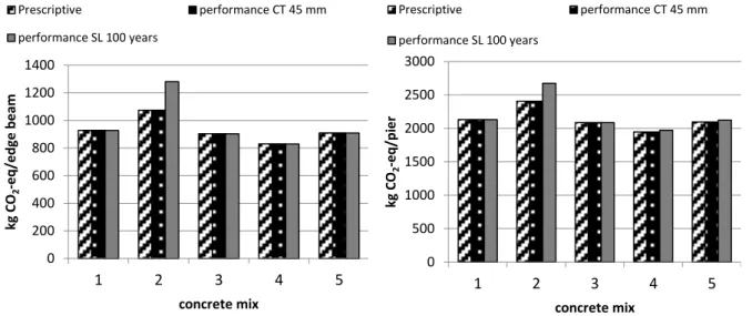
6.4. The influence of SCM on GWP of a bridge edge beam and a pier
The LCA of the production stage shows that there is a significant increase in GWP for mix 2 (OPC concrete) due to an increase of cover thickness for the performance SL 100 method (Figure 11). When adding 16 % FA (mix 1) the cover can be reduced to 45 mm which results in a decrease in GWP at 28 % regarding the bridge edge beam. However, this does not include the effect of the durability. When the use stage is included in the LCA the results show the consequence of a decreased cover thickness (Figure 12). This time mix 2 with a cover thickness at 45 mm will have more than a doubled GWP over 100 years compared to if it had a cover thickness at 70 mm. This means that OPC concrete at 45 mm will need more repair and replacement. The results show that adding FA or GGBS to the concrete mix not only reduces the GWP due to lower clinker content but also due to a longer service life. Figure 11 and Figure 12 also illustrate the effect of using standards in LCA that do not distinguish between the durability of OPC and SCM.
Figure 11 GWP of the edge beam (left) and pier (right) during the material production stage.
0 200 400 600 800 1000 1200 1400 1 2 3 4 5 kg C O2 -e q /e d ge b e am concrete mix Prescriptive performance CT 45 mm performance SL 100 years 0 500 1000 1500 2000 2500 3000 1 2 3 4 5 kg C O2 -e q /p ie r concrete mix Prescriptive performance CT 45 mm performance SL 100 years
28
Figure 12 GWP of the edge beam (left) and pier (right) during the material production and
use stage.
6.5. Impact of SCM on service life design and GWP
Based on this study a relation between climate impact, service life and cover thickness of a 1 m bridge pier with a 1 m diameter was established (Figure 13). This relation is calculated through a performance based approach including an OPC concrete and a 20 % FA concrete alternative. The reinforcement is excluded from the analysis but can be added to the results for the total GWP of the structure.
Figure 13 shows that when designing a pier to last 100 years, a cover thickness will be obtained depending on the FA and GGBS content. A 20 % FA concrete, as in this case, might decrease the cover thickness from 80 to 45 mm, which is a total decrease in volume by 12 %. This will result in a decrease in GWP by 27 % compared to OPC. The GWP can also be calculated the other way around by starting from a required cover thickness. For example, if the cover is 50 mm the service life for OPC will be 40 years while for 20 % FA it will be 130 years. This results in a GWP difference at 75 %.
0 500 1000 1500 2000 2500 3000 1 2 3 4 5 kg C O2 -e q /e d ge b e am concrete mix Prescriptive performance CT 45 mm performance SL 100 years 0 1000 2000 3000 4000 5000 6000 7000 8000 1 2 3 4 5 kg C O2 -e q /p ie r concrete mix Prescriptive performance CT 45 mm performance SL 100 years
29
Figure 13 The relation between GWP, cover thickness and service life in concrete with OPC
and FA. 0 20 40 60 80 100 120 140 0 2 4 6 8 10 12 14 16 0 50 100 150 200 250 mm kg CO2 -e q /y e ar years
GWP OPC (left-hand scale) GWP 20%FA (left-hand scale)
31
7. Discussion and conclusions
The environmental impact of new and existing solutions for concrete structures was evaluated in this research with focus on material efficiency and durability. Product specific LCA studies were carried out on concrete structures with SCMs and the effect of durability of different mix design alternatives on the environment was evaluated. The following discussions and conclusions of this research are presented.
7.1. Major Conclusions
Environmental performance of low-energy buildings with vacuum insulation panels (Paper I)
Thin exterior walls increase the living floor area and they could be constructed either by having thin structural elements or by using insulation with a low thermal conductivity. This research is focused on the thermal insulation where VIPs were used. The purpose of low-energy buildings is to reduce the energy consumption and thereby lower the environmental impact. When analyzing the production stage and the operational energy the results show that the VIPs contribute to a significant share of the total environmental impact of the building. And even though the purpose was to lower the operational energy the material demands a high amount of energy during the production that the total primary energy will instead increase compared to the reference buildings.
A sensitivity analysis showed that there is a measurable difference between different VIP producers. This indicates that there is a possibility to reduce the environmental impact in the factory processes. The main environmental impact of the VIPs is derived from the core material and using recycled core materials could improve the durability. However, this is also related to thermal performance and further investigation is therefore needed.
Climate impact and primary energy of thin façade solutions made of reactive powder concrete (Paper II)
Although RPC contains a large amount of cement clinker and has a high global warming potential and primary energy per cubic meter, applying it in a 20 mm thin textile reinforced panel could reduce the environmental impact. The GHG reduction potential is 33 % when the RPC is applied in panels. It was also shown that it is possible to reduce the environmental impact of UHPC and yet obtain a high compressive strength with the use of SCMs.
Carbon fiber grids have a high environmental impact compared to steel reinforcement bars even though the weight is less. This could be reduced by using an alternative reinforcement or by minimizing the weight of the carbon fiber grid.
![Figure 1 Modular division of life cycle stages according to EN 15804 [10]](https://thumb-eu.123doks.com/thumbv2/5dokorg/5509074.143546/20.892.101.790.130.446/figure-modular-division-life-cycle-stages-according-en.webp)