New Automated Composite Manufacturing Process:
Is it possible to find a cost effective manufacturing method with the use of robotic
equipment?
Jan Erik Lindbäck 1,3, Andreas Björnsson 2,3, Kerstin Johansen 3
1
Saab Aerostructures, Linköping, Sweden
2
Compraser, Linköping, Sweden
3
Linköping University, Department of Management and Engineering, Division of Manufacturing Engineering, Linköping, Sweden
ABSTRACT
The use of carbon composites has continuously increased in the commercial aircraft industry due to more challenging weight targets which is one way to handle the environmental requirements to lower the CO2 emissions. One type of aircraft structure component made at Saab Aerostructures is long and slender U-sections manufactured in carbon composites. The manufacturing is performed by manual layup of material. These U-sections are selected as an illustrative case in order to discuss possibilities for an automated manufacturing process with the aim to reduce cost. A literature review of different existing technologies have been performed and compared with the industrial front at Saab Aerostructures. Automated Tape Laying (ATL) and Automated Fibre Placement (AFP) are the two dominating automation methods, of today, for aircraft prepreg manufacturing. Both methods are heavy investments for small to medium size composite manufacturers. Analysis in the case has shown that the selected component cannot be automated with these two methods due to design constrains. The paper suggests that another automated method with a cutting machine in combination with an industrial robot with a vacuum gripper, is selected for further work. The proposed pick and place process is also assumed to reduce the material waste.
Keywords: prepreg, automation, aircraft, ATL, AFP, pick and place
1. INTRODUCTION
The use of composite material in the aircraft industry has constantly increased over the years and the new Boeings 787 Dreamliner has about 50% of the structural weight made of composite [1]. Grandine [1] describe that both fuselage and wing structure are made from carbon composite, see Figure 1. Saab Aerostructures is a design to build, Tier 1 supplier, of carbon composite cargo doors to the Boeing 787 and to the Airbus A320 aircrafts. Apart from being supplier to Airbus and Boeing, Saab Aerostructures also make
composite parts to the Gripen fighter and to space applications. The predominant composite material process at Saab Aerostructures is to use carbon prepreg tape which is pre-impregnated unidirectional carbon fibers mixed with uncured epoxy resin. The prepreg, with a thickness down to 0.13 mm, is laid up ply by ply in different directions forming a laminate. Opposite to mechanical milling of a metallic component, where material is removed to get the final shape, the prepreg process is to add material ply by ply in specific fibre directions to get a weight optimized structure with strength and stiffness constrains fulfilled.
Typically, for aircraft design, the fiber directions 0°, 90°, 45° and -45° are used. A common prepreg manufacturing process is manual layup ply by ply directly on the mold tool to the final shape. After the layup of all plies, the laminate is cured in an autoclave, typically with 6 bars overpressure in 180° C. Anoth er, more automated process is when the geometry of the component allows the laminate to be laid up flat to its full thickness and formed to the final shape in a secondary process step prior to cure. This is for example performed on the wing spars for the Gripen fighter. The reason to use this two-step process with an additional forming step is lower manufacturing cost and a more stable process.
There are also automated alternatives [2] to the manual layup methods described above. Automatic Tape Laying (ATL) and Automatic Fibre Placement (AFP) are two processes commonly used for aircraft prepreg composite manufacturing. Robot pick and place of prepreg plies is another possible automation method. The purpose of this paper is to analyze automated manufacturing processes for composite prepreg manufacturing, like ATL, AFP and “pick and place” as alternatives to a specific ongoing manual layup process performed at Saab Aerostructures today. The reason for evaluating possible automated solutions is to reduce the labor cost with a remained or improved quality level. Furthermore, the prepreg material waste is challenged to be reduced. The specific ongoing manual layup process is described as a case study in this paper. The studied component is today manufactured manually because no automated process has been found applicable for this type of design of a long and slender U-section with internal thickness variations. This paper will also propose further work for introducing a new automated process for the component.
2. METHODOLOGY
This case study is performed with an action research approach [3]. The research group has direct access to, and one person has own experience, within the prepreg manufacturing process. The process issues have been continuously integrated to the company’s steering group and manufacturing department. To identify the research front in the area a literature review of different existing technologies have been performed and compared with the industrial front in the company. Furthermore, meetings and observations at the company were performed with a qualitative approach [4].
3. THE ATL AND AFP PROCESSES
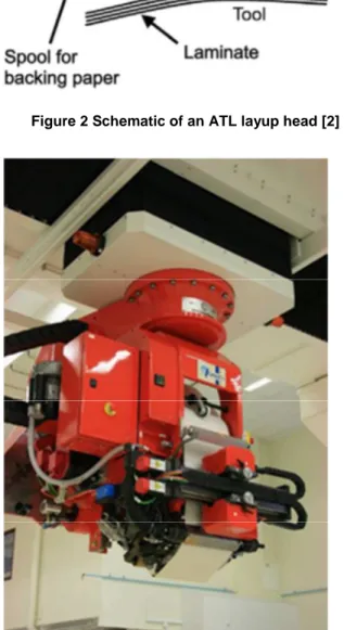
The ATL machine head, illustrated in Figure 2 and Figure 3, can layup prepreg tape with a tape width of 300 mm, 150 mm or 75 mm. The prepreg-roll raw material is charged to the ATL-head and prepreg will be laid up ply by ply in different directions forming a laminate. According to Lukaszewicz et al. the ATL-head is normally mounted in a gantry or a column system [2].
Figure 2 Schematic of an ATL layup head [2]
Figure 3 Image of Saab Aerostructures ATL, supplied by MTorres, charged with 300 mm prepreg
Due to experiences in the manufacturing process at Saab Aerostructures the ATL will provide the highest lay down rate (kg/hours) when laying up prepreg on large flat surfaces where the numbers of starts and stops are few, preferably also without any ply drop off zones. A ply drop off zone is the transition zone between two different laminate thicknesses where one or several plies are dropped off. However, for aircraft structure ply drop off zones are necessary for weight
optimization and very few components are flat. It is difficult to predict the ATL lay down rate capacity in general, because own observations identified that the lay down rate will depend of the complexity of the component to be manufactured. Therefore, structures with a final shape other than flat, preferable use an ATL-process followed by a forming operation. However, slightly double curved structure and single curved structure can be laid up directly on the mold tool with an ATL. The limitations in double curvature for the ATL are linked to the prepreg material width. The wider material, the less curvature can be draped without having buckles and induced wrinkles on the final layup. The above statements about ATL are based on experiences from Saab Aerostructures.
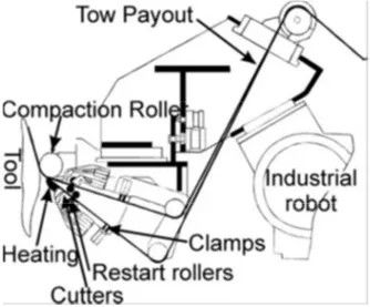
According to Lukaszewicz et al. [2] AFP is a process similar to ATL but with the main difference that the prepreg tape material is slit into several more narrow strips, called tows. An AFP tow width can be 12.7 mm, 6.3 mm or 3.2 mm. To get lay down rates comparable with ATL several tows are laid down simultaneous. The AFP machines can be supplied to lay up different number of tows, where 16 or 32 tows are two common sizes for an AFP-head as shown in Figure 4 and Figure 5. Note that the prepreg material is running to the AFP-head via the black tube as shown in Figure 5. The weight of the prepreg tape material rolls will therefore not affect the AFP head during accelerations and retardations.
Figure 4 Schematic of an AFP layup head [2]
Figure 5 Image of a Corilois AFP head mounted on an industrial robot. (Picture courtesy of Corliolis
Composites.)
As previously mentioned, one drawback with ATL is the limitation in laying up double curved structure with the wide material. AFP, on the other hand, makes it possible to lay prepreg tape directly on a double curved complex shaped mold tool without distorting the material [2]. Each tow can be driven and cut separately [2]. Another difference between ATL and AFP is that AFP performs all cuts perpendicular to the fibre direction. This will reduce waste since no material have to be scrapped between stopping one ply and starting the next. One drawback, however, is that there will be a saw tooth shape contour for most edges in the AFP. For an external contour later to be trimmed this is not an issue, but for an internal ply drop off zone or a net shape contour this have to be regarded by the stress and the design engineers. An example of how a saw tooth shape can look like is shown in Figure 6. Net shape is an expression for plies at the edge of a laminate not mechanically trimmed after cure.
Figure 6 Illustration of the saw tooth shape of an AFP ply drop off zone at 45° direction
The two automated production processes, ATL and AFP are excellent described in Lukaszewicz et al. [2] and summarized as: “ATL offers high productivity and
reliability for simple and low complexity components while AFP improves on ATL by allowing direct layup of more complex components. In addition, material waste is reduced for AFP compared to ATL”. The summary for ATL corresponds with the experience from Saab Aerostructures, in possession of an ATL gantry machine supplied by MTorres. ATL gives high producability for large flat non-complex structure but a drop in efficiency when complexity, like thickness variations, increases.
Grant et al. [5] have discussed the topic of reducing the cost of automation for the aerospace composite industry at a SAMPE symposium in 2003. Although it is almost ten years old some of the recommendations are still interesting to highlight. One is a wish for “Lower Complexity Machines” stating that you do not have to buy a machine that can do more than you need. Another similar recommendation is to suggest “Custom Automation” which can be explained by having custom made work cells for production of specific composite components [5]. A few years later (2006) the same author discussed cost for the automated composite processes and found that there are a few automated processes available, ATL and AFP, and that they are very expensive [6].
Later, Marsh [7] has focused on describing the revolution of AFP for high-volume production of complex aerospace structures. He also mentions that AFP is commonly used for the Boeing 787 Dreamliner, A350 XWB and Bombardier C-series.
4. THE ROBOT PICK AND PLACE PROCESS
The use of industrial robots in combination with pick and place technique is here regarded as the third automated composite production process. The current state of the art in robotic pick and place of composite materials is much less mature compared to AFP and mainly applied in research and development projects; according to an internal COALESCE report by Sterk [8]. COALESCE (Cost Efficient Advanced Leading Edge Structure) is a project within the European Union 7th Framework program where Saab Aerostructures have been one of the participants. Within the COALESCE project a comparison between AFP and a robot pick and place was performed. The pick and place alternative was identified to be more favorable than AFP for the selected component. A robot pick and place cell was developed and a physical demonstration was performed. According to Sterk [8] the required tolerances were difficult to reach with robot pick and place and an estimated time to lay up one single ply was between 75 to 100 seconds. One feature that complicated the COALESCE scope was that the robot was intended, not only to pick and place the plies but also, to drape the prepreg fabric directly on a double curved curing tool. Another difference from the ATL and AFP processes described above is that this pick and place study was performed with prepreg fabric and not with unidirectional prepreg tape.
Angerer et al. [9] describe another pick and place example for composite material, which was performed for dry fabric and not for prepreg. A pick and place demonstrator cell was developed, see Figure 7. An end-effector gripper of vacuum type with separately controlled vacuum valves was developed and tested. Reinhart et al. [10] has also developed a huge end-effector with the ability to handle single plies up to 2250 mm x 1200 mm.
Figure 7 Simulation of the process in KUKA.Sim Pro using the process layout including a material delivery system, a single-ply cutter with conveyor, an industrial robot with a gripping end-effector and
a tray storage system [9]
A variant of the pick and place process was performed as early as 1996 by Buckingham et al. [11]. A demonstrator was made with a cutting machine and a gantry robot system integrated to cut prepreg and pick and place it on a mold tool. Also mechanical forming by the robot was implemented. A conclusion from Buckingham et al. [11] was that that the demonstrated process in the correct application was economically viable.
Compared to ATL and AFP the research related to pick and place [8] [9] describes a less mature process. Even though both are demonstrated by full scale demonstrators no such production method has be found so far in the literature for any aircraft serial production application. Furthermore, a robotic pick and place solution demands suitable end-effectors [9] [10].
5. A DESCRIPTION OF THE CASE STUDY WITH THE MANUAL LAYUP PRODUCTION PROCESS
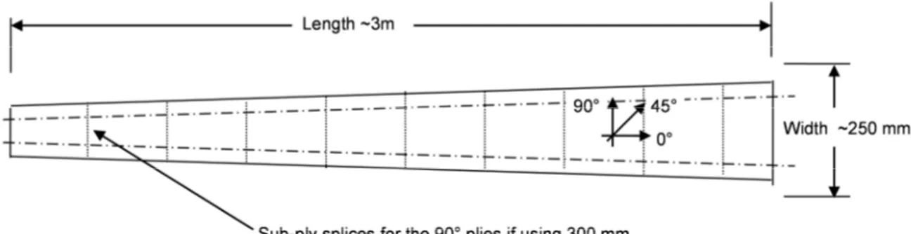
There is an ongoing production line with a manual layup prepreg process at Saab Aerostructures that is challenged for cost reduction. This production line will be used as a case study example in this paper. The design of the component is shown in Figure 8.
Figure 8 A sketch of the laminate of the component consisting of four plies of prepreg tape. Not to scale
The final shape of the component is U-shaped. The current manufacturing method is to lay up four plies manually and then vacuum form the flat laminate to a U-section on a forming tool. The production rate is more than 30 parts per day.
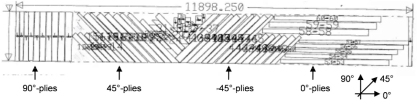
The prepreg material is stored in a freeze on 1500 mm wide rolls with backing paper on one side of the prepreg and plastic film on the other side. The prepreg tape material is cut to the correct ply dimensions in a cutting machine, labeled and moved to the layup station where the flat laminate is made by manual layup. There is only one ply in the 0°-direction but three sub-plies in the 90°-direction and two sub-plies for the 45°- and -45°- directions respectively due to the raw material width of 1500 mm, se Figure 8. The general production flow is further clarified in Figure 9 and in the following bullets. Prepreg tape material is nested and cut for eight components at the same time to minimize material waste. However, there is a considerable material waste in the cutting operation, as illustrated in Figure 10. The 1500 mm prepreg material is attached to a 12 m long cutting table and all rectangular sub-plies are cut to shape.
Figure 9 The current cutting and layup process flow for the case study components
• Prepreg material is stored in the freeze.
• The 1500 mm wide prepreg material is defrosted and charged in a cutting machine
• A cutting program is selected and cutting is performed
• The cutting machine will automatically label all plies • The plies are manually picked from the cutting table. • They are sorted and transported to storage racks at
the layup stations
• The protecting backing paper and plastic film is removed from the prepreg. Flat layup is performed on templates. Inspection of the layup is performed with operator self-control during layup.
• The completed laminate is manually moved from the layup table to the forming station together with the template.
Cutting Labeling
Sorting Manual
Layup Transport
Figure 10 An image of the prepreg material nest in the cutting machine for eight case study components. Nest file provided by Saab Aerostructures
6. COST FOR PREPREG COMPOSITE MANUFACTURING
It is common knowledge that parts made of carbon composite are expensive. High performance carbon composite material has been used for space and military aircraft for decades. The commercial aircraft industry has increased the level of carbon composites over the years; see Figure 1. Saab Aerostructures have participated in several bidding phases on aircraft work packages with composite content for more than ten years. Both for built-to-print work packages where only manufacturing is included, and for design-to-build work packages where design and stress responsibility also is included. The Saab Aerostructures view is that the costumers focus is more and more on having a low composite manufacturing cost.
A study within Cost Modelling for Manufacturing of Aerospace Composites was performed by Ma in 2011 under the supervision of Dr Essam Shebab at Cranfield University [12]. The scope was to develop a cost model for composites manufacturing based on an industrial survey for identifying cost drivers for composite manufacturing. The survey was made among five manufacturing companies of aircraft components in China. A result from that study was that 42% of the total manufacturing cost was labour cost and another 42% was material cost. This result was based on carbon composite materials and manual layup. This study was focusing on dry fibres with an injection process instead of a prepreg process. It is likely to assume that the dominant cost driver’s; labour and material would be of a similar magnitude for prepreg.
7. ANALYSIS OF COST REDUCTION AREAS
Three different key areas from the survey in the Cranfield study [12] are explored below;
- Reduce cost by using less expensive material - Reduce material waste
- Reduce labour cost
To reduce cost by using another less expensive composite material
For aircraft primary structure like wing skins, wing spars, fuselage frames, etc. the OEM’s, like Airbus and Boeing,
more or less dictates what material to be used. Sometimes there is a list with a number of materials to choose from, but for primary aircraft components all materials are of equal high performance and high price. For secondary aircraft components like fairings there might be alternative materials to carbon composite prepreg material to choose from. It will then be a trade-off between cost and weight. The case study is a subcomponent of a primary aircraft component, so the material and process is well defined and cannot be challenged.
To reduce the material waste per part
The composite material waste can either be in the cutting phase or in the trimming phase after cure. The plies for the component in Figure 8 are nested, in an optimum position to minimize scrap on the 1500 mm prepreg material. It is however clear that there will be scrap in the cutting process, see Figure 10. The material waste will also differ considerably between manual layup, ATL and AFP where as previously mentioned AFP gives very little material waste.
To reduce the labour cost per part.
For manual layup, the labour cost is a large part of the manufacturing cost based on Saab Aerostructures estimates. Manual layup aid in form of laser projection or Mylar templates of where to place the plies is used to assist the operator but all plies are still laid up by hand. For large components usually two operators are working in pair on the same layup. Automation with ATL or AFP will significantly reduce the operator cost. Layup in the ATL is 3-4 times faster than manual layup according to a Saab Aerostructures analysis. The tough requirements on inspections during layup will however require manual attendance even if ATL or AFP is used. The ATL operator at Saab Aerostructures also visually inspects all layup plies for gaps, overlaps and wrinkled fibres according to the costumer quality requirements. The lean principles are up and running at Saab Aerostructures composite shop and it will constantly improve the efficiency by small steps, but in order to take larger steps or kaikaku, in lean terminology, it is desired to challenge the production process efficiency on a higher level. A way to reduce the labour cost per
produced part is to increase the level of automation in the composite shop.
8. AUTOMATION WITH ATL OR AFP
ATL and AFP have a dominant position in automation of aircraft composite production, and the investment costs are still high ([2] [6] [7] and Saab Aerostructures experiences regarding ATL).
A robot mounted AFP is significantly cheaper to buy than a gantry unit ATL or AFP [2] However, still it requires a strong business case to finance a robot mounted AFP due to the high investment cost, according estimations at Saab Aerostructures.
Neither ATL nor AFP is possible to use for the selected component in this study, without changing the part design. For ATL the reason, without going into details, is the short ply lengths, not possible to layup in Saab Aerostructures ATL-machine. For AFP it is the saw tooth shape that will make the plies exceeding the current tolerance requirements. ATL or AFP would most likely be possible to use for the studied component, if a part design revision was performed. However, a design change may require a new stress test and other certification activities for the component, so it is not regarded as an option to automate the studied component neither with ATL nor AFP.
9. AUTOMATION WITH ROBOT PICK AND PLACE
To develop an automated process that replaces the manual layup process is not “technology of the shelf” and a further research is proposed. The technical proposal for the new layout is a cutting machine in combination with a robot pick and place cell that automatically cuts the prepreg material, pick the plies,
remove the backing paper, orient and place the laminate on a flat layup table in the correct position. This proposal, with a cutting machine and an industrial robot with special designed grippers, is very similar to the COALESCE study [8] and to the study made by Angerer [9]. Both of those studies have also been demonstrated in full scale, although only in a research environment. In our case, no forming will be performed, which will reduce the complexity.
The design of the grippers is believed to be the most challenging task. The prepreg material is a sticky material for which no suitable end-effector grippers, as of today, can be purchased, off the shelf. Several researchers recommend vacuum grippers for handling prepreg [10] [11].
Once a defined gripper solution is demonstrated successfully, the next task will arise; to design a gripper system to handle a large variety of ply dimensions. In Figure 8, the size of the plies which needs to be handled is viewed; the 0° ply is 3 m long and less than 250 mm wide. The 90° ply is divided into two sub-pl ies in Figure 8 but it can be split into several smaller plies as long as no fibres are cut. A suggestion is to use 300 mm wide ATL raw material. If so, sub plies in the 90° ply direction would then look like in Figure 11. Note that no fibre cuts are introduced. There are only additional splices along the fibres. As long as the gap and overlap requirements are within specifications the additional splices will not affect the structural strength. One hypothesis is that the material waste can be reduced for the 90°, 45°and -45° plies if using 300 mm wide material. This is shown in theory for the 90°-ply i n Figure 12 and is assumed to be valid also for the ±45°-plies.
Figure 12 A sketch of the components 90° ply with s ub-ply splices from the 300 mm material roll. Not to scale
The proposed solution for material waste reduction is, however, not obvious for the 0° plies which also mu st be considered when comparing material waste between different processes.
From the COALESCE prepreg pick and place example [8] it took a relatively long time, up to 100 seconds, to pick and place one ply. From a Saab Aerostructures point of view, this lay-down rate is not sufficient to compete even with the manual layup, performed today. The removal of the protecting plastic film did take a considerable time of these 100 seconds. For further work the removal of plastic film and/or backing paper, must be a faster process than demonstrated in the COALESCE project. One suggestion is to use the 300 mm ATL-material equipped with backing paper only and to not use plastic film. The removal of backing paper is another challenging task to be studied in future work. The general description of the proposed automated pick and place process is viewed in Figure 13 and described in the following bullets.
Figure 13 The proposed automated process flow for the case study component
• Prepreg material is stored in the freeze. • The 300 mm wide prepreg material is
defrosted and charged in the cutting machine • The second box illustrates the automatic
cutting and “pick and place” cell.
• The cell consists of a cutting machine and an industrial robot with special designed grippers
to handle prepreg plies of arbitrary dimensions.
• The robot will place the plies on templates similar to those used for the current process. • When the flat laminate is laid up the robot will
go to sleep and an operator will manually move the laminates to the forming station similar as for the current process. The operator will simultaneous visually inspect the laminates
10. CONCLUSIONS AND FUTHER WORK
It is identified that automation and reduced material waste are key parameters to reduce the manufacturing cost for composite manufacturing. The three different ways to automate today’s composite manufacturing in the aircraft industry – ATL, AFP and pick and place with industrial robots – have its strengths and weaknesses. ATL and AFP are the dominating methods for aircraft prepreg manufacturing, and both are heavy investments for small to medium size composite manufacturers. On the other hand, the pick and place with industrial robots is not as mature as the ATL and AFP processes. The performed study illustrate that there is not applicable to automate the existing manual layup process with either ATL or AFP. Furthermore, it is identified that it could be possible to reduce material waste, by using a robotic pick and place solution that is collaborating with a cutting machine. However, a new gripper end effector needs to be developed in order to support a new automated solution.
Further work will be conducted related to the grippers in on-going research projects. The performed study is in a sense very specific with the 10 mm overlaps between the plies. In case of a successful result of the future work on pick and place, the next step would be to compare traditional U-spar manufacturing between the pick and place method and ATL.
Freeze
Cutting and Robot Pick and Place Cell
Transport
Above, the sub-plies 1-10 are laid up in the 90°-di rection Left, the 300 mm wide prepreg material is shown with the cut sub-plies 1-3. Sub-plies 4-10 are not shown but will use the same principle
The blue and red colors on the laminate edges will illustrate how the sub-plies are rotated before layup.
In theory, if a shared cut line is used between the sub-plies zero material waste will be achieved for the internal sub-plies 2-9
11. ACKNOWLEDGMENTS
The authors would like to thank Swedish Foundation of Strategic Research (SSF) for its Mobility Foundation from industry to academy and professionals at SAAB Aerostructures.
12. REFERENCES
[1] Grandine, T.A., (2012). Surface Modeling for Composite Materials. [Online]. Available at: http://siag.project.ifi.uio.no/problems/grandine/ [June, 2012], Seattle
[2] Dirk H.-J.A. Lukaszewicz, Carwyn Ward, Kevin D. Potter. (2012). The engineering aspects of automated prepreg layup: History, present and future. Composites Part B: Engineering Volume 43, Issue 3, April 2012, Pages 997– 1009, Bristol
[3] Gummesson, E., (1991), Quality Methods in Management research, Sage, London
[4] Leedy, P., (1997), Practical Research: Planning and Design, Sixth Ed. Merril, An imprint of Prentice Hall, New Jersey
[5] Grant, Martin, (2003), Automated processing technology for composites: Current status and vision for the future, 48th International SAMPE Symposium, May 11-15, Sandy, Utah
[6] Grant (2006), Automated processes for composite aircraft structure, Industrial Robot: An internal Journal, Vol 33 Iss: 2 pp. 117-121, Sandy, Utah
[7] George Marsh, (2011) Automating aerospace composites production with fibre placement, REINFORCED plastics ,Volume 55, Issue 3, May–June 2011, Pages 32–37
[8] S. Sterk (2012), Manufacturing trials development & testing of double curved complex aerodynamic surfaces. An internal COALESCE Report
[9] Angerer, Ehinger, Hoffmann, Reif, Reinhart, Strasser, (2010), Automated Cutting and Handling of Carbon Fibre Fabrics in Aerospace Industries, 6th annual IEEE Conference on Automation Science and Engineering Marriott Eaton Centre Hotel Toronto, Ontario, Canada, August 21-24, 2010 [10] Reinhart, G. & Straßer, G. 2011, "Flexible
gripping technology for the automated handling of limp technical textiles in composites industry", Production Engineering, , pp. 1-6.
[11] Buckingham, R. & Newell, G. 1996, "Automating the manufacture of composite broadgoods", Composites Part A: Applied Science and Manufacturing, vol. 27, no. 3, pp. 191-200.
[12] Weitao Ma, 2011, COST MODELLING FOR
MANUFACTURING OF AEROSPACE
COMPOSITES CRANFIELD university, MSc by Research Thesis
![Figure 1 Materials in Boeing 787 Airframe [1]](https://thumb-eu.123doks.com/thumbv2/5dokorg/5454123.141435/1.892.101.768.871.1147/figure-materials-in-boeing-airframe.webp)