SKI Report 00:19
A Study of Defects which Might Arise
in the Copper Steel Canister
ISSN 1104-1374 ISRN SKI-R--00/19--SE
W. H. Bowyer
SKI Report 00:19
A Study of Defects which Might Arise
in the Copper Steel Canister
W. H. Bowyer
Meadow End Farm, Tilford, Farnham
Surrey. GU10 2DB. England
May 1999
This report concerns a study which has been conducted for the Swedish Nuclear Power Inspectorate (SKI). The conclusions and viewpoints presented in the report are those of the author and do not necessarily coincide with those of the SKI.
SUMMARY
A study has been conducted to identify the material and manufacturing defects that might occur in serially produced canisters to the SKB reference design.
The study has depended on cooperation of contractors engaged by SKB to participate in the development program, SKB staff, observations made by the writer over a five-year involvement with SKI, literature studies and consultation with experts.
The candidate manufacturing procedures have been described inasmuch as it has been necessary to do so to make the points related to defects. Where possible, the cause of defects, their likely effects on manufacturing procedures or on durability of the canister and the methods available for their detection are given. For ease of reference each section of the report contains a table which summarizes the information in it and, in the final section of the report, all the tables are presented en-bloc.
Contents
SUMMARY ...3
CONTENTS ...5
1. INTRODUCTION ...7
2. RESULTS OF THE STUDY...9
2.1. Castings of the load bearing liner in nodular iron. ... 9
2.1.1. Direct casting ... 9
2.1.2. Indirect casting...11
2.2. Continuous castings of OF grade copper ingots ...13
2.3 Copper tubes made by extrusion...16
2.4. Copper tubes made by the pierce and draw process ...18
2.5. Copper plates suitable for fabricated tubes of the relevant dimensions...21
2.6. Roll formed semi-cylinders in copper...22
2.7. Welded Tubulars...23
2.8. Electron beam welds...24
2.8.1. Linear Defects...24
2.8.2. Cavities ...26
2.8.3. Underfilling...26
2.8.4. Cracking ...27
2.8.5. Gun Discharge Defects ...28
2.9. Copper forgings for lids and bases. ...29
3. REFERENCES ...32
1. Introduction
After many years of development effort SKB1, 2 have made considerable progress towards the definition of a design and a manufacturing procedure for a canister to be used for deep geological disposal of nuclear waste.
The current reference design is a cylinder having outside dimensions 1050-mm diameter and 4.83-m long. The wall thickness is 100 mm and this is made up from a copper outer component of thickness 30–50 mm and the remainder in nodular cast iron. The copper is present as a corrosion protective layer and the iron is the load bearing structure. The inner cast component also carries an internal cast in structure to support and separate the spent fuel bundles. This design is considered by SKB to provide adequate radiation shielding against the contents of the canister together with the required durability in the disposal environment.
A design requirement is that no known hazard in the disposal environment will violate the container in the first 100,000 years after emplacement. The emplacement site will be at a depth of 500 m in the granitic rock of the Nordic shield. Canisters will be placed, with the long axis vertical, in holes bored in the base of tunnels. The bored holes will be lined with Bentonite clay before the canister is emplaced.
This design requirement will place exacting standards on the material quality and the reliability of the manufacturing procedures. SKI is responsible to approve the design of the canister, the procedures for manufacture and the approval procedures for canisters as fit for purpose. In order to discharge this responsibility it is necessary for SKI to
understand, among many other things, the effects which quality factors such as material and manufacturing defects will have on the durability of the product in its service environment.
The purpose of this study was to identify material and manufacturing defects, which could occur in serially produced canisters to the reference design, to classify them according to their effect on durability of canisters in production and in the service environment and to comment on methods for their detection. The effects of defects on survival of canisters may be linked to the safety factors on stress and corrosion
allowances in the design. These are not yet clearly defined but it will be necessary to comment on the stress raising effects of defects in order that they may be compared with design safety margins when they are established.
Whilst the materials and the dimensions of the proposed canisters have been defined, the manufacturing procedures have not. A number of manufacturing procedures are being considered and SKI need to understand the relative merits of each in terms of the effects of processing on the integrity of the product. All the procedures that are
currently seen as candidates have therefore been considered.
For the load bearing liner nodular iron to specifications published by SKB1 will be used in cast form, although direct (downhill) casting is currently favoured indirect (uphill) has also been considered since it is possible that it will be necessary to adopt this route as further knowledge is gained.
The material for the copper overpacks (outer layer) has also been specified by SKB1. The process for manufacture is not specified. The starting material may be supplied in the form of rolled plate for fabrication or as continuously cast ingots for extrusion or pierce and draw processing. The fabrication and extrusion processes will produce tubes which need to have tops and bottoms attached whilst the pierce and draw process will provide a hollow tube with an integral bottom. Bottoms for fabricated or extruded tubes and tops for tubes from all three processes will be made by forging from ingots. These forgings will be attached to the tubes by electron beam welding.
The study has been made using literature searches and industrial contacts to identify the known defects that arise in the following processes.
1. Castings of nodular iron of the dimensions of interest by the direct and indirect route, this has included variations in material structure which arise in single castings as a result of the geometry and cooling conditions in the product.
2. Continuous castings of OF grade copper to the dimensions needed for the overpack. 3. Copper tubes of relevant dimensions made by extrusion and the pierce and draw
processes
4. Copper plates rolled to the dimensions suitable for fabricated tubes of the relevant dimensions.
5. Roll formed semi-cylinders to the relevant dimensions in copper. 6. Electron beam welds used for joining semi-cylinders.
7. Copper forgings of the dimensions needed for lids and bases.
8. Reduced pressure electron beam welds used for securing lids and bases to copper canisters.
Processes 2 and 3 and 5-8 in the above list have not been applied to copper prior to the canister development programme and information is therefore not available in the literature. All have been applied to other metals however. A general literature search against the processes has been conducted and, where necessary, experience with metals other than copper has been used to identify problems that are likely to occur in the copper case.
The only groups experienced in the processes 1-8 for canister production are SKB contractors and SKB have arranged meetings with them in order to use their experience to supplement the literature information. The following sections include discussions of all the defects identified their cause (if known) and current methods of detection.
2. Results of the study
2.1. Castings of the load bearing liner in nodular iron.
2.1.1. Direct casting
To date all direct casting of liners in nodular iron has been at the Valmet foundry at Karlstad in Sweden. The reason for using direct casting is that the foundrymen at Karlstad are very experienced in the production of large and complex castings in nodular iron. Their recommendation for this case was that direct casting should be employed. During a visit to the Valmet foundry, technical staff described the procedures in detail3.
The mould used is a chemically bonded sand mould and the core is a fabricated assembly of steel tubes that are filled with sand. Feeding is from a tundish through a series of refractory nozzles into the heavier sections of the casting. The number and the diameter of the nozzles is controlled to enable filling of the mould in 90 seconds whilst avoiding turbulent flow in the mould and jetting onto the mould wall.
The casting temperature is 1330 to 1350°C and cooling takes 48 hours. It is claimed that whilst the flow of metal is streamlined it causes sufficient stirring of the metal in the mould to enable the slag to float out. The possibility of slag inclusions in the casting is therefore reduced.
Other defects that might arise during pouring are cold shuts and voids between the webs of the fabricated steel core. No evidence of either of these defects has been seen to date but no serious investigation has been conducted either. It is suggested that the very rapid mould filling would strongly reduce the possibility of the formation of cold shuts.
The mould includes a feeder head that is removed after the casting is knocked out. The metal yield is 70% and there is no evidence of shrinkage defects after removing the feeder.
In addition to cold shuts, slag inclusions and voids referred to above, defects which could occur are cracks arising from shrinkage or mechanical damage, shrinkage cavities, gas porosity and bad structure which might arise from slow cooling. Any of these could be cause for rejecting a casting depending on their size and position. SKB have not yet determined the tolerable levels of defects. This may have to be done in conjunction with further stress analysis.
The key area of the casting influencing the strength properties is the outer 50-mm skin. This area can be examined by ultrasonic testing using a water jet probe and Valmet claim to detect all of the defects referred to above where the effect is greater than that of a 3 mm flat-bottomed hole. Surface defects (cracks and inclusions) may also be detected by magnetic particle testing. Indications arising from an ultrasonic examination may be checked using X-radiography but in view of the size and shape of the casting this could be a very complex and difficult procedure.
There is no developed test procedure for detecting defects that are deep between the webs in the casting. There is frequently a disbond between the steel tube acting as a core, this is not a defect in its own right but it will prevent the use of ultrasonic inspection from inside the steel tubes to detect voids or cracks in the webs.
Cooling curves are routinely measured after pouring; these may be used by the experienced operator, to judge the probability of shrinkage cracks or the formation of coarse graphite particles. In a serial production situation the cooling curve may be used as part of the quality assurance procedure.
The information given above was derived from staff at the Valmet foundry. It has been discussed with Professor John Campbell who is head of the University of Birmingham Interdisciplinary Research Centre on Casting Technology. Campbell4 has confirmed that using this practice, some splashing of hot metal will create dross during mould filling. However the turbulence and long solidification time will allow the dross to float out or settle against the wall of the mould. The size of the casting should ensure very good feeding which will be assisted by convection, shrinkage cavities are therefore unlikely to present a problem. Cold shuts are very unlikely to occur and gas bubbles arising from reaction with the mould or entrapment should float out. Porosity is therefore also
unlikely to present a problem. All these benefits arise from the rapid filling of the mould using pencil gates, in his opinion these benefits would be lost if bottom feeding were employed (it would be slower and less turbulent and the coldest metal would be on top).
The solidification time would be 30 minutes plus5 depending on superheat. This together with the long cooling time should ensure that the structure is ductile right through. A further benefit arising from the slow cooling is a limitation of the tensile stresses which will be set up in the webs of the casting as a result of differential cooling rates between the surface and the centre of the casting. These stresses could cause cracking in the webs that would be very difficult to detect. Such cracks occurred in steel castings that were produced in the early stages of the SKB programme. The much lower coefficient of thermal expansion of cast iron renders it much less prone to such defects but the possibility of their occurrence should not be ruled out. Such defects, if they occurred, would be likely to extend across the full thickness of the web. Their location and direction would influence their effects, which are difficult to judge intuitively. Stress analysis may throw further light on this.
The long solidification time can lead to the formation of coarse graphite particles and to segregation of graphite nodules by floatation. Such segregation would lead to a
reduction in strength and ductility. It would be detected by examination of
microstructure and by tensile testing of test bars taken from the top discard and also from the bottom if possible. It would be controlled by the degree of superheat
employed. The superheat should be the minimum required enabling floating out of dross and gas bubbles. Campbell4 has suggested that a superheat of 40 °C should be adequate but the optimum would be determined by practice.
The disadvantage of the very rapid pour could be erosion of the mould, particularly at the bottom. If the bottom of the mould is chemically bonded, sand particles may appear as inclusions in the casting and providing they are small they should not present a problem. If the bottom of the mould is refractory brick then brick particles could be included in the casting; this could be a serious problem if the particles are large.
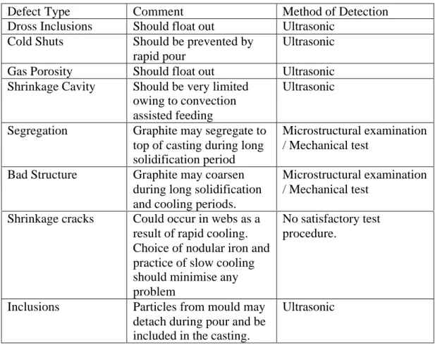
The defect types that might occur in direct castings are summarised in table 1 below together with comments and methods of detection.
Table 1 Defects that might arise in direct castings for the load bearing liner
Defect Type Comment Method of Detection Dross Inclusions Should float out Ultrasonic
Cold Shuts Should be prevented by rapid pour
Ultrasonic
Gas Porosity Should float out Ultrasonic Shrinkage Cavity Should be very limited
owing to convection assisted feeding
Ultrasonic
Segregation Graphite may segregate to top of casting during long solidification period
Microstructural examination / Mechanical test
Bad Structure Graphite may coarsen during long solidification and cooling periods.
Microstructural examination / Mechanical test
Shrinkage cracks Could occur in webs as a result of rapid cooling. Choice of nodular iron and practice of slow cooling should minimise any problem
No satisfactory test procedure.
Inclusions Particles from mould may detach during pour and be included in the casting.
Ultrasonic
It is emphasised:
1. That the comments in Table 1 apply only to the casting procedure practised by Valmet and described above. Variations in casting procedure such as reduction in pouring speed, variation in casting temperature, change in the method of bonding the sand or change to indirect casting could lead to the increased probability of damaging defects arising. Control of the process is therefore very important. And
2. That whilst Die penetrant and Ultrasonic test procedures are satisfactory in principle for detection of defects as shown, it is necessary in the case of ultrasonic to calibrate the procedures to the particular test cases.
2.1.2. Indirect casting
Indirect or uphill casting is frequently preferred over direct or downhill casting in order, among other things, to limit the entrapment of slag and dross in the casting and
splashing on the mould wall which leads to mould erosion and to avoid surface turbulence which leads to entrapment of oxide.
It is characterised however by slower filling and by an increased difficulty of feeding because the coldest material is at the top of the casting as it fills. This difficulty is usually overcome by the use of feeders into the heavier sections of the castings.
Experience in early trials conducted for SKB indicated that, for the conditions used in the trials, feeding was a significant problem and that the castings produced were seriously unsound. Large and cumbersome feeders used on the heavy sections of the castings failed to overcome this problem6. The advice of foundrymen experienced in production of such large iron castings was to change to direct casting. Experience to date indicates that the advice was sound in practice. In retrospect, the justification for using of direct casting was supported by others, as indicated in the earlier section.
It now seems unlikely that indirect casting will be considered further. Whilst, in general indirect casting may be preferred to direct casting, it is not preferred for this particular case. The reason is connected to the unusual size of the casting as indicated in the previous section.
The same group of defects may arise in direct and indirect castings but their relative importance varies from one approach to the other. Thus in the following table, the list of defects and methods of detection are the same as for direct casting. The comments are different in some cases.
Table 2 Defects that might arise in indirect castings for the load bearing liner Defect Type Comment Method of Detection
Dross Inclusions Should be limited by control of the molten metal
Die penetrant / Ultrasonic
Cold Shuts May be produced by local solidification at the mould wall during filling.
Ultrasonic
Gas Porosity Should be limited by control of molten metal.
Ultrasonic
Shrinkage Cavity Difficult to avoid owing to low rate of fill.
Ultrasonic
Segregation Graphite may segregate to top of casting during solidification period.
Microstructural examination / Mechanical test
Bad Structure Graphite may coarsen during solidification and cooling periods.
Microstructural examination / Mechanical test
Shrinkage cracks Could occur in webs as a result of rapid cooling. Choice of nodular iron and practice of slow cooling should minimise any problem
No satisfactory test procedure.
Inclusions Particles from mould may detach during pour and be included in the casting.
It should be recognised:
1. That segregation and coarsening of graphite may be affected more by the degree of superheat of the melt than by the casting method, however at constant superheat the slower rate of fill in indirect casting will reduce these effects. And
2. Reducing superheat will have a more seriously adverse effect with respect to shrinkage defects for the indirect than for the direct case.
2.2. Continuous castings of OF grade copper ingots
The ingots for extrusion or pierce and draw processing are specified as OF Copper with 50 ppm Phosphorus added and also with other elements limited to the values given in ppm below6.
Ag As Fe S Sb Se Te Pb Bi
25 5 10 <8 4 3 2 5 1
Cd Mn Hg Ni Sn Zn H P O
1 0.5 1 10 2 1 <6 40-60 5
So far suitable ingots have only been made by Outokompu at their Pori works and the specification has been designated as OFEP-OK. This grade is made from cathode which is more pure than the OF specification demands. It is produced in the casting line for Outokompu´s grade OF (E) which typically has impurity levels (excluding silver) of less than 30 ppm. Melting7 is in a 40-ton induction furnace having a melting capacity of 10 tons per hour. After the melting furnace is a 30 ton holding furnace which feeds the continuous caster through a launder.
It is very important to keep the material in the melting and holding furnaces
uncontaminated with alloying elements or impurities since in continuous processing, residues of such alloying elements or impurities would require to be flushed through the melting and holding furnaces between the production of separate alloys. This would be a very long and costly process. Thus the only alloys which can be made routinely on the OF (E) line are the silver bearing alloys. The reason for allowing silver alloys to be made on the line is that the total impurity level in OF (E) material is given net of silver. This is because silver is recognised as having no adverse effect on OF (E) material. To date one cast made for canister production has had a higher than expected silver content7. This is because a silver bearing alloy had been made on the line immediately before the cast for SKB and residual silver was still contaminating following casts. There is no evidence to suggest that such contamination by silver would have a negative effect on the material to be used for canisters. The considerable evidence, which does exist, indicates the effects of silver at residual levels (i.e. below the levels (<0.08%) which are deliberately added to raise the softening temperature of lightly rolled material for applications requiring high electrical conductivity8) would be neutral.
A consequence of using this type of manufacturing route is that additions of phosphorus must be made as phosphorus bearing master alloy in the launder, immediately prior to casting. This allows very poor control over phosphorus level, both within a single casting and between castings.
The reasons for adding phosphorus which have been given by SKB is to increase recrystallization temperature and improve creep strength and the reason given for limiting it to 50 ppm is to avoid adverse effects of phosphorus during electron beam welding. The manufacturing trials to date have resulted in analysis values lying between 40 ppm and 85 ppm. There is no published information at present on any likely effects of this variation in phosphorus content. It is a function of the process and it may be very difficult to control. Detailed information on the critical level of phosphorus for electron beam welding is not currently available. It is not clear whether or not problems
experienced in welding to date are related to this variability.
Owing to the very large size of the ingots required for pierce and draw or extrusion processing (1m diameter and 2.6 m long), it is not possible to use fully continuous casting. Semi-continuous casting is used and a single ingot is cast in each run. The casting rate of 4-5 cm per minute, which is unusually slow, is limited by the rate of melting in the furnace and the rate of cooling in the mould. Since it would be very difficult to increase the rate of cooling in the mould and to produce more than one ingot in a single run there is little point in increasing melting rate.
Normally material of this composition, made by continuous casting, is susceptible both to centre line (star) cracks and to surface breaking cracks. These kind of cracks arise as a result of shrinkage during solidification (the sharp melting point reduces the
opportunity for feeding which is available for an alloy with an extended freezing range). No surface cracks have been observed to date and the centre line cracks, which have been seen, are said by Outokompu to be restricted to the top end of the ingot rather right through it. Outokumpu suggest that these centre line cracks are the remnants of primary pipe after the top of the cast ingot has been removed and that the reason for the absence of this defect through the length of the ingot is a result of the very slow cooling rate.
Outokompu accepts however that star cracks and surface breaking cracks are a possibility in continuous production. They also expect to see some segregation of phosphorus to the centre of the ingot. Normally centre line cracks may be observed (if they are present) with the unaided eye in a machined cross section of the as cast ingot. They are usually free of oxide in truly continuous casting and they are of no
consequence provided that they are closed and welded in the early stages of
metalworking. In this case however they are not free of oxide as they may be large and they are exposed to an oxidising environment during the cooling of the ingot. Hot working may disrupt and disperse the oxide and weld the surrounding material to provide a nominally sound product but this depends on the detail of the hot working process.
It is understood that SKB intend to model both the extrusion and pierce and draw processes to determine where and how, oxide originating in shrinkage cracks is distributed in the final product. It will then be necessary to decide whether or not the oxide particles are damaging. This will depend on their size and location. Large oxide particles or clouds of small oxide particles would cause difficulties during electron beam welding, depending on their proximity to the surface and their size; they may influence corrosion or load bearing behaviour. Detection of such oxide particles is not easy. There is an expectation at SKB that they may be revealed by ultrasonic inspection.
This will depend on their size, their proximity to the surface and the microstructure in the copper. The further they are below the surface the less will be their damaging effect.
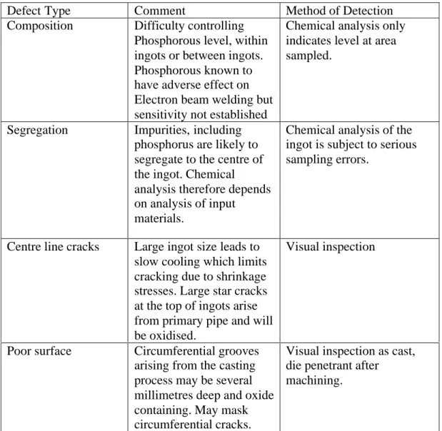
Table 3 Defects that might arise in Continuously cast ingots for tubular production
Defect Type Comment Method of Detection Composition Difficulty controlling
Phosphorous level, within ingots or between ingots. Phosphorous known to have adverse effect on Electron beam welding but sensitivity not established
Chemical analysis only indicates level at area sampled.
Segregation Impurities, including phosphorus are likely to segregate to the centre of the ingot. Chemical analysis therefore depends on analysis of input materials.
Chemical analysis of the ingot is subject to serious sampling errors.
Centre line cracks Large ingot size leads to slow cooling which limits cracking due to shrinkage stresses. Large star cracks at the top of ingots arise from primary pipe and will be oxidised.
Visual inspection
Poor surface Circumferential grooves arising from the casting process may be several millimetres deep and oxide containing. May mask circumferential cracks.
Visual inspection as cast, die penetrant after
machining.
Surface breaking cracks may be very difficult to detect on an as cast surface owing to the very poor surface quality. The surface quality is poor owing to circumferential grooves that arise in the casting process. They may be some millimetres deep and they are claimed by Outokompu to be round bottomed. No evidence for this has so far been provided however.
The surface grooves, as well as any shrinkage cracks will be oxidised. The oxide will eventually arise in the finished product unless measures are adopted to prevent it. When further processing is by extrusion the surface is improved by machining to remove all the circumferential grooves. This machining may also remove any surface cracks that are present. If it does not then die penetrant testing would reveal them. If they are shallow they may be removed by dressing the surface and if they were judged to be too deep they would lead to rejection of the ingot.
Pierce and draw processing is applied to the as-cast ingot and this means that some surface defects may be incorporated in the finished product. It seems inevitable
therefore that oxide particles will be included in the structure of the tubular. As with the extrusion case their effects will depend on their location and their size.
There is no indication at this point as to the level of homogenisation that occurs during processing and it is not clear therefore whether the segregation of phosphorus to the ingot centre described by Outokompu will be redistributed during further processing. This should be clarified as the development progresses.
The macrostructure of the as cast ingot is typical of a continuously cast product with relatively fine chill grains near the surface followed by columnar grains extending towards the centre and apparently equiaxed grains in the centre of a transverse section. The untypical feature is the size of the as cast grains which is unusually large. This is worthy of mention because the further processing of the ingots may be less than would be usually applied to an as cast structure (pierce and draw for instance). At present there is no information on the homogeneity of the structure in the extruded or pierced and drawn structures. The modelling procedures which are to be undertaken may shed some light on the level of deformation which is likely to occur but eventually it may be necessary to examine the uniformity of the structure achieved and the homogeneity of the composition by destructive testing.
Details of ingot defects are summarised in table 3 above.
2.3 Copper tubes made by extrusion
Copper tubes are extruded from ingots described in 2.2 above. The surface is machined to produce a diameter of 840 mm and the length is adjusted according to the final wall thickness that is targeted. The extrusion process and defects that might arise have been discussed with technical staff at Wymann-Gordon9 in Livingstone UK.
Significant defects that may be in the ingot at the outset are centre line cracks and surface cracks or inclusions arising in the casting process. Centre line cracks may be large and they may extend along the length of the ingot. They are likely to be visible to the unaided eye. Surface cracks may be closed and difficult to see. They may however be detectable using the die penetrant method. Both these defects could be oxidised and the oxide could be dispersed in the final extruded tube. It is a commonly held view that oxide from this origin would appear as dispersed particles in the inner or outer surface layers of the extruded product. Such distributed particles could be removed by the final machining or they could remain in the machined product if the original defects are extensive. If dispersed oxides are present in the finished tubular and the grain size of the material is controlled to the less than 100 µm value, which is currently being achieved, then the oxides should be detectable by ultrasonic inspection.
Inclusions arising from casting would be broken up and distributed through the tubular as fine particles. Strings of such particles may or may not be near the surface depending on the original position of the inclusion in the ingot. They would be detectable by ultrasonic inspection. Their effect on the integrity of the canister is not established but they could have negative effects on corrosion resistance or strength properties.
The first stage of processing is to produce a “blocker” by forging to reduce the height of the ingot and increase its diameter. The diameter is increased from 840 mm to 1450 mm, which corresponds to a three-fold reduction in height. This forging operation is conducted in an open container that controls the finished dimensions. The bottom corner of the container is radiused. The purpose of the radius is to assist the entry of the
blocker into the extrusion die but it also has the effect of reducing the tendency to form forging laps as the final expansion of the ingot occurs to fill the blocker chamber.
Forging laps are defects that arise when the surface material is folded over during the forging operation15. The surface material is oxidised and the process of folding creates a film of oxide extending from the surface to the interior of the blocker. This film would be broken up and dispersed during extrusion. It would occur as a “cloud” of oxide particles in the extruded product. Their effect would depend on their location and their size. As with the other defects that have been referred to, they would be detected by ultrasonic inspection.
After forging to fill the chamber the blocker is pierced to accept the extrusion mandrel, this causes some back extrusion in the blocker chamber. Finally the die descends over the blocker and mandrel forcing the copper to extrude vertically through the die. For tubes with a final wall thickness of 30 mm the target wall thickness of the extrudate is 46 mm. The overall extrusion ratio for this case (from the entire blocker to the tube) is 6. This coupled with the original upsetting process should be sufficient to break up the ingot structure and provide a uniform grain size providing that the temperature is
controlled to prevent the onset of grain growth. Trials to date have demonstrated that an extrusion temperature of 675 ºC achieves this for the extrusion with a 70-mm wall thickness. It remains to be demonstrated for the lesser wall thickness and it is possible that an alternative extrusion temperature may be required.
Defects that could occur during extrusion are hot tearing, speed cracking, and bad shape. Hot tearing arises as a result of friction between the die and the workpiece and is manifest as jagged circumferential surface cracks. They would normally be visible to the unaided eye. If they escape visual detection there may be residual surface breaking cracks after machining. These cracks would be detectable by die penetrant testing. Speed cracking is a defect that arises in extrusion when the heat generated by the extrusion process is sufficient to cause localised melting in the extrudate. It is
recognised by circumferential cracks on the extruded product and it is now believed that this is the defect, which has been previously reported but not explained by the present writer6,12. It is prevented by controlling the extrusion temperature and the extrusion speed. Bad shape would result in difficulty in achieving the target dimensions after machining.
Details of defects that might arise in extruded tubulars are summarised in table 4 overleaf.
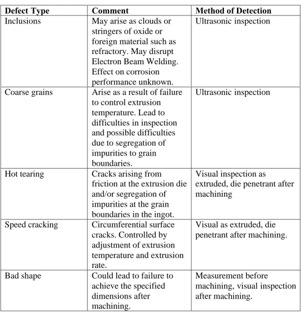
Table 4 Defects that might arise in extruded tubulars
Defect Type Comment Method of Detection
Inclusions May arise as clouds or stringers of oxide or foreign material such as refractory. May disrupt Electron Beam Welding. Effect on corrosion performance unknown.
Ultrasonic inspection
Coarse grains Arise as a result of failure to control extrusion temperature. Lead to difficulties in inspection and possible difficulties due to segregation of impurities to grain boundaries.
Ultrasonic inspection
Hot tearing Cracks arising from
friction at the extrusion die and/or segregation of impurities at the grain boundaries in the ingot.
Visual inspection as
extruded, die penetrant after machining
Speed cracking Circumferential surface cracks. Controlled by adjustment of extrusion temperature and extrusion rate.
Visual as extruded, die penetrant after machining.
Bad shape Could lead to failure to achieve the specified dimensions after machining.
Measurement before
machining, visual inspection after machining.
2.4. Copper tubes made by the pierce and draw process
The pierce and draw process is practised by Vallourec & Mannesmann at their
Dusseldorf works. Details of the process have been obtained by visiting the works and discussing the process with technical staff10.
Ingots are taken, as cast, from the supplier and processed with no preliminary treatment. Preheating for all stages of processing is in a pit furnace under an oxidising atmosphere. Any star cracks in the ingot will therefore be further oxidised in the first reheat.
The reheated ingot is upset in a closed chamber to reduce the ingot length and increase its diameter to fit the piercing chamber. Piercing using a solid mandrel follows
upsetting. This sometimes leads to the formation of circumferential cracks as a result of friction at the die or segregation of impurities in the ingot. The inner and outer surfaces are machined after piercing to remove these cracks. Crack detection after machining is by die penetrant testing. If the cracking arises from segregation of impurities to grain
boundaries (hot shortness) then it can recur on subsequent draws. Although much is made of the very high purity of OF (E) copper in the context of resistance to hot shortness, it should be realised that to a first approximation 3 ppm of impurities are required to provide a complete monolayer of impurities in grain boundaries when the grain size is 400 µm. Similarly 1 ppm would be capable of providing a monolayer when the grain size is 1200µm. Grain sizes in this range will certainly be present during hot working. The actual impurity levels excluding Silver and Phosphorus will be close to 30 ppm and the impurities that are segregated will not form a uniform layer. The possibility of hot shortness therefore cannot be discounted, indeed hot tearing, which depends on a similar mechanism has been observed close to repairs in electron beam welds.
Following piercing and machining, the workpiece is subjected drawing through a succession of dies to reach final dimensions. Reheating is conducted in the pit furnace between draws as required. As an alternative to drawing (which reduces the diameter and wall thickness) it is possible to expand the diameter whilst also reducing the wall thickness. The disadvantages of expanding the diameter whilst reducing the wall thickness are:
1. Any variation in wall thickness that arises in drawing is accentuated in later draws unless it is removed by machining between draws. And
2. Expansion steps can lead to cracking at the boundaries of coarse grains (hot shortness).
One tubular has been made by the pierce and draw process to date and examination has revealed that there is a gradient in grain size from fine at the top to very coarse at the bottom. In this context fine is understood to mean 300 µm and coarse is 1 mm plus. The reason for the gradient in grain size is a gradient in cooling rate that is inherent in the process, even the finer grains reported for this case are very coarse however.
For this first attempt, the final step was carried out at 750 °C, which is too high. The temperatures of the earlier steps have not been disclosed but it has been disclosed that they were higher than 750 °C. The final grain size is therefore not surprising.
The upsetting reduced the length of the ingot by 39% and increased the diameter from 860 to1050 mm. Piercing was with a mandrel of 745 mm diameter. Following
machining of the surfaces, the further processing used dies to increase the diameter and reduce the wall thickness to the dimensions given above. Five steps were employed with reheating between each step.
Mannesmann would prefer to use drawing down rather than expansion steps but this would require a greater diameter upsetting and piercing chamber and none is available. They would also prefer to have a larger ingot because it is difficult to achieve the required yield for a full size tubular from the existing ingot size.
The multiple steps are a weakness in the process since the individual steps provide limited amounts of hot work and reheating is carried out in a pit furnace under oxidising conditions. The limitation on hot work limits the refinement of the structure and any cracks opened up in an individual step will be oxidised in the furnace and lead to oxide inclusion-defects being formed in later steps. For smaller components machining between steps may be practised but in this case the initial ingot size will not allow it.
Centre line cracks in the original ingot are driven ahead of the piercing mandrel to the base of the drawn tubular and it has been suggested that the oxidised material associated with the cracks then remains in the bottom that is subsequently removed. As the steps after piercing are tensile rather than compressive along the axis of the tubular, it is likely that material in the bottom remains there. However if the cracking in the ingot is
extensive it is likely that some of it may be displaced into the wall of the tubular during piercing. If this happens then it is likely that stringers of oxide inclusions will arise in the finished product.
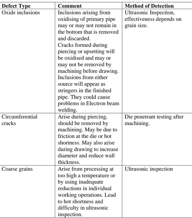
Details of defects, which may arise in tubulars made by the pierce and draw process, are summarised in table 5 below.
Table 5 Defects that might arise in tubulars made by the pierce and draw process Defect Type Comment Method of Detection
Oxide inclusions Inclusions arising from oxidising of primary pipe may or may not remain in the bottom that is removed and discarded.
Cracks formed during piercing or upsetting will be oxidised and may or may not be removed by machining before drawing. Inclusions from either source will appear as stringers in the finished pipe. They could cause problems in Electron beam welding. Ultrasonic Inspection, effectiveness depends on grain size. Circumferential cracks
Arise during piercing, should be removed by machining. May be due to friction at the die or hot shortness. May also arise during drawing to increase diameter and reduce wall thickness.
Die penetrant testing after machining.
Coarse grains Arise from processing at too high a temperature or by using inadequate reductions in individual working operations. Lead to hot shortness and difficulty in ultrasonic inspection.
2.5. Copper plates suitable for fabricated tubes of the
relevant dimensions.
The fabrication of tubulars requires heavy plate. The individual plates need to be 60 to 70 mm thick depending on the machining allowance and they need to be 1.5 m wide and 5 m long. Ideally they should have a fine equiaxed grain structure and fine grained usually means a mean grain diameter of less than 100 µm. Such a grain size is normal in the copper industry and many specifications are based on the assumptions that they will be achieved.
Such a grain size is routinely achieved when section sizes are small and when cold rolling and annealing is employed. They are much more difficult to achieve in heavy sections.
Conventional wisdom is that in order to achieve a satisfactory structure a rolling reduction of 90 percent is desirable. For 60-70 mm thick plate this requires an ingot of 600 to 700 mm starting thickness. A range of ingot width to length ratios could be calculated which in principal would allow a single or possibly two plates to be produced from one ingot and a suitable ingot could be produced by direct casting. Finding a mill that would open up to 700-mm daylight with large enough rolls to draw the ingot in for the first pass would be difficult if not impossible.
A compromise solution to this problem is to aim for a very good structure in thinner continuously cast slab and use controlled rolling to achieve the best possible result. This has tried in the by three different rollers in the SKB programme. It is believed that typical slab thicknesses were 270 mm.
SKB have obtained heavy plates, from Revere Copper in the USA, MKM in Germany and from Birmingham Rolled Metals (BRM) in England11. None of these plates were fine grained. In the best cases SKB claimed a mean grain size of 350µm. Very mixed grain sizes were reported in some cases. The significance of this is that if finer more uniform grain sizes cannot be achieved it will be necessary to establish non-destructive test procedures that are reliable for coarse-grained material. It will also be necessary to reconsider the levels of residual elements that will be acceptable in the plates, since certain of them, such as sulphur will be accommodated in a much lower grain boundary area than was present in specimens used for corrosion and creep tests.
Other defects that may appear on rolled plates are surface cracking due to hot shortness, poor surface due to oxide being rolled in and laminations on edges. Cracking would be detected visually by die penetrant methods. Laminations would be detected
ultrasonically and rolled in oxide would be visually observed. Lamination defects should be removed with the edge trim and surface defects by the final machining operations.
Details of defects that might arise in heavy plates prepared for fabrication of tubulars are summarised in table 6 below.
Table 6 Defects that might arise in heavy plates prepared for fabrication of tubulars
Defect Type Comment Method of Detection
Coarse grains Unavoidable in plates of this size. Present extra difficulties in ultrasonic inspection and increase problems arising from grain boundary segregation
Ultrasonic/microscopical examination.
Surface cracking Arising from hot shortness coupled with problem of coarse grains. May or may not be removed by final machining
Visual examination/Die penetrant testing
Laminations From rolling over of edges, should be removed by trimming
Visual/Ultrasonic testing
Bad surface From rolling of oxide or debris, may be removed by final machining
Visual examination
2.6. Roll formed semi-cylinders in copper.
Plates supplied by Revere Copper and by MKM have been used in roll forming trials at Vickers Shipbuilding and Engineering Limited (VSEL) in England and at Kockums in Sweden.
The plates were 60 mm to 70 mm thick, 1.75 m wide and 5 m long. The roll forming machines at both companies are similar12. They are up to 18 m long; they have two lower rolls and one top roll. All rolls are supported along their length by jockey rolls to prevent bending. The gap between the lower rolls can be varied and the height of the top roll can be adjusted. This enables a gradual change in radius during reversing rolling operations. Such a machine needs a material allowance of three times the material thickness along each edge, which will be undeformed and needs to be removed after roll forming. The radiusing of the work is achieved by reversed rolling whilst the gap
between the top and bottom rolls is continuously adjusted. It is a manually controlled craft operation that depends on the skill of the operator. Difficulty is experienced in maintaining a constant radius of curvature along the entire length of the work and in keeping the rolled section straight.
The edge trims are taken by plasma cutting and the cut edges are machined ready for fitting together (fit-up) before welding. None of the semi-cylinders produced have been either straight or round but measurements indicated that discrepancies would be within the machining allowance after welding. All prepared semi-cylinders have been supplied to TWI for welding.
Defects present in the rolled plates will persist in the roll formed plate. In addition residual stress are produced, which may lead to critical strain grain growth during the stress relieving treatment and the shape is invariably bad leading to difficulties in machining to final dimensions.
Details of defects that might arise in roll formed semi-cylinders, for tubular production, are given in table 7 below.
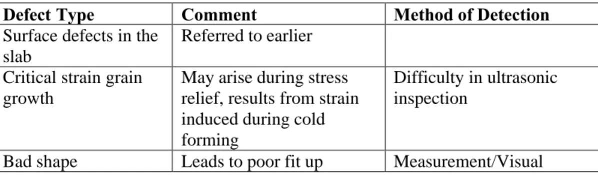
Table 7. Defects that might arise in roll formed semi-cylinders for tubular production
Defect Type Comment Method of Detection
Surface defects in the slab
Referred to earlier
Critical strain grain growth
May arise during stress relief, results from strain induced during cold forming
Difficulty in ultrasonic inspection
Bad shape Leads to poor fit up Measurement/Visual
2.7. Welded Tubulars
Electron beam welds used for joining semi-cylinders are made using the standard high-vacuum electron-beam welding process with the beam vertical. This process has been described elsewhere12. Defects in the welds per-se are dealt with in section 2.8. The work is set up for welding in a restraining jig with the axis of the tube horizontal and the electron beam vertical. The residual stresses after roll forming together with the welding stresses lead to a need for a very strong restraining fixture to prevent
deformation during welding. The consequence of this is that very severe internal stresses are developed and the tubular deforms after the restraining fixture is removed.
In order to prevent further deformation during final machining it is necessary to stress relieve the tubular before machining. Since the deformation imposed during roll forming varies between zero and ten percent the possibility of critical strain grain growth during stress relieving arises. Finally distortion during stress relieving may result in the machining allowance becoming too small to enable a tubular of the correct dimensions being produced.
Hot tearing has been observed12 in the vicinity of seam welds used for joining of semi-cylinders to form tubulars. This is a form of hot shortness that arises when grain boundaries open up under the influence of the welding stresses in the heat affected region of the workpiece.
Details of defects that might arise in welding of roll formed semi-cylinders to produce tubulars are given in table 8 below.
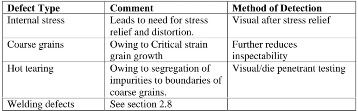
Table 8 Defects that might arise in welding of roll formed semi-cylinders to produce tubulars.
Defect Type Comment Method of Detection
Internal stress Leads to need for stress relief and distortion.
Visual after stress relief
Coarse grains Owing to Critical strain grain growth
Further reduces inspectability Hot tearing Owing to segregation of
impurities to boundaries of coarse grains.
Visual/die penetrant testing
Welding defects See section 2.8
2.8. Electron beam welds
2.8.1. Linear Defects
There are three common linear or crack like defects13, which have been observed in the development programme for the canister. The first is a missed weld line and the second is weld-root defect and the third is incomplete penetration.
The missed weld line may be full thickness (a complete miss) or partial thickness. The complete miss may arise through bad set-up, through deflection of the beam or through movement of the work arising from thermal expansion effects. The partial miss is more commonly seen. It arises in horizontal welding when the beam tilts upwards in the work. This tilt always happens when deep horizontal electron-beam welds are made although its cause is unknown. It may result in the surface being missed whilst the root is welded if initial misalignment is present but more commonly, when alignment at the surface is correct, it occurs at the root only.
Weld root defect occurs in thick welds either in the main full thickness weld or in the tapered run out region at the end of the weld. It can cause a string of crack like defects (cold shuts) which, individually, may be up to 5 mm long. The string may extend from the surface to the full weld depth. It is said to arise from poor wetting of the tip of the weld cavity by the molten metal.
The third linear defect, incomplete penetration leads to a crack like defect at the root of the weld. It is caused by lack of good control of the beam power or the beam power to rotational speed ratio, poor beam focus, the chamber pressure being too high or running out too soon.
All three of these defects should be detectable using ultrasonic inspection but coarse grains in the weld or the parent material or compressive stresses across the weld line may make it difficult. There is at present no solution to coarse grains in the weld but it seems likely that extrusion and forging will prevent them in the parent materials. The effect of compressive stresses on detectability of the crack like defects may be reduced, by using a rough surface on the parts to be welded.
A low pressure rather than a high vacuum electron beam welding process has been developed for attaching lids and bases with the specific aim of reducing the frequency of occurrence of these defects. It provides a very wide weld line, which makes the intended weld line more difficult to miss, and a weld–pool that is tear-drop shaped with the rounded end at the bottom. This shape of weld pool should ensure wetting of the tip of the weld cavity and its increased volume provides more molten metal to feed cavities, which would form by shrinkage during the very rapid cool. The beam may also be tilted downwards to counteract the natural upward tilt.
The disadvantages of the process are that it requires very high power (to melt the increased volume of metal) and, there is an increased tendency for leakage between the welding chamber and the electron gun (arising from the pressure differential). The latter problem may be compounded by an increase in the release of gaseous species from the weld-pool following zone refining. These disadvantages conspire to increase the frequency of flash-over in the electron gun which may interrupt welding and cause defects which so far have been impossible to repair (these will be referred to later).
Improvements have been made in the design of the electron gun and the control systems in order to overcome these problems.
Table 9 Linear Weld Defects
Defect Comment Cause Detection
Method Prevention
Missed joints May be complete
Or partial Bad set up Beam deflection Movement through expansion Beam tilt U/T-unless residual stresses are compressive across the joint-alleviate by rough surface on the joint Good housekeeping Tilt beam downwards Weld root defect A series of cavities may link surface to full weld depth
Poor wetting of weld cavity tip
As above Use reduced pressure process
Lack of penetration
Weld short of full depth
Beam power to speed ratio wrong,
Beam power too low,
Chamber pressure too high
Beam focus poor Running out too soon
As above Good process control
2.8.2. Cavities
During the development programme gas porosity and cavities in welds arising from poor feeding (shrinkage) have both been observed.
Gas porosity is usually in the form of small pores, up to 0.5mm diameter but they may on occasions be very large, that is up to the full weld width. Small pores, which arise from impurities (principally oxygen as Cu2O) in the parent material, may be located at
the fusion boundaries or near the surface of the weld. Larger pores may arise from contamination of the surfaces by cleaning materials or by oxide particles or oxidation of the surfaces between cleaning and welding.
Cavities are generally larger than gas pores. They are typically 3-4mm in diameter and they might extend for long distances at the root of the weld or in the run out region. The basic cause is poor feeding during solidification. This may arise from pore focus of the electron beam leading to dissipation of energy in too large a volume of material, beam instability, poor fit-up or loss of metal through run out.
Pores are difficult to prevent and cavities are only controlled by maintenance of robust procedures in processing. Of course the robust procedures need to be devised and proved.
Detection is by ultrasonic testing or radiography or near the surface through eddy current testing. Small pores are hard to detect and cavities are difficult to size because of their irregular shape.
Information on cavity defects is summarised in Table 10 opposite.
2.8.3. Underfilling
An integral backing plate is used for lid and base welds and the tack weld is made through it. Its purpose is to prevent run out of molten metal. It works for most of the time but when the process becomes unstable for any reason such as poor fit up, failure of the tack weld, degassing of the melt or flash over then metal may be lost from the weld pool. Usually this will lead to a surface underfill that may not be a problem since the surface is cleaned by machining after welding. If the beam supply is interrupted as when flash over occurs, however, then a deep underfilling defect may be created. Such deep defects may be detected by Ultrasonic testing, subject to the difficulties mentioned earlier or by radiography.
These defects are only avoided by the use of robust and tolerant procedures coupled with good process control.
Table 10 Cavity defects
Defect Comment Cause Detection
Method Prevention
Gas porosity May be at fusion boundary or may float to top of weld before being trapped. 0.5 mm diameter to full weld width Impurities in the parent metal, Inadequate cleaning. Radiography or U/T Low frequency eddy current for near surface. May be difficult to detect when small or when grains are coarse Good surface cleaning, weld soon after surface cleaning. Shrinkage cavities Especially prevalent at run out. Could be 3-4 mm in diameter and very long
Poor feeding, loss of metal, beam instability As above Difficult to size owing to irregular shape Use a robust procedure with tolerance to likely variations in material or process variables.
Table 11 Underfilling defects
Defect Comment Cause Detection
Method Prevention
Surface underfill
Metal loss by run out, through poor fit up, inadequate tack welding, lacks of control / gun discharge. Visual Robust procedures and process control Root underfill
As above U/T As above
2.8.4. Cracking
Cracking is rare in association with welds in OF copper owing to its high purity and very high ductility. Nevertheless hot tearing does occur and particularly in association with coarse grains. Tears have been seen in welds on the centre line and parallel to the welding direction and also in positions close to the weld, which are affected by the welding process.
In the welds they have been attributed to the enhanced segregation of impurities during repair operations coupled with shrinkage stresses. I areas adjacent to the weld they are
believed to be a result of hot shortness brought about by the segregation of impurities to the boundaries of very coarse grains coupled with the heating from welding operations and the welding stresses. Away from the welds these defects may be avoided by avoiding coarse grains. Within the welds they may be avoided by avoiding repair procedures.
Detection is by visual or die penetrant inspection close to the welds or by Ultrasonic testing in the welds.
Information relating to crack defects is summarised in table 12 below.
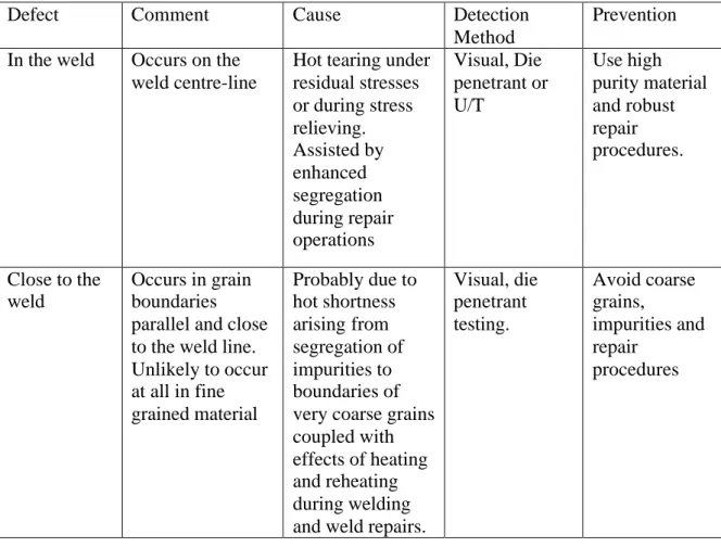
Table 12 Cracking
Defect Comment Cause Detection Method
Prevention
In the weld Occurs on the weld centre-line
Hot tearing under residual stresses or during stress relieving. Assisted by enhanced segregation during repair operations Visual, Die penetrant or U/T Use high purity material and robust repair procedures. Close to the weld Occurs in grain boundaries parallel and close to the weld line. Unlikely to occur at all in fine grained material Probably due to hot shortness arising from segregation of impurities to boundaries of very coarse grains coupled with effects of heating and reheating during welding and weld repairs.
Visual, die penetrant testing. Avoid coarse grains, impurities and repair procedures
2.8.5. Gun Discharge Defects
Gun discharge defects arise as a result of flash over. When repeated flashover occurs, the welder is automatically stopped in the interest of safety. If welding is stopped it is necessary to restart by running in to full depth over a distance in the already welded material, this can lead to weld root defect in the run-in distance. Discharges, that do not cause a stop in welding, are detected by the welding equipment and the position where they occur is recorded. A crack like defect that arises from shrinkage and can extend for the full depth of the weld may arise from flash over events. Repair of defects by re-welding requires both a run in and a run out on either side of the repair. The run in and run out need to be inspected for weld root defect. Discharges may arise, as a result of outgassing in the workpiece but it is believed that the latest gun design will greatly
reduce the incidence of flash over. It is claimed that flash over is more a function of gun design than of the quality of the copper and that the flash over is less frequent in
reduced pressure welding than in high vacuum welding. However it has been observed that in reduced pressure welding the frequency of flashover is reduced by reducing the delay between cleaning or tack welding and final welding. This suggests that
contamination of the copper has a negative effect.
Information relating to gun discharge defects is summarised in table 13 below.
Table 13 Gun discharge defects
Defect Comment Cause Detection
Method Prevention
Shrinkage cracks
May extend for the full depth of the weld
Arise from discharges, which are initiated by the back flow of ions into the high vacuum region of the gun. Ultrasonic inspection of discharge position Good gun design and maintenance, Minimum delay between cleaning and tack welding, Minimum delay between tack welding and final welding. Low gas content, including Cu2O in the copper. Low levels of atomic species which will volatilise over the weld pool. Weld root
defect
In repaired areas Arises in run in and run out
Ultrasonic inspection
Good control of the welding.
2.9. Copper forgings for lids and bases.
The starting stock for lids and bases is 350-mm diameter continuously cast ingot to specification OFEP-OK given in section 2.2 above. The ingot length is 1.4 metres and it is upset to a flat disc in three stages with a starting temperature of 800° C and reheating to the same temperature between stages.
Ingot to this specification is likely to have centre line (star) cracks, which may extend along the entire length. Surface cracks (longitudinal) are also possible. However any problem in the casting process, which would be likely to cause surface defects, would be so unusual that defective material would be readily identified and rejected.
Centre line cracks would normally present no problem as they would be oxide free and they would be healed during the first stage of forging, which would be along the diameter of the ingot. In this case however there is no forging along the diameter in the early stages.
Surface cracks or other surface defects in the ingot would normally be detected before forging and the ingot would either be repaired (by dressing out the cracked material) or rejected. Surface cracks in the ingot would be oxidised and if they went undetected before forging. It is likely that they would then lead to clouds or films of oxide inclusion in the final forging. These may or may not be removed during final machining.
Forging along the length of the ingot (upsetting) may in some cases lead to opening up of the centre line cracks and oxidation of the crack surfaces. Subsequent reheating and forging steps may increase the total amount of oxidation and disperse the oxide within the structure of the forging. Such oxide inclusions could form unacceptable lines of weakness in the forging or cause difficulties in electron beam welding. In addition to opening of centre line cracks the upsetting operation can cause longitudinal surface cracks to arise, particularly when the height of the ingot is more than twice its
diameter14. Oxidation of cracks formed in this way may lead to large oxide inclusions when they are closed in subsequent forging steps.
If the cracking problem arises it would be because the forging process, which is selected to suit the dimensions of the starting material, is non ideal. An ideal process, for this material, would start with a larger diameter ingot, so that the first stage of forging could be used to heal the centre line defects. Unfortunately larger diameter ingots are not routinely made in this material and this is partly because a larger diameter accentuates the problem of centre line cracking during casting. Conventional casting could be used to produce larger diameter ingots but this approach would bring its own problems related to surface quality and relatively poor yield. There is no obvious solution other than careful process control to minimise oxidation during reheating and good
lubrication of the forging tup and anvil during upsetting to minimise surface cracking.
The forged shape is rather simple and defects arising from the metal flow such as forging laps should be rare. However the ratio of height to diameter (h/d ratio) of a forging ingot is usually controlled to 2 or less14, 15 to prevent buckling in the upsetting stage. Such buckling does lead to forging laps. The h/d ratio used in this case is 4 for the reasons given above. Forging laps arise when, during forging, an area of surface
material, which carries scale or an oxide film is folded over so as to include the oxide as a film, which may be quite thick, running from the surface to the interior of the
forging16. If they do occur, they should be revealed by visual inspection of the premachined forging or by eddy current inspection of the machined product.
The significance of oxide inclusions will depend on their size and location whether they arise as a result of ingot defects or the forging practice. No specification exists at
present but it seems likely that clouds of small oxide inclusions would not have a seriously negative effect on mechanical performance. It must be for SKB to determine the levels that are tolerable. Should such defects occur close to the electron beam weld line, it is likely that the welding would be disrupted or even stopped. Welding defects would then be the matter for concern.
Ultrasonic inspection may be used for the detection of oxide inclusions depending on their size, the structure of the copper matrix (grain size) and their distance below the surface.
The structure of the copper will depend on the forging procedures used. The reheating temperature of 800°C will cause recrystallization and may be high enough to cause grain growth, depending on the previous forging cycle (distribution of strain and finishing temperature) and the holding time at temperature. The distribution of grain sizes in the forging will be closely related to the entire forging process. It is important to produce fine grains throughout the structure to:
(1) aid the inspection process, particularly near the welds,
(2) control the mechanical properties, yield strength and creep strength in particular and,
(3) avoid undesirable concentrations of impurities in grain boundaries owing to the reduced grain boundary area, which accompanies coarse grains.
Information relating to defects that might arise in forged lids is summarised in table 14 below.
Table 14 Defects that may arise in forged lids
Defect Type Comment Method of Detection
Oxide inclusions Arising from centre line cracks in the continuously cast forging stock. Can be lines of weakness in the forging; can interrupt electron beam welding.
Ultrasonic inspection.
Forging laps Should be rare, produce oxide films extending from the surface to the interior of the forging
Visual/ die penetrant inspection after machining
Coarse grains Cause difficulties in ultrasonic inspection, reduce mechanical
properties, and may lead to undesirable concentrations of impurities in grain boundaries.
Difficulty in ultrasonic inspection.
3. References
1. Werme L, Design Premises for Canister for Spent Nuclear Fuel- SKB Technical report TR-98-2.
2. Andersson CG, Test manufacturing of copper canisters with cast inserts-Assessment Report.
3. SKB Technical Report TR-98-09.
4. Sunden A and Thinell A, Private communication- Valmet Foundry Karlstad. 5. Campbell J, Private Communication.
6. Campbell J, Castings. Butterworth Heinemann1998. ISBN 0 7506 1696 2.
7. Bowyer W H. Design Basis for the copper canister, Stage five final report. To be published as SKI report 99:xx.
8. P Makkinen, OutoKompu Pori Copper, Private Communication. 9. ASM Metals Handbook, Desk Edition Section 7.15.
10. J Bogie, Wyman-Gordon UK, Private Communication.
11. T Smitz, Vallourec & Mannesmann Tubes Dusseldorf Germany, Private communication.
12. Bowyer WH Design Basis for the copper canister, Stage two final report. SKI report 96:47.
13. Bowyer WH, Design Basis for the copper canister, Stage three final report. SKI report 97:19.
14. Punshon C, TWI UK Private communication.
15. Schey JA, Introduction to Manufacturing processes McGraw-Hill. ISBN.0-07-055274-6 P132.
16. Alexander JM &Brewer RC, Manufacturing Properties of materials Van Nostrand 1963, Library of congress catalogue card No.63-17836.
17. Sabroff AM. Boulger FW. & Hening HJ, Forging Materials and Practices, Rheinhold Book Corp.1968. Library of congress card no 68-22274.
4. Tables
Table 1. Defects that might arise in direct castings for the load bearing liner Defect Type Comment Method of Detection
Dross Inclusions Should float out Ultrasonic Cold Shuts Should be prevented by
rapid pour
Ultrasonic
Gas Porosity Should float out Ultrasonic Shrinkage Cavity Should be very limited
owing to convection assisted feeding
Ultrasonic
Segregation Graphite may segregate to top of casting during long solidification period
Microstructural examination / Mechanical test
Bad Structure Graphite may coarsen during long solidification and cooling periods.
Microstructural examination / Mechanical test
Shrinkage cracks Could occur in webs as a result of rapid cooling. Choice of nodular iron and practice of slow cooling should minimise any problem
No satisfactory test procedure.
Inclusions Particles from mould may detach during pour and be included in the casting.
Table 2. Defects that might arise in indirect castings for the load bearing liner Defect Type Comment Method of Detection
Dross Inclusions Should be limited by control of the molten metal
Die penetrant / Ultrasonic
Cold Shuts May be produced by local solidification at the mould wall during filling.
Ultrasonic
Gas Porosity Should be limited by control of molten metal.
Ultrasonic
Shrinkage Cavity Difficult to avoid owing to low rate of fill.
Ultrasonic
Segregation Graphite may segregate to top of casting during solidification period.
Microstructural examination / Mechanical test
Bad Structure Graphite may coarsen during solidification and cooling periods.
Microstructural examination / Mechanical test
Shrinkage cracks Could occur in webs as a result of rapid cooling. Choice of nodular iron and practice of slow cooling should minimise any problem
No satisfactory test procedure.
Inclusions Particles from mould may detach during pour and be included in the casting.
Table 3. Defects that might arise in Continuously cast ingots for tubular production
Defect Type Comment Method of Detection
Composition Difficulty controlling Phosphorous level, within ingots or between ingots. Phosphorous known to have adverse effect on Electron beam welding but sensitivity not established
Chemical analysis only indicates level at area sampled.
Segregation Impurities, including phosphorus are likely to segregate to the centre of the ingot. Chemical analysis therefore depends on analysis of input materials
Chemical analysis of the ingot is subject to serious sampling errors.
Centre line cracks Large ingot size leads to slow cooling which limits cracking due to shrinkage stresses. Large star cracks at the top of ingots arise from primary pipe and will be oxidised.
Visual inspection
Poor surface Circumferential grooves arising from the casting process may be several millimetres deep and oxide containing. May mask circumferential cracks.
Visual inspection as cast, die penetrant after
Table 4. Defects that might arise in extruded tubulars
Defect Type Comment Method of Detection
Inclusions May arise as clouds or stringers of oxide or foreign material such as refractory. May disrupt Electron Beam Welding. Effect on corrosion performance unknown.
Ultrasonic inspection
Coarse grains Arise as a result of failure to control extrusion temperature. Lead to difficulties in inspection and possible difficulties due to segregation of impurities to grain boundaries.
Ultrasonic inspection
Hot tearing Cracks arising from
friction at the extrusion die and/or segregation of impurities at the grain boundaries in the ingot.
Visual inspection as
extruded, die penetrant after machining.
Speed cracking Circumferential surface cracks. Controlled by adjustment of extrusion temperature and extrusion rate.
Visual as extruded, die penetrant after machining.
Bad shape Could lead to failure to achieve specified dimensions after machining.
Measurement before
machining, visual inspection after machining.