Thermal Conductivity of
Hygroscopic Foams Based on
Cellulose Nanomaterials
Varvara Apostolopoulou-Kalkavoura
Varvara Apostolopoulou-Kalkavoura T hermal Conducti vity of Hygr oscopic Foams Based on Cel
lulose Nanoma
terials
Department of Materials and
Environmental Chemistry
ISBN 978-91-7911-406-0Varvara Apostolopoulou-Kalkavoura
was born in Athens, Greece. She holds a Diploma in Chemical Engineering from N.T.U.A. and a M.Sc. in Sustainable Technology from K.T.H. She started her PhD studies at Stockholm University in 2015.
Thermal Conductivity of Hygroscopic Foams
Based on Cellulose Nanomaterials
Varvara Apostolopoulou-Kalkavoura
Academic dissertation for the Degree of Doctor of Philosophy in Materials Chemistry at Stockholm University to be publicly defended on Friday 26 March 2021 at 13.00 digitally via Zoom, public link will be made available at https://www.mmk.su.se/
Abstract
Biobased super-insulating materials could mitigate climate change by minimizing the use of petroleum-based materials, creating artificial carbon sinks and minimizing the energy needed to maintain pleasant interior conditions. Cellulose nanomaterials (CNM) produced from abundantly available cellulose sources constitute versatile, highly anisotropic raw materials with tunable surface chemistry and high strength. This thesis includes the evaluation of the thermal conductivity of isotropic and anisotropic CNM-based foams and aerogels and analysis of the dominant heat transfer mechanisms.
We have developed a customized measurement cell for hygroscopic materials in which the humidity and temperature are carefully controlled while the thermal conductivity is measured. Anisotropic cellulose nanofibrils (CNF) foams with varying diameters showed a super-insulating behavior perpendicular (radial) to the nanofibril direction, that depended non-linearly on the relative humidity (RH) and foam density. Molecular simulations revealed that the very low thermal conductivity is related to phonon scattering due to the increase of the inter-fibrillar gap with increasing RH that resulted in a 6-fold decrease of the thermal boundary conductance. The moisture-induced swelling exceeds the thermal conductivity increase due to water uptake at low and intermediate RH and resulted in a minimum thermal conductivity of 14 mW m-1
K-1 at 35% RH and 295 K for the foams based on the thinnest CNF.
The density-dependency of the thermal conductivity of cellulose nanocrystal (CNC) foams with densities of 25 to 129 kg m-3 was investigated and a volume-weighted modelling of the solid and gas thermal conductivity contributions suggested
that phonon scattering was essential to explain the low radial thermal conductivity, whereas the replacement of air with water and the Knudsen effect related to the nanoporosity in the foam walls had a small effect. Intermediate-density CNC foams (34 kg m-3) exhibited a radial thermal conductivity of 24 mW m-1 K-1 at 295 K and 20% RH, which is below the
value for air.
The moisture uptake of foams based on CNMs with different degree of crystallinity and surface modifications decreased significantly with increasing crystallinity and temperature. Molecular simulations showed that the narrow pore size distribution of the amorphous cellulose film, and the relatively low water adsorption in the hydration cell around the oxygen of the carboxyl group play an important role for the moisture uptake of amorphous and crystalline CNM-based materials. Isotropic CNF- and polyoxamer based foams as well as CNF-AL-MIL-53 (an aluminum#based metal-organic framework) foams were both moderately insulating (>40 mW m-1 K-1) and comparable with commercial expanded
polystyrene. The thermal conductivity of CNF and polyoxamer foams displayed a very strong RH dependency that was modelled with a modified Künzel’s model. The presence of hydrophobic AL-MIL-53 decreased the moisture uptake of CNF-AL-MIL-53 aerogels by 42% compared to CNF-polyoxamer foams.
Solid and gas conduction are the main heat transfer mechanisms in hygroscopic nanofibrillar foams and aerogels that depend on the interfacial phonon scattering, Knudsen effect and water uptake. It is essential that the thermal conductivity measurements of hygroscopic CNM-based foams and aerogels are determined at controlled RH and that parameters such as the temperature, density, nanoporosity, fibril dimensions and alignment are characterized and controlled for systematic development and upscaling of biobased foams for applications in building insulation and packaging.
Keywords: thermal conductivity, cellulose nanomaterials, foams, hygroscopic, super-insulating, phonon scattering,
moisture uptake, heat transport.
Stockholm 2021
http://urn.kb.se/resolve?urn=urn:nbn:se:su:diva-190212
ISBN 978-91-7911-406-0 ISBN 978-91-7911-407-7
Department of Materials and Environmental Chemistry (MMK)
THERMAL CONDUCTIVITY OF HYGROSCOPIC FOAMS BASED ON CELLULOSE NANOMATERIALS
Thermal Conductivity of
Hygroscopic Foams Based on
Cellulose Nanomaterials
©Varvara Apostolopoulou-Kalkavoura, Stockholm University 2021
ISBN print 978-91-7911-406-0 ISBN PDF 978-91-7911-407-7
The cover image is a photo of an igloo Church close to Kiruna taken by me in 2009.
To Harry, Panos, my brother and my parents
Abstract
Biobased super-insulating materials could mitigate climate change by minimizing the use of petroleum-based materials, creating artificial carbon sinks and minimizing the energy needed to maintain pleasant interior conditions. Cellulose nanomaterials (CNM) produced from abundantly available cellulose sources constitute versatile, highly anisotropic raw materials with tunable surface chemistry and high strength. This thesis includes the evaluation of the thermal conductivity of isotropic and anisotropic CNM-based foams and aerogels and analysis of the dominant heat transfer mechanisms.
We have developed a customized measurement cell for hygroscopic materials in which the humidity and temperature are carefully controlled while the thermal conductivity is measured. Anisotropic cellulose nanofibrils (CNF) foams with varying diameters showed a super-insulating behavior perpendicular (radial) to the nanofibril direction, that depended non-linearly on the relative humidity (RH) and foam density. Molecular simulations revealed that the very low thermal conductivity is related to phonon scattering due to the increase of the inter-fibrillar gap with increasing RH that resulted in a 6-fold decrease of the thermal boundary conductance. The moisture-induced swelling exceeds the thermal conductivity increase due to water uptake at low and intermediate RH and resulted in a minimum thermal conductivity of 14 mW m−1 K−1 at 35% RH and 295 K for the foams based on
the thinnest CNF.
The density-dependency of the thermal conductivity of cellulose nanocrystal (CNC) foams with densities of 25 to 129 kg m−3 was investigated
and a volume-weighted modelling of the solid and gas thermal conductivity contributions suggested that phonon scattering was essential to explain the low radial thermal conductivity, whereas the replacement of air with water and the Knudsen effect related to the nanoporosity in the foam walls had a small effect. Intermediate-density CNC foams (34 kg m−3) exhibited a radial thermal
conductivity of 24 mW m−1 K−1 at 295 K and 20% RH, which is below the
value for air.
The moisture uptake of foams based on CNMs with different degree of crystallinity and surface modifications decreased significantly with increasing crystallinity and temperature. Molecular simulations showed that the narrow
pore size distribution of the amorphous cellulose film, and the relatively low water adsorption in the hydration cell around the oxygen of the carboxyl group play an important role for the moisture uptake of amorphous and crystalline CNM-based materials.
Isotropic CNF- and polyoxamer based foams as well as CNF−AL-MIL-53 (an aluminum‑based metal−organic framework) foams were both moderately insulating (>40 mW m−1 K−1) and comparable with commercial expanded
polystyrene. The thermal conductivity of CNF and polyoxamer foams displayed a very strong RH dependency that was modelled with a modified Künzel’s model. The presence of hydrophobic AL-MIL-53 decreased the moisture uptake of CNF−AL-MIL-53 aerogels by 42% compared to CNF-polyoxamer foams.
Solid and gas conduction are the main heat transfer mechanisms in hygroscopic nanofibrillar foams and aerogels that depend on the interfacial phonon scattering, Knudsen effect and water uptake. It is essential that the thermal conductivity measurements of hygroscopic CNM-based foams and aerogels are determined at controlled RH and that parameters such as the temperature, density, nanoporosity, fibril dimensions and alignment are characterized and controlled for systematic development and upscaling of biobased foams for applications in building insulation and packaging.
List of Publications
Publications included in the thesis
I. Humidity-Dependent Thermal Boundary Conductance Controls Heat
Transport of Super-Insulating Nanofibrillar Foams
Varvara Apostolopoulou-Kalkavoura, Shiqian Hu, Nathalie Lavoine, Mohit Garg, Mathieu Linares, Pierre Munier, Igor Zozoulenko, Junichiro Shiomi, Lennart Bergström
Matter, 2021, 4, 1-14
I participated in conceptualizing the research idea and planning of the study. I prepared the foams and performed the experiments and data analyses related to thermal conductivity, moisture uptake, DSC, AFM, nitrogen sorption and SEM. I participated in the experiments related to the TEMPO-mediated oxidation, aspect ratio sedimentation, XRD and conductometric titration. I did not perform the molecular simulations or HRSEM imaging. I wrote the first version of the manuscript and I wrote the final version with inputs from all authors.
II. Effect of Density, Phonon Scattering and Nanoporosity on the Thermal
Conductivity of Anisotropic Cellulose Nanocrystal Foams
Varvara Apostolopoulou-Kalkavoura†, Pierre Munier†, Lukasz Dlugozima,
Veit-Lorenz Heuthe and Lennart Bergström
Manuscript Submitted to Scientific Reports on 2021-02-18
I participated in conceptualizing the research idea and planning of the study. I performed the experiments and data analyses related to the thermal conductivity, moisture uptake and DSC. I performed the modelling. I participated in the preparation of the foams and the nitrogen sorption, SEM and AFM characterization. I did not perform the XRD or mechanical compression experiments. I co-wrote the first version of the manuscript and I co-wrote the final version with inputs from all authors.
III. Moisture Uptake in Nanocellulose: The Effect of Relative Humidity,
Temperature and Degree of Crystallinity
Mohit Garg†, Varvara Apostolopoulou-Kalkavoura†, Mathieu Linares, Tahani
Kaldéus, Eva Malmström, Lennart Bergström and Igor Zozoulenko Manuscript Submitted to Cellulose on 2021-01-17
I participated in conceptualizing the research idea and planning of the study. I performed the experimental moisture uptake measurements and the related data analysis. I prepared and characterized the cellulose nanofibrils and cellulose nanocrystals. I did not perform the molecular simulations and I did not prepare the carboxymethylated cellulose nanofibrils. I wrote the part of the manuscript related to the experimental data and contributed to the finalization of the manuscript.
IV. Thermal Conductivity of Hygroscopic Foams Based on Cellulose
Nanofibrils and a Nonionic Polyoxamer
Varvara Apostolopoulou-Kalkavoura, Korneliya Gordeyeva, Nathalie Lavoine and Lennart Bergström
Cellulose, 2018, 25 (2), 1117–1126
I participated in conceptualizing the research idea and planning of the study. I performed the experiments related to thermal conductivity, moisture uptake, water vapor permeability, SEM and relevant data analyses. I participated in the experiments related to the AFM, conductometric titration and TEMPO-mediated oxidation. I did not prepare the CNF-polyoxamer foams. I wrote the first version of the manuscript and I wrote the final version with inputs from all authors.
V. Elastic Aerogels of Cellulose Nanofibers@Metal–Organic
Frameworks for Thermal Insulation and Fire Retardancy
Shengyang Zhou, Varvara Apostolopoulou-Kalkavoura, Marcus Vinícius Tavares da Costa, Lennart Bergström, Maria Strømme, Chao Xu
Nano-Micro Letters, 2020, 12 (1), 1−13
I performed the thermal conductivity experiments and related data analysis. I did not prepare the foams and I did not participate in the other characterization techniques. I wrote the corresponding manuscript part in the results and materials and methods, participated in scientific discussions and revised the final version of the manuscript.
VI. Thermally Insulating Nanocellulose-based Materials
Varvara Apostolopoulou-Kalkavoura, Pierre Munier, and Lennart Bergström Advanced Materials, 2020, 2001839, 1−17
I performed the majority of the literature review. I participated in the writing of the final version of the manuscript with a focus on sections 4 to 6, and I wrote the first version of all the sections. I did not design the Figures, but I participated in scientific discussions for designing them. I co-wrote and revised the manuscript.
Publications not included in the thesis
VII. Fire‐retardant and Thermally Insulating Phenolic‐silica Aerogels Zhi‐Long Yu, Ning Yang, Varvara Apostolopoulou‐Kalkavoura, Bing Qin, Zhi‐Yuan Ma, Wei‐Yi Xing, Chan Qiao, Lennart Bergström, Markus Antonietti, Shu‐Hong Yu
Angewandte Chemie, 2018, 57 (17), 4538−4542
VIII. Analysis of the Porous Architecture and Properties of Anisotropic
Nanocellulose Foams: a Novel Approach to Assess the Quality of Cellulose Nanofibrils (CNFs)
Konstantin Kriechbaum, Pierre Munier, Varvara Apostolopoulou-Kalkavoura, Nathalie Lavoine
ACS Sustainable Chemistry & Engineering, 2018, 6 (9), 11959−11967
IX. Strong Silica-Nanocellulose Anisotropic Composite Foams Combine
Low Thermal Conductivity and Low Moisture Uptake
Pierre Munier, Varvara Apostolopoulou-Kalkavoura, Michael Persson, Lennart Bergström
Cellulose, 2020, 27, 10825–10836
X. Sclerotization-Inspired Aminoquinone Cross-Linking of Thermally
Insulating and Moisture-Resilient Biobased Foams
Konstantin Kriechbaum, Varvara Apostolopoulou-Kalkavoura, Pierre Munier, and Lennart Bergström
Contents
Abstract ... i
List of Publications ... iii
List of Abbreviations ... 1
1 Introduction ... 3
1.1 Heat Transfer within a Porous Material ... 3
1.1.1Conduction ... 4 1.1.1.1 Solid Conduction ... 5 1.1.1.2 Gas Conduction ... 6 1.1.2Convection ... 8 1.1.3Radiation ... 8 1.2 Insulation Materials ... 9
1.3 Aerogels and Foams... 10
1.3.1Processing Routes to Obtain Porous CNM Foams and Aerogels ... 10
1.3.1.1 Supercritical Drying (SCD) ... 11
1.3.1.2 Freeze-Drying (FD) and Freeze-Casting ... 11
1.3.1.3 Evaporative (Oven/Ambient) Drying (ED) ... 13
1.3.2Thermal Conductivity of Aerogels and Foams ... 14
1.4 Thermal Conductivity Measurement Techniques: Benefits and Drawbacks 16 1.5 Cellulose: Structure and Intrinsic Anisotropy ... 17
1.5.1Cellulose Nanomaterials (CNM) ... 18
1.5.2Cellulose Nanofibrils (CNF) ... 19
1.5.3Cellulose Nanocrystals (CNC) ... 20
1.6 Thermal Conductivity of Wood and Cellulose ... 20
1.7 Scope of the Thesis ... 22
2 Preparation of Materials... 23
2.1 Preparation of Mechanically-ground CNF and TEMPO-mediated Oxidized CNF (TCNF) ... 23
2.2 Preparation of CNC and TEMPO-mediated Oxidized CNC (TCNC) ... 25
2.4 Preparation of the CNF@Al‑MIL‑53 Nanofibers ... 26
2.5 Preparation of Anisotropic Foams by Freeze-Casting ... 26
2.6 Preparation of Isotropic foams ... 26
3 Characterization of Dispersions and Foams ... 28
3.1 Thermal Conductivity ... 28
3.2 Differential Scanning Calorimetry (DSC) ... 31
3.3 Gravimetric Moisture Uptake ... 33
3.4 Water Vapor Permeability ... 34
3.5 Nitrogen Adsorption ... 34
3.6 Foam Density and Porosity ... 35
3.7 Scanning Electron Microscopy (SEM) ... 36
3.8 Conductometric Titration ... 38
3.9 Atomic Force Microscopy (AFM) ... 39
3.10 Other Characterization Techniques ... 40
3.10.1 Aspect Ratio by Sedimentation Experiments ... 40
3.10.2 X-ray Diffraction (XRD) ... 42
3.10.3 Mechanical Compression... 43
4 Heat Transfer and Moisture Transport of Anisotropic CNM Foams (Papers I, II and III) ... 45
4.1 Thermal Conductivity of CNF Foams as a Function of the Fibril Diameter and RH (Paper I) ... 45
4.2 Moisture Uptake and Swelling of CNF and TCNF Foams (Paper I) ... 49
4.3 Thermal Boundary Conductance of CNM Materials (Paper I) ... 51
4.4 Density-dependent Thermal Conductivity of CNF Foams ... 53
4.5 Density-dependent Thermal Conductivity of CNC Foams (Paper II) ... 54
4.6 Moisture Uptake as a Function of RH, Temperature and Crystallinity (Paper III) 62 4.7 Conclusions... 65
5 Thermal Conductivity of Isotropic Foams (Papers IV and V) ... 67
5.1 Thermal Conductivity and Moisture Transport Properties of Isotropic CNF-Nonionic Polyoxamer Foams (Paper IV) ... 67 5.2 Modelling of the Thermal Conductivity of Hygroscopic Foams (Paper IV)
5.3 Thermal Conductivity and Moisture Resistance of CNF and Al‑MIL‑53
Aerogels (Paper V) ... 71
5.4 Conclusions... 73
6 Outlook (Paper VI) ... 75
Sammanfattning ... 77
Περίληψη ... 79
Acknowledgements ... 81
List of Abbreviations
AFM: Atomic Force Microscopy BET: Brunauer−Emmett−Teller
CAM: Cellulose Nanofibrils – AL-MIL-53 aerogel CI: Crystallinity Index
CNC: Cellulose Nanocrystals CNF: Cellulose Nanofibrils
CMCNF: Carboxymethylated Cellulose Nanofibrils CNM: Cellulose Nanomaterials
DSC: Differential Scanning Calorimetry ED: Evaporative Drying
EPS: Expanded Polystyrene FD: Freeze-Drying
HRSEM: High-resolution Scanning Electron Microscopy MOF: Metal−Organic Framework
NEMD: Non-equilibrium Molecular Dynamics RH: Relative Humidity
SCD: Supercritical Drying
SEM: Scanning Electron Microscopy TBC: Thermal Boundary Conductance TCNF: TEMPO Cellulose Nanofibrils TCNC: TEMPO Cellulose Nanocrystals
TEMPO: 2,2,6,6-tetramethylpiperidine-1-oxyl radical TPS: Transient Plane Source
VIP: Vacuum Insulation Panels WVP: Water Vapor Permeability XPS: Extruded Polystyrene XRD: X-ray Diffraction
1 Introduction
The energy used to preserve a pleasant interior environment year round accounts for 30% of the total energy use in buildings (up to 50% in the cold countries) and 10% of global energy use, while CO2 emissions from buildings
(including construction) represent the 28% of global CO2 emissions1–4. CO2
emissions associated with buildings are expected to rise even more as the increasing global population drives urbanization5. The depletion of fossil fuels
due to their extensive use since the industrial revolution, as well as the increasing CO2 emissions, demand that alternative biobased materials are
developed for thermal insulation5. Buildings made of biobased materials can
additionally act as human-made carbon sinks that contribute to mitigating climate change6. However, there are several challenges to consider while
focusing on biobased materials such as their moisture sensitivity, their cost and their mechanical robustness7.
Thermal conductivity expresses the ability of a material to conduct heat. Materials with thermal conductivity below the conductivity of air (=25.7 mW m−1 K−1 at 295 K) are commonly described as super-insulating materials8,9. To
maintain a pleasant interior environment and simultaneously reduce the energy use for space heating and cooling, there is an imperative need to develop biobased insulation materials with low thermal conductivities. Furthermore, retrofitting old buildings require as well high-performance thermal insulation materials with super-insulating thermal conductivities to ensure that the living area is not significantly reduced9,10.
1.1 Heat Transfer within a Porous Material
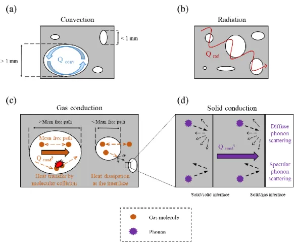
Porous materials are commonly used as insulation materials due to their very low density and high gas fraction which result in very low thermal conductivity. The effective thermal conductivity, λeff,of a porous materialis usually described as a sum of conduction, convection and radiation contributions (Equation 1)8,11–15.
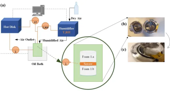
Figure 1. The modes of heat transport in porous materials. Heat transfer by:
a) Convection; b) Radiation; c) Gas conduction, including the coupling effects at the gas−solid interface and d) Solid conduction, highlighting diffuse and specular phonon scattering at interfaces. Taken from Apostolopoulou et al. 202016.
1.1.1 Conduction
The conductive heat flux, 𝑞⃗, through a material is generally described by Fourier’s Law (Equation 2)17–19.
𝑞⃗ = −𝜆∇𝑇 (2) where λ is the material’s thermal conductivity and ∇T is the temperature gradient. The conduction contribution to thermal conductivity is then classified into solid (λs) and gas (λg) contributions.
1.1.1.1 Solid Conduction
Heat in solids is transferred by electrons, mostly in metals, and phonons, predominantly in insulators and semiconductors20. Phonons are defined as
energy quanta that cause atomic lattice vibrations20–22. Stronger bonds (i.e.
covalent) favor heat transfer and phonon propagation more than weaker ones (i.e. hydrogen bonds, van der Waals interactions)21,23–26. There is no universal
equation to calculate the contribution of thermal solid conduction to thermal conductivity; however, one way is to apply the basic kinetic theory (Equation 3)18,22,24,27–29.
𝜆𝑠,𝑜= 1
3𝐶𝑉𝑣𝑙 (3)
where CV is the specific heat capacity at constant volume, v is the velocity of phonons which equals the speed of sound and l is the phonon mean free path. The mean free path of phonons is not always easy or possible to estimate, especially in systems with defects. There have been numerous computational attempts to improve the kinetic theory by incorporating defects, interfaces, grain boundaries or bonding strength22,28.
To determine the solid thermal conductivity in a porous material, several studies have used a variety of geometrical or density-related approaches11,12,15,30,31, as well as approaches that take into consideration the
sound velocity though the porous material (Equation 4)28,32.
𝜆𝑠= 𝜆𝑠,0 𝜌𝑎 𝜌𝑠,0
𝑣𝑎
𝑣𝑠,0 (4)
where λs,0 is the bulk solid thermal conductivity, ρa is the aerogel density,
ρs,0 is the bulk density, va is the speed of sound in the aerogel and vs,0 is the speed of sound in the solid.
Nanomaterials, consisting of nanosized particles, usually have a high number of interfaces which can serve as phonon scattering points22,30,33–35.
When phonons meet a boundary or an interface, they are either transmitted or scattered, the latter as specular or diffuse scattering24,33.Diffuse scattering
significantly influences heat flow, resulting in a lower thermal conductivity compared to specular scattering incidents. Diffuse phonon scattering due to a higher number of interfaces and grain boundaries is enhanced in nanomaterials compared to their bulk equivalent, resulting in higher interfacial thermal resistance and lower thermal conductivity22,30,33–35. In porous nanostructured
materials, solid conduction can be minimized not only because of phonon scattering at the solid−solid interfaces but also at the solid−gas interfaces27,30,36. Specifically, Coquard et al. showed that, in materials having
pores smaller than the phonon mean free path, diffuse phonon scattering at the solid boundary is significantly enhanced37.
The Kapitza resistance (Equation 5),22,38–40 which stands for the inverse of
the conductance, represents the resistance between grain boundaries and interfaces in a material. The influence of interfaces on the solid conductance can be expressed as:
𝜆𝑠= 𝜆𝑠,0 1+𝜆𝑠,0𝑅𝐾
𝑑
(5) where λs,0 is the bulk solid thermal conductivity, d is the particle size and
RK is the Kapitza resistance. Interfaces between two different solid materials with large differences in the phonon velocity and density can result in large Kapitza resistances33.
To determine the solid conduction contribution of a porous material experimentally, one can measure the effective thermal conductivity under vacuum and low temperature, to minimize both the gaseous and radiative heat transfer contributions28. Coquard et al., for instance, performed Monte Carlo
simulations to predict the solid thermal conductivity contribution of an open Kelvin cell model of a porous insulation material based on a cellulosic matrix in vacuum37.
1.1.1.2 Gas Conduction
The gas conduction is mainly described by collisions between gas molecules and it is usually the main contribution (more than 60%) to the effective thermal conductivity of porous materials due to their high gas fraction14,41. The main parameter influencing the gas conduction in a porous
material is the pore size. The pore size controls the occurrence and frequency of the molecular collisions observing the so-called Knudsen effect for nanosized pores, usually below 50 nm. The mean free path of air molecules is bigger than the pore size which significantly reduces the molecular collisions between the gas particles and therefore the gaseous thermal conductivity contribution. The Knudsen diffusion then occurs as the particles are more
likely to collide with the foam or aerogel walls than with each other42,43. In
general, having a porous material with small pores can both reduce the gaseous thermal conductivity contribution due to the Knudsen43 effect, and
lead to lower solid conduction contribution37. Xie et al. prepared a graphene
aerogel which exhibited a thermal conductivity of 5−6 mW m−1 K−1 at room
temperature under vacuum due to extensive phonon scattering within the graphene flakes and between them, even though graphene is a very good conductor36. One way to determine the gaseous thermal conductivity
contribution experimentally is to subtract the effective thermal conductivity under vacuum from the effective thermal conductivity under ambient pressure conditions14,28. The most common equation15,31,38,44–46 used to calculate the
gaseous thermal conductivity was first developed by Kaganer et al.47 and later
extended by Zeng et al.43 (Equation 6) to consider the specific surface area and
the aerogel density. 𝜆𝑔 =
𝜆𝑔,0
1+2𝛽𝐾𝑛 (6)
where λg,0 is the thermal conductivity of air in free space, β is a characteristic number equal to 2 for foams and aerogels, and Kn is the Knudsen number. The Knudsen number is the mean free path (Equation 7) of air molecules divided by the pore size43.
𝐼 = 1 √2×𝑃×𝜋×𝑑𝑔 2 𝑘𝐵×𝑇 + 𝑆×𝜌 𝛱 (7) where P is the pressure, dg is the diameter of a gas molecule, kB is Boltzmann’s constant, T is the temperature, S is the specific surface area, ρ is the density of the porous material and Π is the porosity. However, there are several recent studies which discuss the addition of one parameter to the gaseous conduction contribution, called the solid−gas coupling effects14,28,46,48. The solid−gas coupling effects represent the molecular
collisions occurring at the solid−gas interface and are dependent on the solid particle size as well as the pore size, and there have been attempts calculate their contribution14,28.
1.1.2 Convection
Convection is the natural or forced movement of a fluid which transports heat according to the fluid’s own velocity49. During natural convection,
buoyancy forces caused by temperature differences and thermal expansion are the main driving forces of the fluid’s motion. For forced convection, an external force is always required50. The Nusselt number expresses the ratio
between the convective and the conductive heat transfer contributions and has a value of 1 when only conduction occurs in the system (Equation 8)50,51.
𝑁𝑢𝐿= ℎ𝐿
𝜆𝑔 (8)
where h is the Nusselt number, L is the characteristic length and λg is the gas conduction contribution to thermal conductivity. However, in porous materials used for thermal insulation, the pore size is usually below the convective threshold of 1−4 mm, resulting in negligible convection 12,14,30.
1.1.3 Radiation
The radiation contribution to thermal conductivity depends on the experimental temperature, as well as on the thickness, density, and pore size of the tested material11. The most common equation used in the literature
includes a dependence on the ambient temperature to the third power (Equation 9) confirming that at low temperatures the radiative heat transfer becomes negligible.
𝜆𝑟𝑎𝑑= 16𝜎𝑇3
3𝐸𝑅 (9)
where σ is the Stefan−Boltzmann constant, T is the temperature and ER is
the Rosseland mean extinction coefficient. Obori et al. constructed a parametric open-pore model for CNF aerogels which described very well the experimental thermal conductivity for 0.3−1.4 v/v% solid CNF content30. The
model showed that the radiative heat transfer was comparable to or even higher than the solid conduction contribution at solid CNF concentrations below 0.6 wt%, while the gaseous heat transfer was the highest of all three. Under vacuum, the radiation contribution increased due to heat preferably travelling through the solid. However, at ambient temperature and pressure
conditions and as the solid content increased up to 1.4 wt% the radiation contribution was significantly lower since it varied linearly with ‘T3’37 and is
more dominant under vacuum14.
1.2 Insulation Materials
Polyurethane and polystyrene are fossil-based thermal insulation materials that are extensively used in buildings52. Polyurethane foams are produced by
a reaction between isocyanates and polyols and filled with an expansion gas (i.e. hydrofluorocarbon, CO2 or C6H12), and usually exhibit thermal
conductivities between 20 and 30 mW m−1 K−1 52–54. Expanded (EPS) and
extruded (XPS) polystyrene are made from small polystyrene spheres and melted polystyrene, respectively. Both EPS and XPS exhibit thermal conductivities usually between 30 and 40 mW m−1 K−1 and sometimes up to
45 mW m−1 K−1 for high-density insulation materials52,55. Both polyurethane
and polystyrene are hydrophobic, exhibiting good thermal insulation performance even at high moisture conditions52,54,56. Specifically, the thermal
conductivity of EPS with density of 16.5 kg m-3 increases from 37 to 51 mW
m−1 K-1 from dry to moisture-saturated conditions56.
Other common insulation materials used today include mineral wool, wood chips, and cork, which exhibit higher thermal conductivities and moisture sensitivities than polyurethane and polystyrene52,56. The thermal conductivity
for instance of mineral wool escalates significantly at high moisture contents, reaching even the high thermal conductivity value of 900 mW m−1 K−1 at
moisture-saturated conditions, which is 24 times greater than the value at dry conditions (=37 mW m−1 K−1)56. Wood-derived insulation materials, such as
wood chips and cellulose fibers, that are usually used in cavities are well-known hygroscopic materials as well, having thermal conductivities above 40
mW m−1 K−1 52,57.
The most recent development in the field of thermal insulation materials for buildings is the vacuum insulation panels (VIP) made of several metallized polymer laminate films entrapping fumed silica7,57,58. The thermal
conductivity of VIP can be as low as 3−4 mW m−1 K−1 but it degrades
gradually with time due to air diffusion within the layers. Furthermore, the installation of such materials is difficult, and it can impose irreversible damage
to the VIP, which can result in significantly higher thermal conductivity. The high cost and the difficulty to handle and install the VIP makes them challenging and unattractive to use7. Other materials are the phase-change
materials, which provide a thermal insulation capacity via cycles of endothermic and exothermic melting and solidification. The phase change materials are rather uncommon, and they have to be adjusted according to the specific climatic conditions and temperature ranges7.
1.3 Aerogels and Foams
In the literature there is a confusion between the definition of foams and aerogels. Lavoine et al. suggested that lightweight porous materials should be called aerogels if the pore size is less than 50 nm and foams if the pore size is larger than 50 nm59. However, the terms in literature are used many times
interchangeably which makes it difficult to compare different studies.
1.3.1 Processing Routes to Obtain Porous CNM Foams
and Aerogels
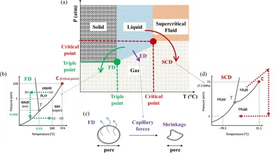
Figure 2. Common processing routes to obtain porous foams and aerogels. (a)
drying (SCD). (b) Phase diagram of water, the most common solvent used for sublimation. (c) Capillary forces during ED induce structural shrinkage. (d) Phase diagram of CO2, the most common supercritical fluid used. (b) and (d)
are adapted from Lavoine and Bergström, 201761.
The method used to remove the solvent from a dispersion to obtain a solid foam or aerogel defines the final structure. The most common ways to produce solid foams and aerogels (Figure 2a-d) are supercritical drying (SCD), freeze-drying (FD) and evaporative drying (ED) (oven/ambient)8,60.
To produce isotropic aerogels and foams, SCD, FD or ED have been used, whereas anisotropic aerogels are mostly produced by freeze-casting and FD.
1.3.1.1 Supercritical Drying (SCD)
During SCD (Figure 2a), the solvent (usually water) is substituted by a supercritical fluid to minimise the capillary pressure-induced stresses, present at a liquid/vapor interface, during the solvent removal, as these can lead to the collapse of the porous structure8,59,60. Carbon dioxide (CO
2) constitutes the
most common supercritical fluid (Figure 2d) used due to the low and accessible temperature and pressure conditions (31.3 °C and 72.9 atm). In most cases, an intermediate solvent exchange to ethanol is required as the supercritical fluid is immiscible with the original solvent. Some disadvantages of supercritical drying include its high cost and energy use, as well as its complexity. However, using SCD usually results in aerogels with small pore sizes (mesopore range, 2−50 nm), which reduces significantly the gaseous thermal conductivity contribution due to the Knudsen effect8,62–64.
1.3.1.2 Freeze-Drying (FD) and Freeze-Casting
The most common way to prepare solid foams and aerogels, especially from cellulose/CNF-based dispersions, is by FD62,65–70. FD involves the
sublimation of the frozen solvent which is usually water (Figure 2b). The sublimation reduces the capillary forces by inhibiting the formation of a liquid/vapor interface8,59,60,70. The freezing and solidification of a dispersion is
typically done by immersion in cold medium such as liquid nitrogen (Figure 3a). The rapid freezing includes homogenous freezing of the dispersion from all sides keeping the original dispersion structure intact, resulting in materials with 3D pore structure.
Figure 3. Freeze-drying of foams and aerogels. (a) Graphic illustration of
homogeneous freezing resulting in isotropic structures. (b) Graphic illustration of unidirectional freezing resulting in anisotropic structures modified from Apostolopoulou-Kalkavoura et al., 202171.
Instead of rapid solidification, one can use freeze-casting (Figure 3b) or ice-templating to slow-freeze the dispersions. In freeze-casting, the dispersion is unidirectionally frozen, which allows the ice growth to push the solid particles along the direction of the temperature gradient, yielding anisotropic structures with a honeycomb of tubular pores. The process conditions such as the freezing temperature and cooling rate determine the foam structure as well
as the pore size, with the latter being smaller as the cooling rate increases59,70.
Therefore, depending on the process conditions, it is possible to obtain aerogels with small pore sizes (<50 nm) or foams with larger pore sizes and even hierarchical pore structures (at least two main pore length scales; i.e mesopores and macropores). One advantage of the freeze-casting compared to rapid solidification is that the final porous structure is reproducible by controlling the process conditions, making it an excellent foam production procedure both in lab but also in industrial scale59. However, freezing and
freeze-drying are expensive and energy consuming, though less complex than SCD as no solvent exchange cycles are required.
1.3.1.3 Evaporative (Oven/Ambient) Drying (ED)
Compared to SCD and FD, ED in an oven or under ambient conditions is potentially a less expensive and energy-intensive route to solid porous materials. The main limiting factor of ED is that capillary-induced deformation (Figure 2c), cracks or even collapse of the porous structure can occur during evaporation of the solvent; these issues are greatly inhibited during SCD and FD. Therefore, the wet foam needs to have a robust structure which will withstand capillary forces, avoiding collapse. The most common ways to prepare wet foams include vigorous stirring, shaking, pouring, sparging or desorption in order to introduce gas bubbles in a dispersion72–74.
To avoid the coalescence of the gas bubbles several compounds are used to stabilize the air−solvent interface such as surfactants or particles (i.e. Pickering foams)59,75–77. Other ways to reduce cracking, shrinkage and
collapse during evaporative drying are to allow crosslinking between the solid particles, use a solvent other than water (i.e. ethanol) or to modify the particle surfaces59,64,75,78,79. Apart from the high shrinkage risk during ED, the need for
foam stabilization might entail a long process including the extensive use of chemicals, thus reducing the renewability and environmentally friendly character of for instance a cellulose/CNM foam. Furthermore, due to capillary forces, the pore sizes of the materials obtained by ED are larger than those obtained by SCD or FD, resulting in higher gaseous conduction contribution to, and overall higher, effective thermal conductivity. The solid conduction contribution is also enhanced in case of stronger bonding due to crosslinking, increasing once again the effective thermal conductivity.
1.3.2 Thermal Conductivity of Aerogels and Foams
Aerogels are a promising class of low-thermal-conductivity materials. The lowest thermal conductivity has been so far observed for isotropic silica aerogels, which can exhibit values as low as 12−15 mW m−1 K−1 under ambient
conditions8,9. Silica aerogels usually display mesopores, minimizing the
gaseous thermal conduction contribution significantly. However, silica aerogels are in general brittle, difficult to apply, and expensive; therefore they are not widely used despite their extraordinary thermal properties8. In
numerous studies, cellulose or CNMs have been added to silica aerogels in order to reduce their brittleness while maintaining their monolithic shape64,78,80–86. In most of those studies the thermal conductivity of the final
aerogels remained lower than that of air, or the so-called super-insulating level. However, it is worth noting that the temperature (T) and RH conditions are not always mentioned or controlled, making it difficult to compare the studies.
Interestingly, freeze-dried isotropic hybrid silylated silica/CNF aerogels with a CNF content of less than 10 wt% and a density of 130 kg m−3 displayed
a thermal conductivity as low as 13.8 mW m−1 K−1, which was only 1−2 mW
m−1 K−1 larger than the silica-only aerogel86. It is worth noting that isotropic
silica aerogels reinforced with 15 wt% short cellulose fibers exhibited thermal a conductivity of 15-16 mW m−1 K−1 after supercritical drying and 17 mW m−1
K−1 after ED ambiently, whereas the pure silica aerogel had a thermal
conductivity of 14 mW m−1 K−1 64,78.
During the past decade, there have been many attempts to prepare cellulose-only/CNM aerogels and foams, as cellulose offers great potential in the thermal insulation field due to its low thermal conductivity, low density, tunable surface chemistry and renewability. The best-performing isotropic aerogels or foams are made from TEMPO-oxidized CNF (TCNF) and have been reported by Kobayashi et al.63, Sakai et al.62, Jiménez-Saelices et al.87
and Chen et al.88 Kobayashi et al.63 prepared aerogels by SCD, whereas Sakai
et al.62 prepared both aerogels by SCD and foams by FD, and Jiménez-Saelices
et al.87 used only FD, achieving a thermal conductivity as low as 18 mW m−1
K−1 at 295−296 K and 50% RH. Chen et al. prepared aerogels by FD and
reported a thermal conductivity of 16 mWm-1K-1, but at unspecified
others88. All these high-performing aerogels had a 3D porous network with
mostly small nanosized pores, while the foams had closed microsized pores. Furthermore, some studies have investigated the effect of mixing various CNMs and cellulose fibers65 or adding other non-cellulosic components68,77 in
the CNF/cellulose aerogels or foams. For instance, Pickering TCNF−hexadecane (20 kg/m3 at 295 and 50% RH) and CNF−10% nanozeolite
aerogels exhibited thermal conductivities of 18 mWm-1K-1, the same value as
for the best-performing TCNF-only aerogels. Furthermore, a multiscale study mixed CNF with bleached cellulose fibers, achieving a thermal conductivity as low as 22 mW m−1 K−1.
Wicklein et al. and Kriechbaum et al. reported the lowest radial (perpendicular to the fiber direction) thermal conductivities for anisotropic CNF- and TCNF-only foams respectively, which were as low as 18 mW m−1
K−1 while the corresponding axial (along the fiber direction) value was as high
as 150 mW m−1 K−1 at 296 K and 50% RH38,89. Interestingly, Wicklein et al.
also prepared also composites of TCNF, graphene oxide (GO), boric acid (BA) and sepiolite (SEP), which exhibited a radial thermal conductivity of 15 mW m−1 K−1 and an axial one of 170 mW m−1 K−1 38. Furthermore, Li et al.
prepared anisotropic nanowood and the radial thermal conductivity dropped from 107 mW m−1 K−1 for basswood to 32 mWm-1K-1 for nanowood and the
axial dropped from 347 mWm-1K-1 for basswood to 56 mW m−1 K−1 for
nanowood at 298 K and 20% RH90.
The major challenge for the future market of thermal insulation materials is then to keep the low super-insulating thermal conductivities of silica aerogels but also to reduce the cost and increase the robustness of the future aerogels8,52. Despite the recent developments in the field of thermal insulation
and the studies on cellulose and CNMs, most of the studies disregard the effect of moisture on the thermal conductivity and fail to accurately report the experimental conditions used for the measurements. As cellulose is highly hygroscopic, it is crucial to investigate the impact of moisture uptake on the thermal insulation performance. Furthermore, comparing the variations in thermal conductivity between studies, there is a need to understand the heat transfer mechanism and the parameters which play important roles in tuning and controlling thermal transport both on the nano- and the macroscales.
1.4 Thermal Conductivity Measurement Techniques:
Benefits and Drawbacks
Thermal conductivity can be experimentally measured either by steady-state or transient techniques91. The steady-state techniques require a large
steady-state temperature gradient and measure heat flow across a sample of known thickness18,49,92,93. The guarded hot plate (Figure 4a)10,28,46,56,81,86,94–98
and the heat flow meter apparatus30,64,78,80,83,84,99–101 are both steady-state
techniques that are commonly used to determine the thermal conductivity of thermally insulating materials. The steady-state techniques are very accurate and require simple experimental calculations but obtaining a steady-state temperature gradient across the sample requires a long wait. Furthermore, large samples are usually required and the contact between the thermocouple and the sample can sometimes create errors.
Figure 4. Common thermal conductivity steady state and transient techniques.
(a) Guarded hot plate and (b) Hot Disk showing the disk-like transient plane sensor (TPS). (b) Taken from Apostolopoulou-Kalkavoura et al. 202171.
The transient techniques measure the heat dissipation when a heat pulse hits the sample. They usually require shorter times and can measure smaller samples than steady-state techniques18,92,93. The hot wire
method15,31,37,43,48,49,82,102–105 and the hot strip method29,66,67,77,106,107 are both
very common transient techniques used to determine the thermal conductivity of porous thermally insulating materials using a linear and a planar heat source. The transient plane source (TPS) or hot disk (Figure 4b)40,69,75,89,108–117,
using a spiral disk sensor between two identical sample pieces, is the most recent development of the hot wire and hot strip techniques92,118. In general,
the effect of the contact between the sensor and the sample can be corrected for the transient techniques compared to the steady state but a good contact is prerequisite for a reliable measurement. The laser flash46,90,95,119,120 is also a
transient technique but it measures the thermal diffusivity resulting in an indirect determination of the thermal conductivity49,92. However, the laser
flash minimizes the thermal contact issues as it uses a non-invasive laser beam. For thin films one can also use either the 3ω technique20,121–123 or the
time-domain thermoreflectance (TDTR)124,125 which are both transient
methods93.
1.5 Cellulose: Structure and Intrinsic Anisotropy
Cellulose, being the dominating component of wood (Figure 5a-b), algae, tunicates, and cotton, is an abundant and renewable raw material with great potential for thermal insulation since it exhibits low thermal conductivity and tunable surface chemistry126–130. The cellulose molecule is a linear-chain
biopolymer consisting of glucose molecules and the repeating unit consists of two anhydroglucose rings linked through a covalent bond from the oxygen on C1 of one glucose ring to C4 of the other of glucose ring (1–4 glycosidic bond)131. Cellulose naturally exists in two crystalline forms: cellulose I
α,
which has a one-chain triclinic unit cell, and cellulose Iβ, which has a
two-chain monoclinic unit cell126,132–134.
Natural cellulose can be converted via various chemical treatments to cellulose II, III and IV, which can be used in other applications such as textiles and cellophane134–136. Interestingly, cellulose possesses an intrinsic anisotropy
(Figure 5c) which features covalent bonds and intramolecular hydrogen bonds along the c-axis and weaker interactions such as van der Waals and intermolecular hydrogen bonds along the a and b axes126,129,135,137. The intrinsic
anisotropy of cellulose crystals has been also confirmed by examining their thermal expansion coefficient, which is much higher along the a-axis than along the covalently bonded c-axis126. Along the c-axis the covalent bonds
restrain the thermal expansion while the less tightly fixed interfibrillar hydrogen bonds in the radial direction are more sensitive to temperature variations129,138. Wada and Altaner et al. observed from X-ray diffraction and
Fourier-transform infrared spectroscopy experiments respectively that the interfibrillar hydrogen bonds of cellulose become weaker upon increasing
temperature, resulting in an anisotropic thermal expansion along the three axes of cellulose129,138.
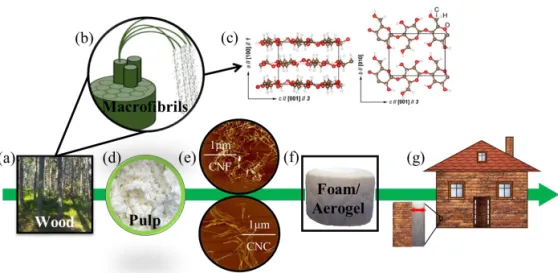
Figure 5. Wood cellulose for thermal insulation applications. (a) Wood: the
major cellulose source. (b) The hierarchical structure of wood fibers. (c) The anisotropic structure of cellulose Iβ. (d) Wood pulp after processing. (e) Characteristic AFM pictures of cellulose nanomaterials (CNF and CNC). (f) CNM based foams or aerogels. (g) Thermal super-insulation applications. (c) is adapted from Apostolopoulou et al. 202016.
1.5.1 Cellulose Nanomaterials (CNM)
The CNMs can be distinguished into CNF and CNC and can be produced through different mechanical and treatment pathways from cellulose fibers134,139. Wood, which constitutes the major source of cellulose for
producing cellulose nanomaterials, has a hierarchical structure in which the cellulose fibers consist of cellulose microfibrils (Figure 4b) in bundles and each microfibril consists of 30−40 cellulose chains. The cellulose fibers have widths of 20−30 μm and lengths of 1−3 mm and the cellulose microfibrils, which are commonly called CNF (Figure 5e), usually have widths of 3−4 nm and lengths around 2 μm. The CNFs are usually long flexible fibers with kinks and high aspect ratios. The CNCs (Figure 5e) are rigid rods with lower aspect ratio than CNF but higher degree of crystallinity139,140.
1.5.2 Cellulose Nanofibrils (CNF)
The deliberation of CNF can be accomplished by mechanical disintegration in microfluidizers, high-pressure homogenizers, grinders, blenders, aqueous counter collision or screw-type extruders. Different parameters such as the level of desired defibrillation, the pretreatments of cellulose or the presence of hemicellulose will define the proper mechanical treatment for each case. Using only mechanical means for defibrillation usually results in fibrils with diameters over 10 nm. To enhance the fibrillation, to introduce desired properties such as surface charge cellulose and/or to improve colloidal stability, cellulose is usually subjected to chemical pretreatment139.
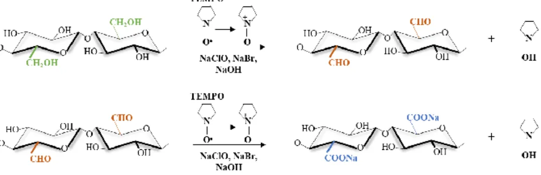
Figure 6. Cellulose Iβ unit cell. (a) Initial chemical structure and (b)
TEMPO-oxidized chemical structure including the oxidation of the −CH2OH located at
C6 to −COO−Na+.
Common cellulose pretreatments are enzymatic hydrolysis, carboxymethylation and TEMPO (2,2,6,6-tetramethylpiperidine-1-oxyl radical)-mediated oxidation. During carboxymethylation, certain −OH groups are replaced by −CH2COO− while during TEMPO-mediated oxidation (Figure
6a,b) the −CH2OH groups located on the C6 of the anhydroglucose unit are
converted to −COO−, thus introducing negative surface charges139–141.
However, during enzymatic hydrolysis, the surface glycoside bonds are partially cleaved to enhance the defibrillation of CNF. Combinations of chemical and mechanical treatment methods can result in high degree of fibrillation and thus in fibrils with smaller diameters (3−4 nm)139.
1.5.3 Cellulose Nanocrystals (CNC)
In the most common synthesis of CNCs, cellulose pulp is treated with H2SO4, which partially hydrolyzes and removes the disordered regions of
cellulose to leave a highly crystalline material139,142. Other acids such as HCl
may be also used for the hydrolysis, introducing different surface properties and other aspect ratios143. Interestingly, the CNC dispersions exhibit unique
properties of self-assembly in chiral nematic liquid-crystalline phases above a critical concentration142,144.
1.6 Thermal Conductivity of Wood and Cellulose
Cellulose Iβ has an intrinsic anisotropy due to stronger bonding along than perpendicular to the cellulose chain (see Section 1.4). The intrinsic anisotropy caused by the presence of covalent bonding along the c-axis but not the b- and
a-axes of the cellulose crystals is translated into thermal anisotropy because
phonon propagation is directly correlated with the strength and density of atomic bonding21,145–147. The weaker bonding limits phonon propagation,
resulting in lower thermal conductivity values in the radial direction19,21,23,145,148–152.
Wood, which is a great source of cellulose, exhibits an intrinsic thermal anisotropy (up to 1.7109) and thermal conductivity estimations for different
wood types confirm that thermal conductivity is higher along the covalent longitudinal direction (323 mW m−1 K−1 for birch at 294 K), parallel to the
grain (λa), than along the transverse (λr) direction (214 mW m−1 K−1 at 294
K)153. Other studies have estimated the anisotropic thermal conductivity of
wood cellulose fibers154 (1040 mW m−1 K−1 and 260 mW m−1 K−1) or wood
fibers153 (766 mW m−1 K−1 and 430 mW m−1 K−1), confirming large anisotropy
in all cases. Of course, wood is less anisotropic than pure cellulose as it contains hemicelluloses, lignin and extractives in a hierarchical structure which may not possess the same intrinsic anisotropy as cellulose.
The anisotropic thermal conductivity of cellulose Iβ crystals has been
investigated by simulations resulting in values of about 900, 240 and 520 mW m−1 K−1 along the c (λ
a), a, and b (λr) axes, respectively at 298 K, with very little temperature sensitivity over a wide range (73–573 K)19. Furthermore, the
thermal conductivity of a single CNC particle estimated by MD simulations was 5700 mW m−1 K−1 along the covalent backbone compared to the 720 mW
m−1 K−1 perpendicular to the chain.
To confirm this high anisotropy experimentally, Diaz et al. prepared bulk films consisting of aligned CNC particles, which exhibited thermal conductivities of 530 and 220 mW m−1 K−1 along (λ
a) and perpendicular to (λr) the fibers’ direction. The difference between the thermal conductivity of single CNC particles and bulk CNC films can be explained with the interfacial thermal resistance estimated by Diaz et al. to be 9.4−12.6 m2 K GW−1 155.
Other attempts to measure the anisotropic thermal conductivity of various cellulosic films have shown that the thermal conductivity and the degree of anisotropy are affected by the cellulose type, crystallinity, crystallite size, and of course the degree of the particles’ alignment. For instance, among the different CNM-based nanopapers tested by Uetani et al., the tunicate nanowhiskers (TNWs) exhibited the largest anisotropy while the TEMPO-oxidized Sugi cellulose nanofibril (TOSNF) the lowest (twofold)156. The
nanopapers with aligned TNWs had thermal conductivities of 2500 mW m−1
K−1 and 300 mW m−1 K−1 in the directions along (λ
a) and perpendicular (λr) to the fibers, respectively18. This eightfold anisotropy is similar to the anisotropy
measured for single CNCs by Diaz et al., confirming the large intrinsic anisotropy of cellulose18,145,156. Another study included the preparation of
epoxy resin and CNF/epoxy resin nanocomposite; here, the addition of CNF introduced a fivefold anisotropy thermal conductivity, with values of 1100 and 230 mW m−1 K−1 along (λ
1.7 Scope of the Thesis
As fossil fuels are depleted and CO2 emissions are increasing, there is a
pressing need to implement more renewable and eco-friendly thermal insulation materials. Cellulose is an emerging material which has high potential, but it is necessary to investigate in depth the CNM/cellulose-based foam/aerogel processing as well as heat transfer mechanisms.
Taking into consideration the hygroscopic character of many insulation materials and especially those made from biopolymers such as cellulose, the first goal of this thesis was the development of a measurement cell in which the temperature and relative humidity can be carefully controlled while thermal conductivity is measured. However, performing measurements in such a cell is not straightforward and many parameters had to be investigated and optimised (i.e. the wet density, the specific heat capacity and/or the volumetric shrinkage).
The second goal of this PhD thesis was to investigate the effect of relative humidity on thermal conductivity and understand the underlying mechanisms that influence heat transfer in both isotropic and anisotropic CNM-based foams. The effects of density, nanoporosity, degree of alignment, degree of crystallinity, and fibril dimensions on the thermal conductivity and moisture uptake of anisotropic CNM-based foams have been investigated and modelled. Specifically, one important aim was to estimate the importance of thermal boundary conductance and phonon scattering on the nanoscale for the effective thermal conductivity of the anisotropic foams. The research work has combined experimental measurements with theoretical calculations and molecular simulations, which mainly were performed by our collaborators. The thermal conductivity of isotropic CNF-based foams was also investigated and compared with expanded polystyrene insulation it was also attempted to model it following an engineering approach as function of the moisture uptake. The moisture uptake, being a crucial parameter, was further investigated in relation to temperature and crystallinity by a combination of experiments and molecular simulations performed by our collaborators.
To this end, this thesis sums up the dominant thermal conductivity contributions and paves the way for setting up the foundation of correct reporting of the thermal conductivity measurements of hygroscopic CNM foams.
2 Preparation of Materials
2.1 Preparation of Mechanically-ground CNF and
TEMPO-mediated Oxidized CNF (TCNF)
For papers I, III and IV, the starting material was a never-dried sulfite softwood cellulose pulp (Domsjö dissolving Plus) provided by Domsjö Fabriker AB (Aditya Birla, Domsjö, Sweden). For paper V, the starting material was powdered Cladophora cellulose and provided by FMC Biopolymer.
Figure 7. Simplified two-step reaction scheme in which TEMPO oxides the
primary alcohol to give an aldehyde that is further oxidized to give a carboxylic group.
TEMPO-oxidized cellulose nanofibrils (TCNF) were prepared as previously reported158 using the TEMPO/NaBr/NaClO system (Figure 7).
Before the oxidation, the cellulose pulp was washed with 0.01 M HCl solution and deionized water until the conductivity of the filtrate dropped below 5 μS. The washed pulp together with TEMPO (0.016 g per g of dry pulp) and NaBr (0.1 g per g of dry pulp) were mixed with deionized water and stirred. NaClO was added dropwise while the suspension was stirred. The pH of the suspension was monitored, and 0.5 M sodium hydroxide solution was added dropwise to maintain the pH at 10 during the entire oxidation reaction. For papers I−V different TCNF were prepared by varying the NaClO content from 2.5 to 10 mmol per gram of cellulose as well as the duration of the oxidation
(up to 4 h) to obtain different charge densities. The next step includes washing of the oxidized pulp with deionized water during filtration until the filtrate has a conductivity below 5 μS.
Figure 8. Simplified reduction reaction of the remaining aldehydes into
primary alcohols.
For papers I and III, any residual aldehydes and ketones were reduced to primary alcohols (Figure 8) by adding 0.1 g of NaBH4 per gram of cellulose
to the TEMPO-oxidized cellulose pulp suspension at pH 10 under stirring for 3 h159. After the reduction reaction, the pulp was again washed with deionized
water until the conductivity was lower than 5 μS. For paper IV, no reduction reaction was performed.
For papers I and III, the TEMPO-oxidized cellulose pulps and the untreated pulp were grinded by a supermasscolloider grinder (Model MKZA10-15J, Masuko Sangyo Co., Ltd, Japan) equipped with non-porous grinding stones containing silicon carbide (Disk model MKE), using a gap clearance of −100 μm at a motor frequency of 30 Hz obtaining TCNF and CNF, respectively. For paper IV, the TEMPO-oxidized pulp was disintegrated by passing the dispersion four times through the 400-μm and 200-μm chambers of a high-pressure (1,600 bars) Microfluidizer (M-110EH, Microfluidics)75.
The mechanically treated CNF are referred to as CNF19 in paper I with 19
representing the CNF diameter in nm. The TCNFs used in paper I are referred to as CNF2.3 and CNF4.4,where 2.4 and 4.4 are the diameters of the TCNF
particles in nm. The TCNF used in paper III is referred to in the paper as ‘TCNF’ and the TCNF used in papers IV and V are referred in the papers as ‘CNF’.
2.2 Preparation of CNC and TEMPO-mediated
Oxidized CNC (TCNC)
Two types of CNC were used in this thesis. For paper II, the commercial Celluforce CNC powder was selected and dispersed in deionized water using a mechanical stirrer obtaining a dispersion with 4.5 wt% concentration. To obtain higher or lower concentration dispersions we upconcentrated the initial dispersion using a rotary evaporator or diluted it with deionized water. For paper III, the TEMPO-oxidized CNC (TCNC) were prepared by acid hydrolysis (HCl 2.5 M) of the TCNF prepared with 10 mmol g−1 of NaClO for
4 h at 105 °C. The TCNC were obtained by. The HCl was used to keep intact the surface chemistry of TCNF, as previously reported143. To obtain a
thoroughly clean final material, the TCNC were centrifuged and dialyzed against deionized water.
2.3 Preparation of Carboxymethylated CNF (CMCNF)
The CMCNF was prepared by our collaborators following a procedure described before160,161. Briefly, the cellulose fibers were immersed in ethanol
and then filtered, and this process was repeated three times to exchange water to ethanol. The fibers were soaked in a solution of 0.3 g monochloroacetic acid in isopropanol 15 ml for 30 minutes. Then the fibers were placed in a solution of NaOH, methanol and isopropanol at 82 °C. The carboxymethylation lasted for 60 min and was followed by deionized water, 0.1 M acetic acid, and deionized water filtration steps. To convert the pulp into the Na+ form, the treated fibers were immersed for 30 min in 4 wt%
NaHCO3(aq) and post-filtered with deionized water. The carboxymethylated
pulp was disintegrated in a high-pressure microfluidizer (M-110EH, Microfluidics) by a single pass through the 400-μm and 200-μm chambers and four times through the 200- and 100-μm chambers. Finally, the material was sonicated and centrifuged.
2.4 Preparation of the CNF@Al‑MIL‑53 Nanofibers
For paper V, the CNF@Al‑MIL‑53 nanofibers were prepared by our collaborators by growing continuous Al‑MIL‑53 metal−organic framework (MOF) layers on ultrafine CNFs via interfacial reactions, as has been described162. Briefly, TCNF with a charge density of 1.3 mmol COO− g−1 of
cellulose, made from Cladophora cellulose extracted from algae, was firstly ion-exchanged with Al3+ and surface-modified with the surfactant
polyvinylpyrrolidone (PVP) to regulate the growth and crystallization of MOFs. Then a solution of 0.75 g metal salt (aluminum nitrate nonahydrate, Al(NO3)3·9H2O) in 10 ml water and a solution of 0.21 g of the organic ligand
(disodiumterephthalate, Na2BDC) in 10 ml water were added in the TCNF
suspension dropwise while stirring.
2.5 Preparation of Anisotropic Foams by
Freeze-Casting
Anisotropic CNF, TCNF, CNC or TCNC foams for papers I−III were prepared by unidirectional ice templating, also called freeze-casting38,70, from
the corresponding dispersions. For papers I and III, the dispersions of CNF, TCNF or TCNC were diluted to 0.5 wt% in DI. For paper II, the the dispersions of CNC were adjusted to the desired concentration. Teflon molds 4 cm in diameter with copper bottom plates were filled with 30 mL of CNM dispersion and placed in contact with a dry ice plate, allowing unidirectional freezing, with cooling rate 3 K min–1,of from the bottom to the top. The final
dry foams were obtained by ice sublimation at 0.024 mbar and room temperature (RT) for four days using a freeze-dryer (Christ Alpha 1-2LDplus, Germany).
2.6 Preparation of Isotropic foams
In this thesis two different types of isotropic foams or aerogels are examined, the CNF−polyoxamer foams and the CAM (CNF−AL-MIL-53) foams. The CNF−polyoxamer foams were prepared by mixing the TCNF