V¨
aster˚
as, Sweden
Thesis for the Degree of Master of Science in Engineering - Robotics
30.0 credits
MOTOR SYSTEM DESIGN FOR
LARGE UAV
Daniel Hedlund
dhd11001@student.mdh.se
Examiner: Mikael Ekstr¨
om
M¨
alardalen University, V¨
aster˚
as, Sweden
Supervisor: Mirko Senkovski
M¨
alardalen University, V¨
aster˚
as, Sweden
Supervisor: Jakob Brynolf,
M¨
alardalen University, V¨
aster˚
as, Sweden
Abstract
This thesis investigates the viability of creating a fully electrical motorsystem for a large UAV capa-ble of VTOL. As of today only relatively small UAV’s use fully electrical motors as their only source of propulsion, larger UAV’s have to rely on more traditional combustion or jet engines. The reason for this is the low energy density of modern batteries compared to petroleum and diesel, even with high efficiency standards on electric motors, this means that UAV’s relying only on electric motors will have a very short flight time and thus short operational range. To get around this different methods that aircraft use to achieve VTOL flight was investigated as well as different methods for extending the flight time. The resulting UAV will combine the design of normal quadrocopters and modern sailplanes to create a UAV capable of gliding long distances to increase the range. Several different motors where considered for the motor system and out of these the EMRAX 208 was chosen. For the propeller a size of 68 inch was chosen with a pitch of 28 inch, the specific propeller used for the thesis was two Powerfin f-blades mounted on an apex hub. Several different batteries where also considered to poever the motors, the chosen battery is the LE 5000 7S. To control the motors a Gen5-S9 ESC whas chosen, one is needed for each motor. Using these components, the weight of the cargo and an estimated weight of the body the total weight of this UAV is estimated to be approximately 482 kilograms, the calculated operational range is 11.25 kilometers.
Table of Contents
Glossary 4 1 Introduction 5 1.1 Motivation . . . 5 1.2 Requirements . . . 5 1.3 Problem Formulation . . . 6 1.4 Research . . . 6 2 Background 7 2.1 VTOL . . . 7 2.1.1 Tiltrotor . . . 7 2.1.2 Tiltwing . . . 7 2.1.3 Gyroplanes . . . 8 2.1.4 Fan-in-wing . . . 8 2.1.5 Tail Sitter . . . 8 2.1.6 Vectored Thrust . . . 8 2.2 Exampel Aircraft . . . 8 2.2.1 V22 Osprey . . . 8 2.2.2 Canadair CL-84 . . . 9 2.2.3 Project Zero . . . 9 2.2.4 Joby S2 . . . 9 2.2.5 Firefly 6 . . . 9 2.2.6 LightningStrike . . . 9 2.2.7 Arcturus Jump 20 . . . 102.3 Motor and Propeller Calculations . . . 10
2.3.1 Thrust . . . 10 2.3.2 Energy . . . 11 2.3.3 Propeller Efficiency . . . 11 2.3.4 Torque . . . 12 2.4 Batteries . . . 13 2.5 Increasing Range . . . 13 2.5.1 Sailplanes . . . 13 3 Method 14 3.1 General . . . 14 3.2 Mechanics . . . 14 3.2.1 Design . . . 14 3.2.2 Body . . . 14 3.2.3 Wings . . . 15
3.2.4 Motor and Propeller . . . 15
3.3 Electronics . . . 17
3.3.1 Power Distribution . . . 17
3.3.2 Battery . . . 17
3.3.3 Electronic Speed Control . . . 18
3.3.4 Cables . . . 19 4 Results 20 4.1 Design . . . 20 4.2 Components . . . 20 4.2.1 Propeller . . . 20 4.2.2 Motor . . . 20 4.2.3 Batteries . . . 20 4.2.4 ESC . . . 21 4.3 Performance . . . 21 4.3.1 Weight . . . 21
4.3.2 Range . . . 21 5 Future Work 23 6 Conclusion 24 7 Acknowledgments 25 References 27 Appendix A Appendix 28
A.1 VTOL Methods . . . 28 A.2 Example Aircraft . . . 31
Glossary
CTOL Conventional Take Off and Landing. 7
ESC Electronic Speed Controler. 17,18, 19,20,21
FEM Finite Elemental Method. 16,17
MCM MCM refers to one thousand circualr mils which is a wire gauge that measures the are of the circle of the wire. The unit is mil which is one thousandth of an inch. 19
PDB Power Distribution Board. 17
STOL Short Take Off and Landing. 5
STOVL Short Take Off and Vertical Landing. 5,7
thermals A thermal column is a rising column of air in the earths lower atmosphere. Thermals are created by uneven heating of the earths surface and as the hot air rises updrafts are created. 13,23
UAV Unmanned Aerial Vehicle. 5,6,8,9,11, 13, 14,15,16,17,20,21,22,23,24
V/STOL Vertical/Short Take Off and Landing. 7
1
Introduction
There are many methods and designs for achieving VTOL (Vertical take-off and landing) for aircraft, they have advantages and disadvantages. The motor system for these designs will vary depending on the number of motors, their placment, the position and look of the wings and the method of which flight is achieved. The purpose of this thesis is to find the optimal VTOL
method for the UAV (Unmanned Areial Vehicle) project and to design the motor system. The most prominent methods forVTOLflight are tiltrotor, tiltwing, fan-in-wing and vectored thrust. Tiltrotor is a method that uses tilting rotors to achieveVTOLand is probably the most common method, it is relatively straight forward and has proven to be reliable both in vertical and horizontal flight. Tiltwing is not as popular, this method uses fixed motors on a tilting wing and this is often not as reliable since the tilting wing will be less stable then a fixed wing. Also the tiltwing method is usually less stable during vertical flight since the rotors are fixed on the wing and thus will always rotate at the same angle, this limits control during vertical flight. However development in control systems has allowed tiltwing aricraft to achive good control during vertical flight since the throttel of individual rotors can be changed during flight to compensate. The idea behind fan-in-wing is to place the propellers inside the wings, this reduce drag and protects the propellers. By itself this method is not very good forVTOL, its vertical flight capabileties are excelent since it behaves much like a multirotor or helicopter. But during horizontal flight the entire aricraft has to tilt forward to get any forward thrust, this method is limited in speed and efficiency much like a helicopter. But this method can be combined with either tiltwing or tiltrotor to creat a hybrid craft that will get some of the advantages of both. The fan-in-wing method will however increas the complexity of the aircraft by a fair margin. The last method is vectored thrust, it uses jet engins with nuzzels that can rotate to point downwards for vertical flight.
1.1
Motivation
M¨alardalen university (MDH) wants to creat a UAV that is capable of delivering up to three Naiads,[1], to a remote location, this project has been in the works for several years and have this far been worked on by students in the robotics and embeded systems programs, as part of the robotics project course. Thus far two smaler models of theUAVhave been designed and built and a control system has been tested on these two models, [2], [3]. These have both been down scaled and both have had very limited flight time and if they where to be scaled up to the appropriate size theUAVwould not be capable of performing its required duties. Thus the aim is to develop a motorsystem that will allow theUAVto performe these duties.
1.2
Requirements
There are several limitations and requirements that will influance the decision making these include. • TheUAV must be capable of true vertical take-off and landing, STOL (Short take-off and
landing) orSTOVL(Short take-off and vertical landing) is not good enough.
• The UAV should be able to land and take-off on both water and on the ground, this can affect the design of the wings and thus the placment of the motors.
• The UAV should be able to carry upp to three Naiads each weighing approximately 33 kilograms, so 100 kilograms in total.
• TheUAVshould have electrical motors that draw power from a battery. • TheUAVshould be able to fly like a multirotor during vertical flight
• The target range of theUAVis 25 kilometers, the minimum range is 5 kilometers.
The first item impies that the UAVshould be capable of landing and taking-off in a simillar maner to a helicopter, however it should also be able to fly horizontally simmilar to an airplane and with the advantages that this type of flight entails. This menas that theUAVwill need wings to provide static lift.
The second item is not very relevant since the design of the body is not part of this thesis. However the wings must be placed so that the tips of the wings do not risk dipping in to the water so they should be placed as high up on the body as possible. The risk of this occuring could be further reduced should pontoons be used in the body design in the future.
The third item is fiarly self explanatory, theUAV should be able to carry approximatley 100 kilograms of cargo and should have a cargo hold capable of storing this cargo. This is relevant since this will add extra weight and the body needs to be large enough to house the cargo.
The fourth item simply states that the UAVmust use electrical motors fueld by batteries as its only active prupulsion system.
The fifth item aims to keep the UAVas a drone that uses several propellers that provide lift to achieve a stable and highly controlable flight.
The last item is both a goal and a requirment, 5 kilomiters was stated as the minimum range for theUAVto be able to performe its intended function. The target of 25 kilomters is the range that this thesis should aim for.
1.3
Problem Formulation
TheUAVshould be able to start without a runway and be powered entierly by a battery. Prob-lems that are expected to appear during the design process are, choosingVTOL method that is best suited for such an aircraft and gives the best performance with a focus on minimizing fule consumption to extend the range of theUAVbut speed and maneuverability should also be con-sidered. Choosing rotor and wing placment that will give the greatest stability and control while also allowing the aircraft to land and take-off on water and land. Choosing electrical motors that provied enough lift to carry the aircraft and the cargo while also giving theUAV sufficient flight time. Designing a power system that will give the best flight time while still leaving space on the
UAVfor cargo and the control system.
There are essentialy two main parts to the design process, first mechanical part which will include the exact placement of the wings, they can be place higher and lower on the body, the angle wich the wings will be placed and the general shape and size. The placment of the rotors on the wings is also in the mechanical part. The second is the electronics part, this is the main part and will include choosing the type of motors that will be used, the power distribution board, power supply unit, electronic speed controler.
1.4
Research
While theUAVproject has a set of goals that this thesis aims to fulfill, the scientific part of this thesis is will need to be adressed as well. The research aspect of the thesis is to investigate the viability of creating a fully electric motor system for a largeUAV, the actual size and weight will be adressed later in the report.
2
Background
The background section will explain the state of the art. Section2.1will explain the general theory behind the methods of achievingVTOLflight, section2.2will give some examples of airplanes and drones capable of VTOL. These are necessary to give a general understanding of how VTOL
aircraft work. Section 2.3 and onwards is on subjects that are directly related to designing the motor system.
2.1
VTOL
There are many types of aircrafts that are capable ofVTOLand they use several different methods to achieve this. The most common and well known aircraft that is capable ofVTOL is of course helicopters, they come in different shapes and sizes but are generally classified as having one or two big rotors on top of the aircraft that delivers downward thrust and thus lift the aircraft straight up. The tilt of the aircraft can be changed to provide forward thrust as well, this method is however limited in speed and requires the whole aircraft to tilt. Thus this thesis will focus on airplanes that are capable ofVTOL. Normally airplanes are only capable of CTOL(Conventional take-off and landing) which requires a runway of significant length to accelerate until the lift provided by the wings allows the aircraft to take-off. This in turn gives airplanes faster and more fuel efficient flight. But sometimes it would be preferable if an airplane could take-off without a long runway and thus several methods have been developed that allow airplanes to performSTOVL,
V/STOL(Vertical/short take-off and landing) and even actualVTOL. There are several advantages to having an aircraft that can perform VTOL, the largest being that you can land and take-off virtually anywhere, but also that you are able to hover in place and it might even help to maneuver through difficult areas. The main reason for having an airplane that can perform VTOLis that you can take advantage of the faster and more efficient horizontal flight capabilities.
There are a number of ways that an airplane can performVTOL, most have different advantages and drawbacks and they will be discussed in this section.
2.1.1 Tiltrotor
A tiltrotor aircraft achievesVTOLby the way of tilting the rotors, see figure5 in the appendix, when the aircraft is in vertical flight mode the propellers point up and as the aircraft is changing from vertical to horizontal flight the propellers are rotated forward, some models are capable of rotating their propellers independent of eachother. These types of aircrafts have fixed wings that provide lift during horizontal flight and are often fitted with control surfaces on the wings to provide control and stability. The main advantage of tiltrotor aircraft is that they have vertical flight performance comparable to helicopters while still keeping more efficient and faster horizontal flight [4]. Some disadvantages compared to other VTOL methods is a complex motor system, the propellers have to be rotated which requires extra complexity. The wing design and rotor placement is also limited since the rotating propellers must be place so they don’t interfere with the rest of the aircraft. Lastly the transition time between vertical and horizontal flight is longer than some of the other methods [5].
2.1.2 Tiltwing
Tiltwing aircraft have fixed rotors and a wing capable of tilting, see figure6 in the appendix, the opposite of the tiltrotor method. During horizontal flight these perform just like a normal airplane but during vertical flight it is not as stable as other methods [6]. Since the rotors are fixed on the wing they will tilt along with it and this limits control during vertical flight and increases the transition time from vertical to horizontal flight. Since the wing is not fixed it is less stable which can causes problems. One advantage is that the motor system is simpler since it is only the wing that tilts and not several different components [7].
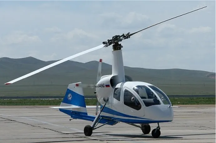
2.1.3 Gyroplanes
Gyroplanes are a little different, the idea behind this method is to take advantage of something called autorotation. This is a state of flight where the main rotor system turns by the action of the air moving through the rotor. This generates lift and is mostly used for safe landing in the event of an engine failure. For gyroplanes however it is one of the main advantages for reducing fuel consumption during horizontal flight. Gyroplanes use a large main rotor placed on top of an airplane, see figure7 in the appendix,crating something of a helicopter airplane hybrid. The large main rotor will be used for vertical flight and during horizontal flight it will be autorotating to generate extra lift. The aircraft usually has one or two rotors placed horizontally to provide forward thrust during horizontal flight. Some advantages with this method include simple design, good vertical flight performance, smooth and fast transition from vertical to horizontal flight and that autorotation can help with landings should engine failure occur. Some problems with this method include the wings of the aircraft interfering with the main rotor during vertical flight and the same problem that helicopters have with the main rotor limiting speed during horizontal flight. For these reasons gyroplanes have actually found more successes asCTOLorSTOVLaircraft [8],[9]. 2.1.4 Fan-in-wing
Fan-in-wing is an interesting method of achievingVTOLflight. The idea is to place the propeller inside the wing or the body of the aircraft thus removing the lift loss created by having the propellers above the wings and also reducing drag, see figure 8 in the appendix. By itself this method creates and aircraft similar to a quadcopter and this will still limit the aircraft in terms of speed and efficiency during horizontal flight while making the motorsystem and wing design more complicated since the propellers must fit inside the wings. However if you combine this method with either the tiltrotor or tiltwing method you get aVTOLdesign that can theoretically gain the advantages of both. This is still a new and relatively untested idea however and some drawbacks include, complicated motor system and large wings to house the propellers [10],[11].
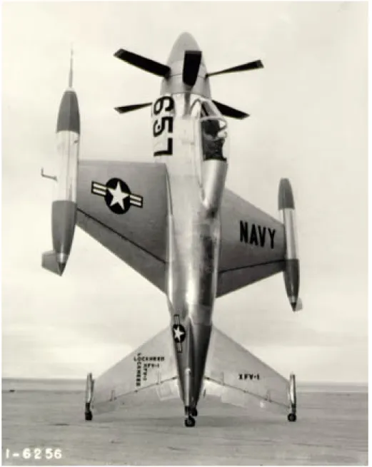
2.1.5 Tail Sitter
Tail sitter is one of the less common methods for achieving VTOL. As the name suggests the aircraft will be placed with its nose pointing up sitting on its tail, see figure9 in the appendix. The aircraft will usually have four landing gears placed on either the wings or the rudders at the rear of the aircraft. This makes taking-off and switching to horizontal flight simple but it also limits the control during vertical flight. Thus it is fitting for aircraft that don’t intend to spend time in vertical flight. Also landing requires some very specific maneuvers [12].
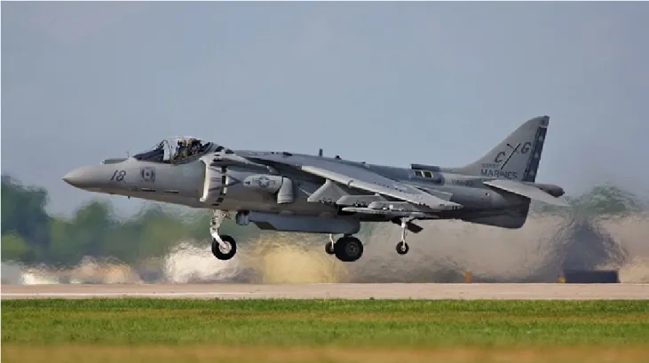
2.1.6 Vectored Thrust
Vectored thrust is the jet engine solution toVTOL. This method also relies on tilting the source of thrust but instead of tilting the whole engine only the nozzle rotates, see figure 10 in the appendix.This method has the normal advantages and drawbacks that jetplanes have. They are very fast but also fuel inefficient. They have a fast transition from vertical to horizontal flight but this is because the aircraft is essentially blasted upwards, this of course leads to poor control during vertical flight. Vectored thrust is not relevant for this thesis since theUAVwill be powered by electricity.
2.2
Exampel Aircraft
2.2.1 V22 Osprey
The V22 Osprey is one of the more popular and well knownVTOLcapable aircraft in use today, see figure11in the appendix. It sees extensive use in the US marine corps as a transport aircraft, it can reach altitudes of 3700 meters and has a maximum speed of 500 km/h. The Osprey is a tiltrotor aircraft and it has two main rotors at the end of each wing, this gives the aircraft excellent control during vertical flight and allows relatively fast transition from vertical to horizontal flight, only 12 seconds. The tiltrotor design causes the aircraft to loose some lift from having the rotors
placed above the wings. The engines are connected by drive shaft to a common gear box thus both propellers can be powered by a single engine, the aircraft can’t perform vertical flight with only one engine but a safe landing is possible. Should both engines fail however a safe landing is very difficult since the aircraft has poor autorotation capabilities. The aircraft is also very expensive since the two very large engines require a loot of fuel [13].
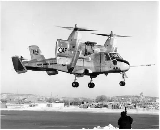
2.2.2 Canadair CL-84
The CL-84 is a tiltwing aircraft intended for military use, see figure12in the appendix, unfortu-nately it never entered production. Even though it was retired it has a promising tiltwing design. The maximum speed recorded during testing is 517 km/h and the maximum altitude was never properly tested but was calculated to be approximately 3000 meters. The aircraft uses two rotors that are fixed on the main wing place at the center of the aircraft. The design proved fast and controllable during horizontal flight and its vertical flight performance proved sufficient to land on a carrier. The tiltwing design also helped the transition time from vertical to horizontal flight being capable of entering horizontal flight in only 8 seconds [14].
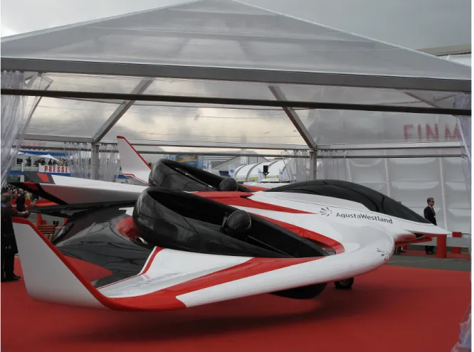
2.2.3 Project Zero
Project Zero is the name of a hybrid tiltrotor/fan-in-wing aircraft that is currently being tested, see figure13in the appendix. It uses electrical engines that draw power from an onboard battery, because of this the aircraft has very poor flight time although there are plans to extend the flight time by installing a small diesel engine. The aircraft uses a flying wing design and has two large propellers built in to the body. The propellers can be rotated to provide forward thrust for horizontal flight and also to improve control during vertical flight. Project Zero is still in the testing phase and there is a limited amount of information available, but it can hover and works as proof that a hybrid tiltrotor/fan-in-wing aircraft is possible [15].
2.2.4 Joby S2
Joby S2 is a new type of tiltrotor aircraft that is under development. The main idea behind this new concept is to use the tiltrotor method but instead only tilting the propellers. The aircraft uses 16 rotors placed on two sets of wings and when in vertical flight mode the propellers are pointing up, then as the aircraft switches to horizontal flight mode the propellers are folded down and finally as the aircraft enters horizontal flight the propellers stop and are folded in completely. Then four smaller propellers at the rear of each wing are started to maintain cruising sped. 2.2.5 Firefly 6
FireFLY 6 is a tiltrotorUAVthat uses an interesting design. The body is reminiscent of a flying wing and the rotors are attached to a rotating shafts, two placed at the front of the aircraft pointing to each side of the nose, and one at the rear pointing back. Each shaft has two electrical motors at the end one pointing up and one down each with a propeller attached to give upwards lift. This allows the aircraft to fly vertically like a tricopter but the shafts can be rotated so that the four front rotors provide forward thrust allowing the aircraft horizontal flight similar to an airplane. The rear shaft will also rotate and can then provide sideways thrust to increase the aircrafts maneuverability in horizontal flight.
2.2.6 LightningStrike
LightningStrike is an experimentalVTOL UAV that is in development, it uses a hybrid fan-in-wing/tiltwing designs that have large bulky wings that have chambers to house the propellers. The aircraft has two large main wings that are place above the body. It also has two smaller wings at the rear to help with stability and control. 18 propellers are placed on the main wing and 6 in the rear wing. The wings can be rotated and during vertical flight the are place in the side so that the propellers point down and as the aircraft transitions to horizontal flight the wings are rotated so the propellers can provide forward thrust.
2.2.7 Arcturus Jump 20
The Jump 20 is a fixed wing UAV that uses four rotors placed on a beam under the two wings to achieve vertical flight. During vertical flight the UAV acts like a quadrocopter, but during horizontal flight the wings also help by providing lift thus increasing the flight time. Since the rotors are fixed the aircraft actually has more in common with a quadrocopter than an airplane.
2.3
Motor and Propeller Calculations
A big part of the design process will be choosing motors and propellers, to do this there are some variables that must be accounted for, such as thrust, energy consumption and propeller efficiency. These and how they will affect the design decisions will be examined in more detail in the following sections.
2.3.1 Thrust
The single most important aspect of the motor and propeller, the thrust generated by the rotor must be great enough to overcome the weight of the aircraft, otherwise flight is impossible. The thrust generated by a propeller can described with equation1, [16].
T = (π/4) ∗ D2∗ ρ ∗ ν ∗ ∆ν (1)
• T is the thrust generated by the propeller and is measured in Newtons.
• ρ is the density of the medium wich the propeller will be displacing to generate thrust, in this case the medium is air. Thus ρ = 1.225kg/m3
• D is the diameter of the choosen propeller.
• ∆ν is the exit velocity of the air accelerated by the propeller and is measured in m/s • ν is the velocity of the air entering the propeller.
By using the equations on the functions of propeller thrust, [17], ν can be expressed as ν = ∆ν/2 thus equation1 can be rewritten as equation2
T = (π/8) ∗ D2∗ ρ ∗ (∆ν/2)2 (2)
Since ∆ν is har to calculate and must otherwise be measured physically we will substitute it using the following equation3.
P = (T ∗ ∆ν)/2→∆ν = 2P/T (3)
Thus equation2can be written as equation 4
T = [(π/2) ∗ D2∗ ρ ∗ P2)]1/3 (4)
P is the power transmitted by the motor to the propeller. P can be calculated using the following equation5.
P = P c ∗ rpmP f (5)
• P is measuerd in watts. • Pc is the propeller constant.
• rpm is the rotational speed of the propeller, rotations per minute. • Pf is the Power-factor.
Pf and Pc are constants that are specific for different propeller types and describe how the propeller behaves during flight, these can’t easely be calculated and are usually determaind through tests that are beyond the scope of this thesis. Thus the propeller constant has to be found through other means, the manufacturers seldom give this information but there are other sources where the propeller constant for different propellers can be found, these are mostly for smaller propellers however. For larger propellers there is very little information so another method will have to be used. For the purpose of this thesis the propeller constant and power factor has been combined in to one constant and the Power equation5has ben modified to the following.
P = k ∗ rpm3∗ D4∗ pitch (6)
• k is the new propeller and power factor constant, it is 5.41 ∗ 10−16
• D is the propeller diameter in inch
• rpm is the rotational speed of the propeller, rotations per minute. • pitch is the propeller pitch in inch
This equation is based on a similar equation for calculating the lift for propellers and motors for model airplanes, [18]. This equation gives a good estimate of the thrust power requirements of model propellers. This equation has then been modified to instead provide an estimate for propellers in the size required to lift theUAV. This equation has then been tested for the consid-ered propellers by comparing the calculated thrust provided by a particular propeller and motor combination to the listed thrust provided by the manufacturer.
Propeller constant test results.
These results are not exact but are close enough that the propellers performance can be esti-mated. However for future work it is recommended that the exact performance of the propellers is determined.
2.3.2 Energy
Newton’s first law can help determine the amount of force needed to lift the aircraft, it reads as follows F = m ∗ a. What this means for theUAVis that the weight of the aircraft multiplied by the gravitational constant determines the amount of thrust that must be produced to lift the aircraft. It also describes the action of the propellers, the amount of air accelerated by the propeller to provide the thrust. This would suggest that the amount of air is equally important to the speed of which the air is displaced. However the equation for kinetic energy suggests otherwise, the equation reads as follows E = (m ∗ V2)/2. Where E is the energy, m is the mass and V is the velocity. For the UAV this means that the energy needed to accelerate an amount of air to a certain speed requires a corresponding amount of energy. As can be seen from the equation the energy increases linearly with the mass but exponentially with the speed. Thus it is more energy efficient to accelerate a loot of air to a low speed compared to a small amount of air to a high speed. This means that a bigger propeller is more energy efficient.
2.3.3 Propeller Efficiency
Propeller efficiency is a term that describes how efficiently the propeller provides thrust, it is expressed in percent, thus telling how much of the theoretical thrust is actually provided [19]. The propeller efficiency is the result of the angle of the propeller and the advance ratio. The advance ratio is the ratio of the freestream air speed to the propeller tip speed [20]. This means that the difference in speed of the aircraft and the rotational speed of the propeller will give either a high or low advance ratio. The advance ratio can be calculated using the following equation7.
J = V a/nD (7)
• J is the advance ratio.
• n is the propellers rps (rotations per second). • D is the propeller diameter.
The propeller efficiency can then be found using this graph representing the generic propeller efficiency versus advance ratio, [19]. This will only give a rough estimation of the propeller efficiency at a certain speed but that is sufficient for this thesis.
2.3.4 Torque
To calculate how much torque is required to spin a propeller of a certain size the formula for steady mass flow can be used, [21], [22].
F in = A ∗ ρ ∗ v2= F out = A ∗ ρ ∗ v2 (8)
• Fin is the force of the incoming air on the propeller. • Fout is the force of the outgoing air.
• A is the area of the incoming flow and can be expressed as: A = c/3 ∗ dr. Where dr is the distance from the center of the propeller to a certain point of the propeller blade and c is the width of the blade, [23].
• ρ is the air density.
• v is the air velocity and can be expressed as v = ω ∗ r. Where ω is the rotational speed of the propeller and r is the radius.
To find the torque the drag and the lift from the propeller blade must be found, they can be expressed as follows:
dD = F in − F out ∗ cos(θ) (9)
dL = F out ∗ sin(θ) (10)
• θ is the angle of the propeller blade. • dD is the drag.
• dL is the lift.
Equation9can then be rewritten as:
dD = A ∗ ρ ∗ v2∗ (1 − cos(θ)) (11)
Rewrite A and v.
dD = c/3 ∗ ρ ∗ ω2∗ r3∗ (1 − cos(θ))dr (12)
Integrate by r.
D = dD = c/3 ∗ ρ ∗ ω2∗ (r4)/4 ∗ (1 − cos(θ)) = M (13)
This gives the moment in Nm or the torque required to turn the propeller, but since c and ω are difficult to Fd dL will be used to remove these.
dL = c/3 ∗ ρ ∗ ω2∗ r2∗ sin(θ)dr (14)
If the aircraft is hovering L will be equal to mg which is the total weight that the propellers need to lift.
mg = c/3 ∗ ρ ∗ ω2∗ (r3)/3 ∗ sin(θ) (16)
c ∗ ρ ∗ ω2∗ r3= (mg ∗ 9)/sin(θ) (17)
This can be substituted in equation13
M = (3 ∗ mg)/4 ∗ ((1 − cos(θ))/sin(θ)) ∗ r (18)
2.4
Batteries
The batteries put the biggest limitations on the UAV, to carry the UAV and the cargo fairly powerful motors are required. To power these motors and allow for sufficient flight time a large number of batteries are needed, this increases weight and thus more power is needed to lift the
UAVand this decreases flight time. This creates a vicious circle where more batteries are needed which increases the weight which increases power demand which in turn increases the demand for more batteries. This fuel weight problem is common for most aircrafts and a balance has to be maintained. This balance is harder to maintain on an aircraft that is completely powered by electricity, since the energy density of gasoline and diesel is vastly superior to even the best batteries. Gasoline has an energy density of approximately 12700 Wh/kg, [24], while the the leading lithium-ion batteries have an energy density of around 300 Wh/kg, [25]. This means that even with the higher efficiency of electric motors, [26], more of the aircrafts weight will have to consist of fuel, or in this case, batteries.
2.5
Increasing Range
To increase the range of theUAVtwo main ideas where considered, the first was to make theUAV
capable of gliding by transforming it into a sailplane. The second was to put solarpanels on the
UAV. This thesis chose to focus on the sailplane ide because of the relatively smal surface area
UAVwhich limits the amount of solar panels that can be mounted as well as the extra weight the solar panels would add.
2.5.1 Sailplanes
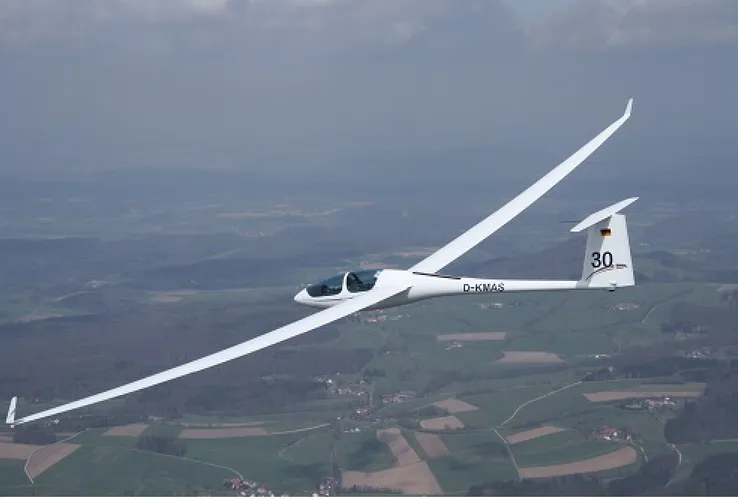
The idea of sailplanes existed even before the actual airplanes, actual gliders can be traced back to the 1800s. After the first world war sailplanes and gliders where used for mainly sporting purposes but during the second world war they where adopted for military use. A sailplane is an unpowered aircraft with large wings that give a loot of lift, to increase the lift to drag ratio the wings are often very long and thin, [27],[28]. To achieve flight all sailplanes and gliders require some form of aid to reach an altitude from where they can start gliding. There are several ways to do this, from just a person carrying the glider to the top of a hill or another airplane towing the sailplane to the target altitude. To further increase the range of sailplanes the pilot will ridethermals to higher altitudes. Modern sailplanes are very aerodynamic and can glide very long distances at relatively high speeds, se picture14
3
Method
This section of the thesis will take a closer look at the actual process of choosing the components and designing the motor system. It is separated in to three parts, the first part section3.1 will look at the general thought process and requirements that are placed on the motor system and the
UAV. Section3.2will go in to more detail on the process of placing the wings and rotors on the body as well as the process of choosing motors and propellers. Lastly section3.3will look at the process of choosing the batteries and other electronic components.
3.1
General
The design of the motor system can be divided into two parts, the first is the mechanics part the second is the electronics part. The mechanics part include the general design of the wings, this needs to be done since the placement of the motors will be very important to the motor system. It is also arguable that the choice of motor and propeller is part of the mechanics since they will be chosen based mainly based on the characteristics of the mechanical design. For instance the weight and size of the UAV will affect the kind of motor and propeller that can be used, and the placement of the rotors will very much affect the propellers since the have to fit and not risk hitting anything. But the choice of motor is also partially electric since all of the electronic components will have to be chosen based on the motors. All of the components must be able to handle the strain that the motor will put on them and the battery must be able to supply the required power. Thus there will need to be a specific order in which the different parts are done. First the mechanical design will need to be established, second the placement of the rotors on the wings and body after that the motor can be chosen followed by the battery and electronics.
3.2
Mechanics
3.2.1 Design
Because of the poor energy density of batteries the actual powered flight time of the UAV will be very short. This means that other methods have to be taken to achieve the desired range of the UAV. There are two main methods that have been considered, the first is to extend the power supply by the way of solarpanels. The second is to give the UAV large wings that will allow it to act like a sailplane [29], the method that has been given most thought in this thesis is the sailplane method. TheUAVwill then use the rotors to ascend to a predetermined altitude and then proceed to glide from that point and turning off the motors to save power. Then when theUAV reaches a low altitude the motors will be powered on once more to ascend to a higher altitude. This pattern will continue until the destination has been reached. Since the actual design of theUAVis not part of this thesis only the general placement of the wings and the rotors will be considered. However to make an informed decision about the wings and motors the weight of the body needs to be estimated. The target weight of the entireUAV, including body, wings, motor, propeller, electronics and cargo will be 495 kilograms. The 495 kilogram limit comes from the Swedish department of transportation [30], here it is stated that an amphibious aircraft can weigh no more than 495 kilograms if it wants to be classified as an ultralight aircraft, this classification is desirable since there are fewer restrictions placed on ultralight aircrafts.
3.2.2 Body
For this thesis the body will be considered as a simple box that has enough room to house the electronics and the cargo. The material used for the weight estimation will be aluminum and carbon fiber. The specific type of aluminum used in this thesis is aluminum 2024-T3 which is an aluminum type common in aircrafts, the carbon fiber will be simple 1.5 mm thick carbon fiber sheets. Several aluminum rods will be used as a skeleton for the box and the carbon fiber plates will be used as cover, the dimensions of the body will be 2600 mm long, 1200 mm wide and 410 mm high, se picture15,16in the appendix.
3.2.3 Wings
The mechanics in this thesis will include a simple model of the wings, since the general design of the wings need to be known for the placement of the motors. The wings will need to be large to provide enough lift for theUAV to be able to act as a sailplane. The surface are of the wings is what determines the lift, [31], [32], however the length and width of the wings will determine the lift to drag ratio, [28]. A high lift to drag ratio means that the aircraft will have good gliding capabilities, and the width of the wings is the biggest contributer to drag caused by the wings. Thus ling thin wings is the aim for thisUAV, the wings can’t be to thin however since they must be able to support their own weight. An estimate of the wing size will be calculated, to determine the lift provided by a set of wings the following equation can be used.
L = ((ρ ∗ V2)/2) ∗ A ∗ Cl (19)
• L is the lift in pounds.
• ρ is the air density at the relevant altitude in slugs/f t3, at 1000 meters this is 0.0022.
• V is the velocity of the aircraft in feet per second. • A is the surface are of the wings in square feet.
Cl is the lift coefficient based on the shape and angle of the wing. Usually the lift coefficient is found using a wind tunnel but for these calculations an approximation can be found using this graph, [33]. The angle of the wings will be between 6 and 8 degrees so Cl will be 0,8. The wings will need to lift approximately 500 kilograms, or 1102 pounds. For the velocity 140 km/h, or 127 feet/s, will be used. Modern sailplanes can often reach speeds of above 200 km/h, thisUAVis not expected to perform that well, [34],[35]. The total wing area will then be 7,1 square meters.
To increase the stability of the aircraft the wings will be placed above the mass center of the
UAVand furthermore the wings must be placed so that the rotors and the wings don’t interfere with eachother. The solution was to place the wings on the roof of the aircraft so that the body will be hanging from the wings when gliding, se picture17in the appendix.
3.2.4 Motor and Propeller
The motor and propeller is one of the biggest parts of this thesis. The choice of these components will have a big inpact on the performance and capabilities of theUAV. The first step is to figure out where the rotors will be placed and how many will be used. The simplest solution is to use an already tried and tested method for achieving stable multirotor flight, in this case a simple quad rotor setup will give the desired stability and control without increasing the complexity of the motor system. Because of the estimated shape of the body the easiest placement for the rotors will be two attached to the sides at both the front and back of the aircraft. The rotors should be placed so that the propellers are above the center of mass to increase stability during vertical flight.
With an estimated weight of 495 kilograms the motor and propeller need to be able to provide 4851 newtons of thrust to lift theUAV. However to give theUAVreasonable control during vertical flight and to allow the UAV to reach the required altitude additional thrust is required, a good benchmark provided by other transport aircraft is approximately 1.6 times the thrust required to lift the aircraft, so 7761 newton, this will then be split between the four rotors so each should be able to provide 1940 newton each. As can be seen in equation2 the thrust provided by a rotor is mainly dependent on the diameter of the propeller and the power transferred from the motor to the propeller and as can be seen in equation 4 the power depends on the rpm of the motor, the diameter of the propeller and the propeller pitch. Also the torque required to spin a propeller of a certain size can be found using equation 18. With this information the process of choosing propeller and motor can begin, first several propellers of different sizes will be picked and the power, rpm and torque required by the motor to reach the target thrust will be calculated.
With this information a motor could be chosen that could fulfill these requirements.
After testing the combination that was chosen was the 68 inch propeller and the EMRAX 208 motor. The propeller was chosen since larger propellers are more energy efficient, but to large and
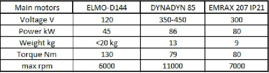
Figure 1: Performance of different propellers depending on diameter and pitch
Figure 2: Table showing the technical data for the different motors
it will require stronger larger motors to handel the propeller and attaching larger propellers to the body will be difficult since the wings and the body will block the thrust from the propeller. It is possible that larger propellers can be used and this will increase efficiency, this however will require careful design of both the body and wings and that is beyond the scope of this thesis. While the general size and pitch of the propeller can be found from several different manufacturers, the specific propeller that this thesis will use is the powerfin F model blade, with an apex hub. These are lightweight high performance propellers with hubs that allow for variable pitch should this need to be adjusted.
When choosing motors there are several aspects that have to be looked at. The first is if the motor has a higher enough torque to spin the propeller, the second is if the motor has a high enough rpm to provide the thrust needed to lift theUAV. After these to points have been fulfilled the power, voltage and weight can be considered. Lower voltage and power will mean that they drain the batteries slower, these are however tide to the rpm and torque. Lower weight is always good since it will also mean that the motor has to work less to lift its own weight. Of the motors that where considered only the DYNADYN and the EMRAX fulfilled the requirements and of these the EMRAX was chosen because of its lower weight.
Finally the rotors must be attached to the body somehow, this is not possible to do since the attachment method will be based on the design of the body and that is not a part of this thesis, a suggestion can still be made however. The method considered in this thesis was based on the method that was used in the smallUAVproject to attach the motors, [2]. Which is to use a large tube made of a sturdy and lightweight material as a base. The motor will then be fitted with a mount that can be attached to the tube with the help of clamps. Since this is only a suggestion carbonfiber will be the considered material for the tube. To place the rotors at the desired position the carbon fiber tubes will have to be 2800 mm long, on placed at the fron of theUAV and the other at the back, se picture18in the appendix.
The tubes would have to be able to handle a force of 1941 newton applied to each end of the tube. The tubes that where considered for this thesis where M46J high modulus carbon fiber tubes with a diameter of 44.45 mm and a wall thickness of 1.57 mm. These tubes can be attached to the body using attachment brackets, a solid model was made of these so that tests could performed
19in the appendix. AFEMsimulation was made to test the tubes, here tubes are fixed with two attachment brackets and a force of 1941 newton is applied to each end, se pictures23, 24 in the
appendix.
To attach the motors to the tubes both clamps and a mount are needed. The EMRAX 208 has a custom carrier that could be used as a mount, [36]. To attach this mount to the tube custom clamps would have to be made. The carrier is made out of stainless steel and for simplicity the clamps could be made out of the same material, se picture20 in the appendix. To test this mounting solution aFEMsimulation was made, here the clamps are fixed where they would be attached to the tube. The force is applied to the mounting holes on the top part of the carrier, se picture25in the appendix.
3.3
Electronics
The electrical components that will be part of this thesis are the batteries, ESC and a way to distribute the power from the batteries to theESC. Furthermore if the lacks a low cut of voltage circuit this should also be added.
3.3.1 Power Distribution
Because of the high current and voltage needed to power the motors a conventionalPDBcould not be fit on theUAV. The only availablePDB’s that can handle such a high load are industrialPDB’s. However, these types ofPDB’s often weigh hundreds of kilograms and are meant to be stationary. This is just not feasible to mount on theUAV. Thus another method of distributing power was considered. Instead of having a single powersource power all of the components, theUAV’s power system will need to be separated in two parts, the motor system and other electronics, this thesis will only consider the motor system part. Because this system will only need to provide power to four motors a simple method of creating four separate groups of batteries that will each power one motor was decided on. Each battery group will then provide power to oneESC and thisESC in turn will control the motor, picture27,28in the appendix.
3.3.2 Battery
The battery needs to be able to supply the correct voltage and current, because of the high power requirements of the motors used in theUAV several batteries will have to be connected in both series and parallel to supply the required voltage and current. Several different batteries and battery cells where considered for theUAV.
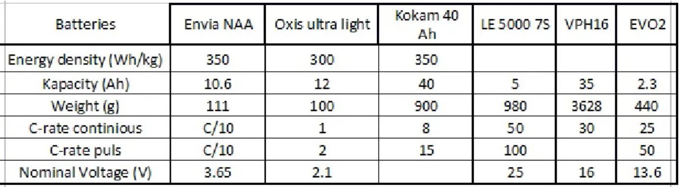
Figure 3: Table showing the different batteries
When choosing the battery there are several different aspects that need to be considered. The ones that where given the most consideration where capacity, weight, C-rate and nominal voltage. The motors used for this version will be four EMRAX 208,2. With a voltage of 300 volts and 80 kW of power. The continuous current load is 160 ampere and the burst current load is 320. With four motors the battery will need to provide 1280 ampere and 300 volts. To figure out the best battery for theUAVthe number of each battery needed to power the motors must be calculated. Oxis: If the battery Oxis ultra-light would be used for the UAV the following number of cells would have to be used. The batter has a C-rate of 1, this means that it can provide 12 ampere for
one hour. Thus to meet the EMRAX required current draw of 160 ampere, 14 Oxis cells would have to be connected in parallel to power one motor, to power all four 56 cells would be needed. Furthermore the EMRAX needs a voltage supply of 300 volts, the battery cells have a nominal voltage of 2.1 volts and thus 143 Oxis cells would have to be connected in series to supply this voltage. So 56 parallel sets of 143 serial cells, that is 8008 battery cells, would be needed to power one of the motors for one hour. The total weight is 800 kilograms, this is not viable. LE 5000 7S: With a capacity of 5 Ah and a C-rate of 50 this battery will be able to supply 250 ampere, but it will discharge itself in 1.2 minutes. To provide the 640 ampere needed to power all four of the motors only three parallel batteries would be needed. The battery can supply a voltage of 25 and thus only 12 batteries would be connected in series. Thus 36 batteries would be needed in total to power the motor, the total weight of these batteries would be 35 kilograms. VPH16: Capacity 35 Ah and a C-rate of 30 means that this battery supplies 1050 ampere and discharges itself in 2 minutes. Only one is needed to supply the current needed to power the motors at cruise speed but two will be needed in parallel if the motors run at maximum speed, but then the batteries will discharge slower. To supply 300 volts 19 batteries will be needed in series. 38 batteries would be needed in total and this would weigh 136 kilograms. EVO2: Capacity 2.3 Ah and a C-rate of 25 will provide 57.5 ampere and will discharge itself in 2.4 minutes. 12 batteries would be needed in parallel to provide the current. To provide 300 volts 23 batteries need to be connected in series. In total 276 batteries are needed, total weight is 121 kilograms.
Out of these the LE 5000 7S was chosen since they are low weight but still have a high c-rate and thus can power the motors without needing to many batteries in parallel. The batteries will be organized in four separate groups as was decided in the power distribution section. To provide the correct voltage 12 batteries will be connected in series. One motor will have acontinus draw of approximately 160 ampere at cruising speed, this means that one line can power this motor for 1.875 minutes and each further line will increase the flight time by this much, one such line will weigh 11.76 kilograms. Each group will need an equal number of lines to allow for the motors to operate in sync, so each group is allowed 50 kilograms of batteries, this will give each group four lines of 12 batteries weighing at a total of 188 kilograms and with a powered flight time of 7.5 minutes.
Now that the type and number of batteries have been chosen a way to store them has to be decided. The method that was decided on was to take a block of high density polyethylene or similar plastic material. Several chambers will be cut in to it that can house the batteries. This is a simple solution that separates the batteries, offers some protection and can make changing the batteries easier since this block can be removed and the batteries can then be changed outside of the aircraft. Each of the battery groups will need a separate block, each block will be 325 mm wide 869 mm long and 107 mm high. There will be two rows of 12 chambers on each side of the block to house all the batteries for that group, se picture21.
3.3.3 Electronic Speed Control
Different electrical motors use different ESC’s, so the first step is to make sure that the chosen
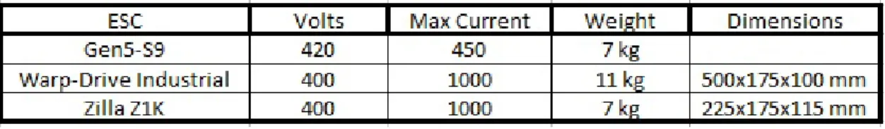
ESC is made for brushless DC motors. The second step is to check if the ESC can handle the required voltage and current. Each motor will need a separateESC so each ESCwill need to be able to handel 300 volts and 320 ampere. That large of a load will require industrial sizedESC’s. There where a few differentESC that where considered.
Figure 4: Table showing the features of the ESC’s
Out of these the Zilla Z1k and the sevcon Gen5-s9 where given the most thought. Both are customizable and could be used to control several different kinds of motors, the Sevcon gen 5
however seemed the most reliable and and can be directly programmed and controlled using a computer while the Zilla Z1k needs its own controller.
3.3.4 Cables
The final part of the electronics will be the cables. The biggest load that will be put on the system is when the motors run at maximum speed, the highest voltage and current draw from the motor is 300 volts and 320 ampere. So all the cables connecting the motors to the batteries must be large enough to handel this load, however the size of the cable will also be affected by the distance and the material. The material will be cooper since it is the most common and cheapest option. The distance will depend on where the cable will be run, first the cable will run form the batteries to theESC and then from theESCto the motor. From the batteries to theESCthe distance is not expected to be longer than 0.5 meters and from theESC to the motor the distance is expected to be longer than 1.5 meters. When the cables are large enough to handle a current of 320 ampere this difference in distance is not large enough to affect the cable size so the same cable can be used. The cable will have aMCMof 350, this translates to a cable with a core diameter of 15 mm. The total length of the cables will be 8 meters.
4
Results
This section is dedicated to the results of the thesis. Section 4.1 will describe the final design, section4.2will list the final components and section4.3will evaluate the performance of theUAV.
4.1
Design
This thesis will detail some of the limitations and requirements that will be put on the design of the UAVbecause of the motor system and the performance requirements. The body must be large enough to house the components as well as the cargo. The cargo consists of three naiads, the components are the batteries, theESCand other electronic components that will be added for the flight system and navigation. Thus the body will be 2600 mm long, 800 mm wide and 410 mm high, se picture16in the appendix.
The wings will have to be large enough to carry the aircraft during gliding flight. The target weight of the aircraft is 495 kilograms and to carry this weight the wings will have to have an area of 7.1 square meters. To reduce drag the wings should be as thin as possible, the exact wing design will not be detailed in this thesis. The wings should be placed on top of that aircraft to increase stability and to reduce interference with and from the propellers, se picture17in the appendix.
The rotors should be placed at the front and back of the aircraft, they should also be placed above the center of mass but below the wings. They will also have to extrude from the body enough to allow for the propellers to spin. The suggested solution is to mount the rotors on a tube that is attached to the body at the correct position, se picture18in the appendix.
To give a sense of how the body would look when complete a simple model has been made with the chosen components,22in the appendix.
4.2
Components
This section will list the chosen components, both the mechanical and the electronic components. 4.2.1 Propeller
The propeller will have a diameter of 68 inch and a pitch of 28 inch. Any propeller of this size will work, there will be some performance differences since even propellers of the same size will have a slightly different propeller constant but not enough to completely invalidate the propeller. The chosen propeller was a two bladed powerfin f-blade mounted on an apex hub. This is a high performance ultralight propeller that was chosen for its low weight.
4.2.2 Motor
The motor needs to be able to provide the necessary thrust to lift theUAV. The motor requirements will depend on the chosen propeller, se table1, the motor needs enough power, rpm and torque to power the propeller and provide the needed thrust. The motor and propeller should proved about 1.6 times the needed thrust. The chosen motor is the EMRAX 208, it was chosen because of the low weight, se table2.
4.2.3 Batteries
The batteries will have to provide enough voltage and current to power the motor, the motors power requirements can be found here,2. The chosen battery should have a good power to weight ratio while still having a high enough C-rate to power the motor, se table3. The chosen battery is the LE 5000 7S, to meet the motor requirements several batteries will have to be connected in both series and parallel. To meet the voltage requirements 12 batteries will have to be connected in series. To meet the average current requirements only one battery line is needed in parallel, however to meet the peak current two lines are needed.
4.2.4 ESC
First theESCmust also be able to control a brushless threephase electric motor, second theESC
must be able to handle the voltage and current required to power the motor, se table2. The chosen
ESCis the Gen5-S9, se table4. It was chosen for the low weight and it is programmable so it can handle several different kinds of motors which might prove useful should different motors need to be used in the future.
4.3
Performance
This section will detail the different aspects and performance of the UAV based on the design decisions and component choices.
4.3.1 Weight
The actual weight of theUAVis not possible to calculate since the body and wings have not been designed, however an estimate can still be made.
The size of the body has already been detailed in section4.1, for the purpose of this thesis the material used for the body will be aluminum rods for the skeleton. The aluminum rods used for the skeleton will be 20 mm wide and 8 mm thick, these are thick enough to carry the weight of the cargo and batteries, se picture26in the appendix. The total length of the aluminum rods will have to be 24900 mm, this will in total weigh 13 kilograms. For the cover carbon fiber plates will be used, these plates will be 1.5 mm thick and to cover the body completely 9.36 square meter of carbon fiber will be needed, this would weigh approximately 20 kilograms. So the total weight of the body is 33 kilograms, this will be increased to 43 kilograms to account for the uncertainty of not having an actual body design.
The size of the wings was also detailed in section4.1. For simplicity the wings will also use aluminum rods for the skeleton, a 15 mm wide and 6 mm thick aluminum rod will be used as a core. This would be approximately 15800 mm long and weigh 4 kilograms. For cover the same carbon fiber will be used but the plates will only be 1 mm thick, the area of the wings need to be 7.1 square meters and to cover both sides 14.2 square meters of carbon fiber will be used. This will weigh approximately 23 kilograms. The total weight of the wings will be 27 kilograms, this will be increased to 37 kilograms to account for uncertainty.
The cargo will be three naiads, these weigh approximately 33 kilograms each so the cargo will weigh 99 kilograms.
The weight of the batteries was already calculated in section 3.3.2 and its 188 kilograms. The weight of the battery holders still needs to be determined, the measurements of each holder is 325x869x107 mm with 48 160x67x45 mm holes cut in to it. This gives each holder a total volume of 7064275mm3, the holders are made of high density polyethylene which has a density of 0.944g/cm3. This means that the total weight of the four holders is 26 kilograms. The total weight of the batteries plus the holders is 214 kilograms.
The propeller consists of two Powerfin F model blades mounted on an apex hub, this configu-ration weighs 2.95 kilograms, so the total weight of the propellers is 11.8 kilograms. The EMRAX 208,4.2.2, weighs 9 kilograms each so all four motors will weigh 36 kilograms. The chosen ESC,
4.2.4, weighs 7 kilograms each so all four will weigh 28 kilograms. Finally the cables connecting the batteries,ESCand motors,3.3.4. The cables will be 350 MCM and a total length of 8 meters, this would weigh approximately 13.8 kilograms.
The combined weight of the chosen components, the estimated body and wings as well as the cargo is 482.6 kilograms.
4.3.2 Range
The indendet flight pattern of theUAV will be to use the motors to reach a target altitude and then turn the motors off and glide using the large wings, then when theUAVreaches a minimum altitude the motors will be started again to start the cycle over. Thus the operational range of the
UAVwill depend on two things, the range of each glide step and the number of altitude changes that the motors can perform.
The batteries can power the motors for 7.5 minutes as detailed in section3.3.2, thus to calculate how many altitude changes can be performed the climbing rate will have to be calculated. The target altitude will be 1000 meters since that is the air density that both the propeller and wings have ben dimensioned for. The theoretical speed at which theUAVcan travel using the motors can be calculated using the following equation,20.
v = (2 ∗ (T − mg)/(ρ ∗ D ∗ A))(0.5) (20)
• T is the thrust which will be 7761 newton. • mg is the mass times gravity which is 4855. • ρ is the air density which is 1,225.
• D is the drag coefficient.
• A is the effective area of theUAV which will be the top of the body plus the wings, this is 9, 18m2.
This gives a climbing rate of 20 m/s or 72 km/h, this means that it would take the UVA 50 seconds to reach an altitude of 1000 meters, this does not account for soft start, realignment, interference form wind and other factors so to compensate this time will be doubled to 100 seconds. Next the range of each glide needs to be calculated, when an aircraft glides it will lose altitude depending on its glide ratio, this ratio depends on the angle of the flight path. The distance of one glide can be calculated using the following equation21
d = h/tan(a) (21)
• d ist the distance in meters. • h is the altitude in meters. • a is the angle of the flight path.
The altitude is already known, 1000 meters. However the Swedish department of transportation has put in regulations for ultralight aircrafts traveling over populated areas, the minimum altitude that is allowed is 300 meters so only 700 meters will be usable when traveling over city’s and other population centers, [37]. The angle will need to be minimized and can be described in the following way.
L = mg ∗ cos(a) (22)
D = mg ∗ sin(a) (23)
tan(a) = D/L (24)
So the angel ’a’ can be described using the drag and lift and these are defined in section3.2.3. Using this definition the angle can be described as.
tan(a) = Cd/Cl (25)
Which results in a = 7, 9 degrees. The distance can now be calculated and it is 5044 meters or approximately 5 kilometers with one altitude change. If it takes theUAV100 seconds to reach 1000 meters and the total powered flight time of theUAV is 7,5 minutes. This means that the
UAVwill be able to make a total of 4,5 climbes to 1000 meters, this gives theUAVa range of 22,5 kilometers, however the effective range will be halved since theUAVwill need to be able to make the return trip under its own power so 11,25 kilometers.
5
Future Work
Since this thesis is a part of a bigger project the future work is already laid out to an extent, however the future work that is specifically related to this thesis will be discussed. Due to the simplified design of both the wings and the body several parts of this thesis had to be estimated. Future work can be to make an actual design for the body and the wings, if this is done then the actual air resistance of the UAV can be found and more exact calculations can be made. This should also include choosing the material and calculating the exact weight. Future work could also include incorporating the flight controller and other supporting electronics such as GPS and gyroscope on to the UAV. Since the power distribution system developed in this thesis is very simple and will only power the motors a separate power system will have to be developed to power the other electronic components that will be needed to make theUAV operate. Another possibility for future work is to further develop the flight system to be able to detect and use thermals during flight, this is the main method that sailplane pilots use to extend the range of their flight,thermals. Making theUAVable to detect and use thermals could greatly extend the range as well as reduce the power requirements. Finally because of the time constraints only the sailplane method of increasing the UAV’s effective range was investigated, an important future work will be to investigate the possibility of combinging the method with other methods such as solar panels, this method appere to be more viabel if combined with the large wings to add more surface area to mount solar panels on.
6
Conclusion
The goal of this thesis was to determine the viability of a fully electric UAV capable of VTOL
flight. The results show that this is definitely possible, the motorsystem designed in this thesis fulfill all of the requirements but to achieve the desired range several steps had to be taken that will limit the flight capabilities of theUAV. The main limiting factor of a fully electronic system are the batteries, the average energy density of a lithium battery is 500 Wh/kg while gasoline has an energy density of 12,889 Wh/kg, [24]. Even with the high efficiency of electric motors the total weight of batteries needed to power one electric motor is far greater than the petroleum needed to power an equivalent combustion engine. Because of this low energy density the powered flight time of any fully electric aircraft will be severely limited and thus most existing methods forVTOL
flight was not viable for this UAV. Another method was developed that relies on several large electric motors to give theUAV VTOLcapabilities while the horizontal flight relies on large wings that allow theUAVto glide long distances. This dramatically increases the range of while limiting the overall maneuverability, this also puts large limitations on the design. The large wings might also cause theUAVto be unable to fly during harsh weather.
7
Acknowledgments
I would like to thank my supervisor Mirko Senkovski, lecturer at IDT, who was a big help during the design process. His help with determining the validity of the different designs was invaluable and made the design process much smoother.
Additionally I would like to thank my supervisor Jacob Brynolf, senior lecturer at IDT, who’s help with the difficult math and physics calculations was a tremendous help. Without his help some of the more advanced calculations would have made this thesis much more difficult.
I would also like to thank my examiner Mikael Ekstr¨om, associate professor at IDT. He helped me start this thesis and also helped me finish it.
Finally, to my family and friends who supported me throughout this thesis I would like to say thank you.
References
[1] MDH, “Mdh-roboten naiad ska s¨oka av ¨ostersj¨on efter farliga objekt,” 2013. [2] J. P. H. J. G. J. R. A. E. L. H. D. S. R. K. A., “Autonomous uav rostbiff,” 2017. [3] K. J. D. J. A. T. J. E. L. L., “Project in advanced system and robotics,” 2016.
[4] G.L.Ghiringhelli, P.Masarati, and P.Mantegazza, “Multi-body analysis of a tiltrotor configu-ration,” p. 25, 2000.
[5] C. Acree, H. Yeo, and J. D. Sinsay, “Performance optimization of the nasa large civil tiltrotor,” p. 15.
[6] J. R. Chambers and S. B. Grafton, “Static and dynamic longitudinal stability derivatives of a powered 1/9-scale model of a tilt-wing v/stol transport,” p. 51, 1966.
[7] K. Muraoka, Noriaki, Okada, D. Kubo, and M. Sato, “Transition flight of a quad tiltwing vtol uav,” p. 10, 2012.
[8] J. B. Wheatly, “The aerodynamic analysis of the gyroplane,” p. 30, 1934.
[9] Y. I. Somov and O. Y. Polyntsev, “Nonlinear dynamics and robust control of a gyroplance rotor,” p. 6, 2005.
[10] J. V. Kirk, B. K. Hodder, and L. P. Hall, “Large-scale wind-tunnel investigation of a v/stol transport model with wing-mounted lift fans and fusulage-mounted lift-cruise engines for propulsion,” p. 89, 1967.
[11] N. Thouault, V. Breitsamter, N. Adams, C. Gologan, and J. Seifert, “Experimental investi-gation of the aerodynamic characteristics of generic fan-in-wing configurations,” p. 12, 2009. [12] T. Matsumoto, K. Kita, R. Suzuki, A. Oosedo, K. Go, Y. Hoshino, A. Konno, and
M. Uchiyama, “A hovering control strategy for a tail-sitter vtol uav that increases stabil-ity against large disturbance,” p. 6, 2010.
[13] C. Bolkcom, “V-22 osprey tilt-rotor aircraft,” p. 24, 2004.
[14] L. W. J. and J. Nieusma, “An investigation of two-propeller tilt wing v/stol aircraft flight characteristics,” p. 89, 1993.
[15] S. Herbst, G. Wortmann, and M. Hornung, “Conceptual design studies of vertical takeoff and ladning remotely piloted aircraft systems for hybrid missions,” p. 14, 2015.
[16] M. Hepperle, “How a propeller works,” 1996.
[17] G. R. Center, “The beginner’s guide to aeronautics: Propeller thrust.” [18] S. Vorkoetter, “Propeller basics,” 2002.
[19] A. David F. Rogers, PhD, “Propeller efficiency rule of thumb,” p. 5, 2010.
[20] F. D. Harris, “Rotor performance at high advance ratio; theory versus test,” p. 521, 2008. [21] H. Okudo, “Steady mass flow,” p. 2.
[22] J. Meriam and K. L.G., “Engineering mechanics, dynamics,” 2001. [23] A. D.J. and S. K., “Glauert blade element theory.”
[24] A. Golnik, “Energy density of gasoline,” 2003. [25] O. Energy, “Ultra light lithium sulfur pouch cell.” [26] Siemens, “Abc of motors,” 2009.
[27] R. Lancaster, “Principles of glider flight,” 2007. [28] N. Hall, “Lift to drag ratio,” 2015.
[29] I. Kroo, “Nonplanar wing concepts for increased aircraft efficiency,” 2005. [30] K. Nilsson, “Transportstyrelsen forfattningssamling,” 2013.
[31] G. R. Center, “The lift equation,” 2015. [32] C. Hodanbosi, “Lift formula,” 2014.
[33] Auld and Srinivas, “Aerodynamics for students lift and lift coefficient,” 2016. [34] U. S. S. Teams, “Sailplanes and gliders,” 2004.
[35] M. A. Lundin, “Optimal soaring: What is the best speed to fly,” 2011.
[36] “Users manual for advanced axial flux synchronous motors and generators,” 2017. [37] Transportstyrelsen, “Transportstyrelsens forfattningssamling.”
A
Appendix
A.1
VTOL Methods
Figure 5: Tiltrotor aircraft
Figure 7: Gyroplane
Figure 10: Vectored thrust jump jet
A.2
Example Aircraft
Figure 14: Modern Sailplane
Figure 16: UAV Body
Figure 18: UAV Body with tubes to hold the motors
Figure 20: Clamps to mount the motor on the tube
Figure 22: Complete UAV
Figure 23: FEM test on carbon tube that will hold the motors, force applied uppwards