1
Concrete pavement Falkenberg, Sweden – a 20 year review
Ellen Dolk1, Johan Silfwerbrand2, Sigurdur Erlingsson3Abstract
The majority of the road network in Sweden consists of flexible pavements. Only a small fraction is rigid pavements and the most recent concrete structure was built ten years ago. This creates a problem as the national experience and knowledge in terms of design and maintenance of rigid pavements is not maintained. It is therefore important to gather and adequately document the performance of existing concrete structures. One such structure is along the motorway E6 close to Falkenberg on the southwest coast of Sweden built in 1993-1996. The structure is a 28 km long Jointed Plain Concrete Pavement (JPCP) resting on a cement-treated base. The climate in the area consists of a typical coastal climate with high precipitation and short, relatively warm summers and relatively cold winters with a high number of zero degree changes. Studded tire wear, normally contributing to a large extent to the total rut on the Swedish road network, is only 5 mm after these 20 years. However, the structure is suffering from longitudinal cracking along the outer wheel track that is thought to have been caused by the combined effects of erosion within the cement-treated base, resulting in cavities under the concrete slabs and the fact that the dowel bars are placed too low and thus reducing the load transfer mechanism between the slabs and acting as crack inducers.
Introduction
Several concrete roads were built in Sweden in the middle of the 20th century, but the life span of these was shorter than projected and the roads were rather soon repaved with asphalt. An improved construction was introduced during the 1970’s and the two stretches of road that were built in southern Sweden then both had a life span of over 30 years. In the 1990’s there were further improvements to the design of a couple of concrete pavement stretches, and these together with one road built 2006 make up today’s Swedish concrete road network of 68 km.
Research Significance
Sweden has few concrete roads with many years between constructions, making experience hard to come by. With goals such as building for a sustainable future coupled with progress toward heavier transport vehicles on roads in Sweden there is a need to have proper
information about the pros and cons of concrete pavement in a Scandinavian climate. This paper aims at extracting knowledge and experience from one of Sweden’s oldest concrete roads in use to learn do’s and don’ts for the future.
Case Study: Falkenberg
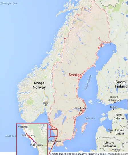
The concrete road in Falkenberg is a four lane motorway with a total width of 9 meters and built in two stages. The first stage is to the north (shown in red in Figure 1) between Långås and Heberg; it is 15 km long and built in 1993 as a 220 mm Jointed Plain Concrete Pavement with a maximum aggregate size of 22 mm and a spacing between the joints of 5 meters (see Figure 2) (Hultqvist & Carlsson, 1995). The northern part of stage one has a 150 mm base of
1 Research Engineer, MSc, VTI, Swedish National Road and Transport Research Institute, SE-581 95 Linköping, Sweden, Tel +46 13 20 42 46, e-mail: ellen.dolk@vti.se.
2 Professor & Department Head, KTH Royal Institute of Technology, Dept. of Civil & Architectural Engineering, Brinellvägen 23,
SE-100 44 Stockholm, Sweden, Tel +46 8 790 8033, e-mail: jsilfwer@kth.se.
3 Professor Pavement Technology, VTI, Swedish National Road and Transport Research Institute, SE-581 95 Linköping, Sweden, Tel +46
2
lean concrete while the southern part has a 100 mm asphalt base due to the greater risk of settlement close to a river. Both stages were built with concrete class K60, meaning a
corresponding compressive strength of 60 MPa and with a very wear resistant aggregate in the top 50-60 mm. This means that the concrete pavement was cast in two layers with two slip-form pavers.
Figure 1 – Map showing Falkenberg E6 concrete road stretch, stage one in red and stage two in purple.
Stage two is a 200 mm thick concrete pavement on a cement-treated base, 13 km long with a variation of designs but mainly jointed plain concrete with dowels, a joint spacing of 5 meters and a maximum aggregate size of 16 mm with the same wear resistant aggregate as stage one in the top 50 mm (see Figure 2). Some stretches in stage two were provided with different top layers with varying maximum aggregate size, most 16 mm, some 8 mm close to populated areas, one 200 m stretch with porphyry and a 1400 m stretch continuously reinforced. The continuously reinforced part was also made in two layers, the top layer being 80 mm with a total pavement thickness of 220 mm. The longitudinal reinforcement was 18.5 mm in
diameter with a c/c distance of 175 mm, and the transverse reinforcement has a diameter of 12 mm and a c/c distance of 600 mm in a 60 degree angle to the main reinforcement (Wiman, 1997). This paper will mostly focus on, not the continuously reinforced part, but the rest of stage two because it is the most damaged one.
3
Figure 2 – Structure of Jointed Plain Concrete Pavement on E6 Falkenberg, Sweden.
Climate and conditions. The climate in Falkenberg on the southwest coast of Sweden is cold
and temperate with much rainfall all through the year. Temperatures usually reach a
maximum in July at around 20 degrees Celsius and fall below freezing several times during January and February (Climate data, 2015). This results in a high number of freeze-thaw cycles and also in the frequent use of deicing salts during the winter months.
Table 1 – AADT figures for E6 Falkenberg (Hultqvist & Carlsson, 1995; Trafikverket, 2015)
AADT SOUTH BOUND HEAVY VEHICLES NORTH BOUND HEAVY VEHICLES 1990 6 500 20 % 6 500 20 % 2015 10 000 20 % 11 000 19%
Studded tires are used by approximately 40-60 % of light vehicles (personal cars)
(Trafikverket, 2014). In 1993 approximately 40 % of the light traffic in the county of Halland used studded tires (Öberg, Junghard, & Wikldund, 1993).
Measuring methods. An important part of evaluating the condition of the road is condition
surveys to identify problem areas. The road surface is measured with a laser Road Surface Tester (RST) and the rutting is measured with a profile tester called Primal. Road friction has been measured with VTI’s Saab Friction Tester. Compressive strength was measured for stage one, both on cast and drilled cylinders to get the values for 28 days. For stage two, only the tensile strength was tested at the time of construction, converted from the splitting tensile strength, due to the fact that only tensile strength, and not compressive strength, was then regulated by the National Road Administration.
Results from previous measurements. Both stage one and two have had several follow-up
measurements over the years. After four years stage one showed a good evenness with an IRI value of around 1 mm/m, the rutting was minor with a result of 2-3 mm over four years compared to 7-10 mm on a nearby conventional asphalt pavement, the friction was good with
Tie bars
Dowels, 250 mm spacing placed in the middle of the pavement thickness
Sawed joint Exposed aggregate surface
4
a value of 0,7 compared to the nationally regulated minimum value of 0,5, and no cracking was found (Hultqvist & Carlsson, 1998). The compressive strength on the drilled cylinders from the time of construction of stage one was stored to achieve the equivalent of a 28 day strength and then tested with the result averaging at 72 MPa (Petersson & Sundbom, 1994). At the five year follow-up of stage two it was noticed that the continuously reinforced section had cracks with a spacing of 0-1 m instead of the expected 1-2 m, though this could still be a good crack spacing, the jointed stretches had no cracks, and the rutting was on average 2 mm (Wiman & Carlsson, 2002). There were some damaged joints, but the damage seemed to have occurred already at the sawing of the joints and had not worsened since (Löfsjögård, 2001). After seven years the rutting was still small with an average of 3 mm, the friction was as low as 0.55 after the summers of 2001 and 2003 and at the section with porphyry was the lowest with a value below 0.5 at one point; the friction is usually elevated during winter use of studded tires on moist pavement and was also higher in later years without any maintenance being done, and some initial longitudinal cracking had occurred in one of the jointed sections (Wiman, Carlsson, & Hultqvist, 2005). The follow-up after ten years showed no unexpected changes, the rutting was still minimal at 3 mm, the friction was much better at 0.6 for the porphyry and 0.8 for the other aggregate, though some cracks were observed to a total length of 50 m (Wiman, Carlsson, Viman, & Hultqvist, 2009).
After ten years of use the longitudinal cracking of stage two accelerated in an unexpected way. An investigation into the damage concluded that the dowels had been placed 120-150 mm below the pavement surface instead of the planned placement in the middle of the
pavement at 100 mm below the pavement surface, and that many cracks started at the place of a dowel and then continued along the concrete slab. An investigation was also made looking at the effect of the road base on the amount of cracking, comparing the part of stage one with its asphalt base and stage two with its cement-treated base, and finding the stretch with asphalt base to be in much better condition (Hultqvist & Carlsson, 2006).
New measurements performed in September 2015 covered the rutting with an RST-laser and
Primal profile tester. A condition survey focused on the type of cracking that had occurred and the condition of the cement-treated base layer under the worst cracked slabs, which were replaced. Core samples were taken for testing compressive strength, and a beam was sawn out of the pavement for flexural test to evaluate the quality of the concrete.
The condition survey showed that the rutting after 19 years is still minimal with an average of
around 5 mm. Figure 3 shows the average of ten profiles from each test section measured with a Primal profile tester. The RST measurement of the whole road stretch showed an average of 5 mm rutting in the slow lane and 2.5 mm rutting in the fast lane.
5
Figure 3 – Test sections measured with Primal profile tester 2015.
The main problem with Falkenberg stage two during the last decade has been the longitudinal cracking. An unpublished crack survey made by the local administration shows an average of around 500 meters of new cracks each year since 2006. Most of the cracks occur in the right wheel track in the right hand lane, some in the left wheel track and very few in the left hand lane. One observation has been made that the cracks are more likely to be found in the left wheel track on stretches where the inclination of the road is to the left, suggesting that topography and water play a role in causing the cracking. It is also noticeable that the cracks are travelling through the dowel placements, sometimes jumping sideways the 250 mm presumably from one dowel to the next one, from one slab to the other (see Figure 4). Sometimes the crack starts in the wheel track at the edge of the slab, then curves outward towards the edge of the slab, sometimes meeting a crack from the other edge of the slab and resulting in a wave pattern of cracks along the road (also seen in Figure 4).
There has been a three year program in 2012-2015 of replacing concrete slabs where the cracking has led to vertical shifts in the slab, and a total of around 50 slabs have been replaced. Simultaneously the joint sealing was redone for the first time, that is at the age of 17-19 years. While old, cracked slabs were lifted there was a good opportunity to study the condition of the cement-treated base. A beam was taken from a sound corner of a cracked slab for flexural testing that gave a result of 7.8 MPa.
-5,5 -5,9 -5,6 -6,5 -4,5 -5,2 -5,2 -8,0 -7,0 -6,0 -5,0 -4,0 -3,0 -2,0 -1,0 0,0 Section 1 (Durasplit 16) Section 2 (Durasplit 16) Section 2X (Durasplit 8) Section 3 (Durasplit 16) Section 3X (Porphyry 16) Section 4 (Reinforced Durasplit 16) Section 5 (Reinforced Durasplit 8) R u tt in g ( m m )
E6 Falkenberg Fastarp-Heberg
Average rutting of follow-up sections
6
Figure 4 – Longitudinal cracking in wheel track (photo taken against traffic direction).
Identified causes of damage. Stage one has after 22 years still not needed any major repairs
while stage two has had several slabs replaced due to heavy cracking. During the replacing of these slabs two things were clear: some of the dowels were placed well below the middle of the pavement (see Figure 5) and the cement-treated base was eroded under the joints and cracks (see Figure 6).
7
Figure 5 – Dowel placement in a removed slab, planned to be at 100 mm depth, instead being around 140 mm depth.
The soil next to the road was a dense clay and the drainage of the water from the pavement was very slow. At the same time as the slab replacement program, the clay from the roadsides was being replaced with a more permeable soil. After the removal of a slab there was a noticeable “ditch” where the joint had been that, in places, left a 10-20 mm gap between the pavement and the base.
8
Figure 6 – Erosion of the cement treated base visible under a removed, cracked slab.
Concluding Remarks
A concrete road can give good resistance to the wear and rutting caused by the studded tires that is often the reason for conventional Swedish roads needing rehabilitation, but the condition of the base should be considered.
Erosion of the cement-treated base is one of the reasons for the extensive longitudinal
cracking at Falkenberg stage two. Another is the misplacement of the dowels that sit too low in the pavement structure. One can theorize that the two facts work together, where the misplaced dowel acts as a crack inducer when the base has been eroded away and created a hollow space under the concrete slab. The erosion is probably caused in part by water trapped in the pavement structure. Both the mid-strip and the shoulders in Falkenberg stage two consist of dense soils/clay, which prevents water from draining from the road. The Swedish use of de-icing salts during the winter months can possibly also have added to the erosion of the base.
The Falkenberg case study shows that a concrete pavement can withstand rutting very well given the right concrete quality, but that the question of water trapped in the pavement is very important as well as correct dowel placement.
The rehabilitation being done today consists of removing cracked slabs and casting new ones as needed. This will probably not work well in the long run as long as the old cement-treated base is still in place. Another measure that is being done is replacing the dense soils on the side of the road with more permeable soils which should reduce the speed of erosion on the base.
9
References
Climate data (2015). Climate: Falkenberg, http://en.climate-data.org/location/9516/ (Sep. 10, 2015).
Hultqvist, B.Å., and Carlsson, B. (1995). Betongväg på E6 vid Falkenberg : Byggnadsrapport för delen Heberg-Långås 1993, Bulletin No. 758, Swedish National Road and Transport Research Institute, Linköping, Sweden (In Swedish).
Hultqvist, B.Å., and Carlsson, B. (1998). Tillståndsuppföljning av betongvägar : väg E6 förbifart Falkenberg, uppföljning under 4 år (1993-1997), väg E4.65 anslutning till Arlanda flygplats, uppföljning under 7 år (1990-1997), Bulletin No. 835, Swedish National Road and Transport Research Institute, Linköping, Sweden (In Swedish).
Hultqvist, B.Å., and Carlsson, Bo. (2006). Asphalt-bound or cement-bound roadbase in concrete pavements? Paper presented at the International Symposium on Concrete Roads, Brussels, Belgium.
Löfsjögård, Malin. (2001). Investigation of the optimum time for cutting joints in concrete roads. Paper presented at the International Conference on Concrete Pavements, Orlando, Florida.
Petersson, Örjan, & Sundbom, Sven. (1994). Uppföljning av betongvägen Heberg-Långås, byggnadsrapport 1993. Betongmaterial och fogar (Vol. 94011): Cement och Betong Institutet (CBI), Stockholm, Sweden (In Swedish).
Trafikverket. (2014). Undersökning av däcktyp i Sverige – vintern 2014 (januari–mars). Swedish Transport Administration, Varberg, Sweden (In Swedish).
Trafikverket. (2015). PMSV3 (version 1.4.0), [Information on paved roads in Sweden]
https://pmsv3.trafikverket.se/ (Sep. 10, 2015). (In Swedish)
Wiman, Leif G. (1997). Prov med olika överbyggnadstyper - Observationssträckor på väg E6, Fastarp-Heberg (Vol. VTI notat 56:1). Swedish National Road and Transport Research Institute, Linköping, Sweden (In Swedish).
Wiman, Leif G, & Carlsson, Håkan. (2002). Prov med olika överbyggnadstyper:
observationssträckor på väg E6, Fastarp-Heberg. Resultatrapport efter 5 års uppföljning, 1996-2001 (Vol. VTI notat 52). Swedish National Road and Transport Research Institute, Linköping, Sweden (In Swedish).
Wiman, Leif G, Carlsson, Håkan, & Hultqvist, Bengt-Åke. (2005). Prov med olika
överbyggnadstyper : observationssträckor på väg E6, Fastarp-Heberg. resultatrapport efter 7 års uppföljning, 1996-2003 (Vol. VTI notat 25-2005). Swedish National Road and Transport Research Institute, Linköping, Sweden (In Swedish).
Wiman, Leif G, Carlsson, Håkan, Viman, Leif, & Hultqvist, Bengt-Åke. (2009). Prov med olika överbyggnadstyper : uppföljning av observationssträckor på väg E6, Fastarp-Heberg. 1996-2006 (Vol. 632). Swedish National Road and Transport Research Institute, Linköping, Sweden (In Swedish).
10
Öberg, Gudrun, Junghard, Ola, & Wikldund, Mats. (1993). En studie av metoder för att beräkna samband mellan dubbdäcksanvändning och trafiksäkerhet (Vol. VTI meddelande nr 722). Swedish National Road and Transport Research Institute, Linköping, Sweden (In Swedish).