Sofia University "St. Kliment Ohridski"
Faculty of Mathematics and Informatics
Department of Software Engineering
Mälardalen University
School of Innovation, Design and Engineering
THESIS
on
„Simulation of Safety-Critical Systems
Specified in AADL”
Graduate student: Boyan Sheytanov
Major: Software Engineering
Personal student number: M23362
Thesis advisor (Mälardalen University): Jiale Zhou, Andreas Johnsen
Thesis advisor (Sofia University): Alexander Dimov
Table of Contents
Index of Figures...3
Index of Tables...4
Section 1. Introduction...5
1.1 Motivation...5
1.2 Goals and tasks...6
1.3 Benefits...7
1.4 Report structure...8
Section 2. Overview of AADL model transformations...9
2.1 Basic definitions...9
2.2 An AADL example...10
2.2.1 Basic concepts of a flight control system...12
2.2.2 Flight control system description...13
2.2.3 The flight control system in AADL...13
2.3 Synchronous and asynchronous aspects of AADL...20
2.4 Previous works on AADL model transformation...20
2.4.1 Transformation from AADL to SystemC...21
2.4.2 Transformation from AADL to BIP...22
2.4.3 Transformation from AADL to Uppaal...23
2.4.4 Transformation from AADL to RTSJ...24
2.4.5 Transformation from RTSJ to Uppaal...26
2.4.6 Defining AADL mode automaton...26
2.4.7 Summary of model transformations...27
Section 3. Technologies used...28
3.1 Required tools...28 3.2 Tools chosen...28 3.2.1 OSATE...29 3.2.2 ANTLR...30 3.3 Grammar parsing...30 3.4 Summary...31
Section 4. Simulator requirements...32
4.1 The parser project...32
4.2 AADL subset supported...32
4.3 Functional and non-functional requirements...33
4.4. Use case scenarios...33
1. Reading input from a file passed as an argument...33
2. Parsing the input to a Java model, indicating any syntax errors encountered...34
3. Scheduling periodic threads at their period...34
4. Scheduling aperiodic threads by randomly generating trigger events...34
5. Outputting the main stages of a thread's life cycle...34
6. Outputting the main stages of the scheduler work...35
7. Outputting errors caused by inaccurate timing properties in the specification...35
8. Tracking time according to an internal clock, whose progress might differ from real time. 35 4.5 Summary...35
Section 5. Simulator design and implementation...36
5.1 Overall structure...36
5.1.1 Dispatcher...36
5.1.2 Scheduler...37
5.1.3 AadlThread...38
5.1.5 Simulator arguments...40
5.2 Design patterns used...41
5.3 Execution semantics...42 5.4 Case study...43 5.5 Summary...45 Section 6. Conclusion...46 6.1 Summary...46 6.2 Future work...46 Section 7. References...48 Section 8. Appendices...50
Appendix 1. AADL specification of a flight control system...50
Appendix 2. Development environment setup...53
Step 1. Installing Eclipse...53
Step 2. Installing EMF...53
Step 3. Installing ANTLR and ANTLR IDE for Eclipse...53
Step 4. Installing the OSATE plug-in...53
Step 5. Importing and running the project in Eclipse...53
Appendix 3. Sample simulator output...54
Index of Figures
Figure 1: Industry Initiatives Utilizing SAE AADL [28]...5Figure 2: Summary of AADL elements [11, p. 21]...11
Figure 3: Plane rudders: ailerons (blue), elevator (yellow), vertical fin rudder (red) [15, p. 31]...12
Figure 4: Graphical representation of the AADL specification of the flight control system...19
Figure 5: Relationship among OSATE, AADS-T and SCoPE [2]...21
Figure 6: Refinement of AADL [32, p. 323]...22
Figure 7: BIP model of thread behavior [5, p. 12]...23
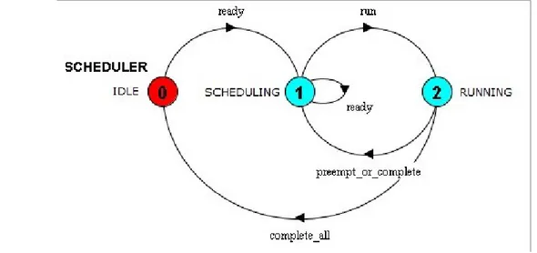
Figure 8: The scheduler automaton [14, p. 120]...24
Figure 9: The simplified AADL threads' execution model [4, p. 168]...25
Figure 10: Thread behavior [23, p. 285]...27
Figure 11: OSATE plug-in architecture [30]...29
Figure 12: Main simulator components...36
Figure 13: The scheduler automaton...37
Figure 14: The thead automaton...38
Figure 15: Simulator workflow...40
Figure 16: Structure of the State pattern [13]...41
Figure 17: The State pattern implemented for Scheduler...41
Figure 18: The State pattern implemented for Thread...41
Figure 19: Thread automation in Uppaal [15]...43
Index of Tables
Table 1: System-level specification of the flight control system...14
Table 2: Implementations of system components in the flight control system...15
Table 3: Hardware components specification of the flight control system...16
Table 4: Process specification of the flight control system...17
Table 5: Thread specification of the flight control system...18
Table 6: State changes mapping between scheduler and thread...39
Table 7: Inheritance of thread properties in AADL...44
Section 1. Introduction
In this introductory section we present the purpose of this thesis work and the problems it solves. We start with the motivation behind this paper in section 1.1, followed by the goals and tasks set to be delivered as an end result in section 1.2. In section 1.3 we discuss the benefits this work provides, and finally in section 1.4 we outline the structure of the rest of the paper.
1.1 Motivation
There are a lot of industries nowadays where safety-critical software intensive systems are used. These include, but are not limited to, automotive and aircraft industry, medicine, and autonomous systems. Fault in such systems can be fatal and lead to severe damage and/or loss of human lives. Therefore fault-tolerance should be considered at all stages of the system development, starting from the analysis and design. Verification techniques should be obtained that ensure the consistency of the software system across its phases of development. To ensure that, special attention is paid to the description of the system architecture and its non-functional requirements. Different languages and tools have been developed for that purpose across the years.
One of these is the Architecture Analysis and Design Language (AADL) – used to describe the design of real-time embedded systems and safety-critical systems [25]. Developed by the Society of Automotive Engineers, it is currently widely used in automotive and aircraft industry. Among the users of the language are the European Space Agency and Airbus France [33]. Some of the other industry projects based on AADL can be seen in Figure 1 below. The support of the Software Engineering Institute can only increase its popularity in the future. AADL provides means to design systems through abstractions of components and the interactions between them, and to analyze the specified systems through the semantic definitions of the language.
In the context of safety-critical systems, analysis of a system is at least as important as its design. Yet, analysis of AADL specifications is only feasible through time-consuming and error-prone manual labor, due to the lack of an automated tool for that. This makes it difficult to ensure the consistency of the system across its development phases. Thus problems will arise if the implementation of the system doesn't conform to the design and as a result doesn't meet important safety constraints. The same is true for the consistency between the analysis and design phases. Therefore it is extremely important to have a tool that helps the verification and validation of a system as it moves from one development phase to another.
As such a tool, an AADL simulator would be very valuable by enabling examination of the possible dynamic executions of an AADL specification. This would allow us to verify the correctness of an AADL specification based on the behavior it shows. While not in the scope if this work, at a later stage it would also be possible to perform changes in the execution model that will be directly reflected in the original AADL specification. Thus the tool will help software engineers to quickly detect problems at an early phase and fix them on the fly. This should improve the reliability of the software system, while decreasing its development costs.
Having in mind everything mentioned so far, in this work we focus on developing a simulator for AADL in Java. It would expect an AADL specification of a software system as an input and would simulate the dynamic execution of that system. Java was chosen as a target language because of its platform independence and language characteristics. It would allow us to focus on modeling the software components, where most of the design problems come from, without going into unnecessary detail about the execution platform. As an end result, we would have a useful tool for exploring the dynamic behavior of software systems specified in AADL.
1.2 Goals and tasks
The main goal of the thesis work is to create a simulator of AADL in Java. It should receive an AADL specification of a software system as an input and simulate the execution of the threads in that specification. A Java model will be created that conforms to the original AADL model, but it should also give the possibility to explore its dynamic behavior and ensure that all properties and constraints set in the specification are met. The output from the simulator should allow easy detection of inconsistencies in the execution model of the system. More detailed requirements about the simulator are provided in Section 4. Before reaching this goal, a few prerequisites should be met that we will now review.
The first of them is acquiring knowledge of AADL and its syntax and semantics. In order to do that, a basic specification for a simple system is presented in section 2.2. Since AADL is used primarily in the automotive and aircraft industries, we have chosen to describe a simplified flight control system for a plane. While far from similar systems in real use, it will help us to highlight the main constructs in AADL that are needed for reading a simple specification. They should be enough to give the reader an initial understanding of the language without going into unnecessary detail about rarely used features. We also describe how synchronous and asynchronous aspects of the software system can be modeled in AADL and what are the challenges in their simulation in section 2.3. Part of the simulator is a compiler that reads the AADL specification, validates it and transforms it to a Java model. We take a look at the individual steps needed for that, with focus on parsing the
input. This has been already implemented in a previous project, but we need to get acquainted with it in order to use it. Therefore we review the different kinds of algorithms used for parsing and explore how they work. After this task is completed, we will have acquired basic knowledge in compiler theory that is needed for the creation of the simulator. The results from this task are described in section 3.3.
As already mentioned, we base our work on a previous project that will take care of parsing the input. To do that, it uses a compiler-compiler tool that transforms the AADL specification to a Java model. We take a look at what these kind of tools provide and present a list of the most popular of them. We pay more attention to the one used and describe how it works and how we apply it in our particular case in section 3. With this task, the practical prerequisites for creating the simulator are fulfilled.
Before we can start working on it, however, we need some theoretical research in model transformation without loss of semantics. Since this is the first action our simulator performs, we should ensure it is correct. To do that, we make a detailed literature review of previous works in the area in section 2.4. There are few papers on simulation of AADL systems, but many on model transformation, which is actually part of our simulator. We use them as a basis for our actions in the transformation from AADL to Java and benefit from what other authors have already discovered in their works. After this research is done, the requirements for the simulator behavior are defined in section 4.
In order to prove that we have achieved our main goal, we examine a case study and run it through the simulator created. For this, we are using the flight control system specification presented in section 2.2. We should be able to parse the input correctly and make judgments about model properties. Results from this task are described in section 5.3. A summary on the fulfillment of these tasks is provided in section 6.1.
1.3 Benefits
The benefits gained from this thesis work are directly linked to the motivation for its creation as well as its goals. First, we obtain a useful tool for exploring the dynamic execution of software systems specified in AADL. There is no such tool available in the Java language, so the one created can also serve as a basis for future work. By itself, it can be helpful in several different ways.
One of the possible uses of the created simulator is just for transformation of an AADL specification to a Java model. This can then be used as an input to other tools for model analysis or transformation. An even more simple usage is for validating syntactical correctness of the AADL model – in this case only the parser sub-component of the tool will be used.
Naturally, the main benefit is that errors in the specification that expose themselves during run-time can now be discovered by simulating the dynamic execution. Thus any properties or constraints that won't be valid can be changed and, if needed, the model can be modified as well. In a future extension of the simulator, it can be possible for changes in the execution model to be reflected in the original AADL model, thus reducing the time for fixing issues. In any case, detecting problems at such an early phase in the software development will reduce the costs and increase the reliability of the system. The simulator has a few unique benefits as well – first, it covers asynchronous parts
of the language as well, and second – it uses an internal clock for precise measurement of time. There are indirect benefits from the work as well. Different sections of the thesis report can be used as an introduction to specific problems. Section 2.2 can be used as a general introduction to AADL, and section 3.3 – as a basic description of parsing algorithms and compiler-compiler tools. Section 2.4 provides a review of previous work on model transformation.
In summary, this thesis provides readers with good starting points to explore AADL, compiler theory and model transformation. It also delivers a useful simulator tool that can be used on its own, or as a basis for future research.
1.4 Report structure
The structure of the report in its first part follows the preparation tasks completed as a prerequisite for creating the simulator. The second part of the report goes into more detail in the development phases of the tool – analysis, design and implementation.
In section 2 we present an overview of AADL model transformations, consisting of three parts. The first part, in section 2.1, contains basic definitions of the technologies introduced and specific terms related to them. Section 2.2 presents the AADL language by building an example specification for a flight control system and in section 2.3 we present the synchronous and asynchronous aspect of the language. In the last sub-section, 2.4 we review previous works on AADL model transformations and draw some conclusions from them.
Section 3 is dedicated to the technologies used in this thesis work. First, we provide the requirements for the tools that we will need in section 3.1. Then in section 3.2 we present the choice that we have made. In section 3.3 we present an introduction to grammar parsing and in the final section 3.4 we summarize the technologies choice.
Section 4 is concerned with the analysis phase of the simulator development. In its first sub-section, 4.1 we present the previous project that this work relies upon. Then in section 4.2 we define a subset of the AADL language that we will use in this thesis. In the next two sections we present the requirements for the simulator – functional and non-functional ones in section 4.3 and use case scenarios in section 4.4. A summary of the analysis can be found in section 4.5.
The design and implementation of the system are the main topic in section 5. It starts with a description of the overall structure of the simulator in section 5.1. Then the design patterns used are presented in section 5.2. Section 5.3 considers the execution semantics for the simulator and how they relate to previous work. In section 5.4 the flight control system is used as a case study for the simulator. Finally a summary of the design and implementation is provided in section 5.5 and the contribution of the simulator to the field is presented.
Section 6 serves as a conclusion to the thesis. It contains a summary of the work done in section 6.1 and suggestions for future improvements in section 6.2. Section 7 contains the list of references used in the paper. Section 8 provides appendices to the work, which include an example AADL specification, setup instructions for the development environment, and sample simulator output. The simulator code itself is available separately as an archive file.
Section 2. Overview of AADL model transformations
In this section we introduce the problem area that this paper is concerned with. We start by providing some basic definitions in section 2.1, followed by an AADL specification example of a flight control system in section 2.2 to illustrate the main concepts in the language. In section 2.3 we discuss the synchronous and asynchronous aspect of the language and in section 2.4 we provide a detailed literature review of previous works on AADL model transformations.
2.1 Basic definitions
AADL, standing for Architecture Analysis and Design Language, is a modeling language used to
describe the architecture of a software system. It consists of textual and graphical descriptions of three types of components – software, execution platform and system. It is widely used in industry and very effective in model-based analysis of safety-critical systems [11, pp. 4-5].
CAN bus, standing for Controller Area Network bus, allows “micro-controllers and devices to
communicate with each other within a vehicle without a host computer” [8].
Compiler is “a computer program (or set of programs) that transforms source code written in a
programming language (the source language) into another computer language” [6].
Compiler-compiler is “a tool that creates a parser, interpreter, or compiler from some form of formal
description of a language and machine” [7].
Electronic Control Unit (ECU) is a generic term for embedded software systems in a motor vehicle
[10].
Fixed priority pre-emptive scheduling is a scheduling policy in which the O/S assigns a fixed
priority rank to every process, and the scheduler arranges the processes in the ready queue in order of their priority [26].
Fly-by-wire is a flight control system of an aircraft where the movement of the pilot controls are
converted to electronic signals and computers determine how to move the actuators in accordance with those signals [12].
Lexer, or lexical analyzer is a program or function which converts a sequence of characters into a
sequence of tokens [16].
Model transformation is “a […] way of ensuring that a family of models is consistent, in a precise
sense which the software engineer can define” [19].
Parser is “one of the components in an interpreter or compiler that checks for correct syntax and
builds a data structure [...] implicit in the input tokens.” The parser often uses a separate lexical analyzer to create tokens from the sequence of input characters. [21]
Parsing is “the process of analyzing a text, made of a sequence of tokens [...], to determine its
grammatical structure with respect to a given [...] formal grammar.” [21]
Safety-critical system is a system, a failure in which can result to serious injury or death of people
or severe damage to equipment [17].
Scheduler is a CPU component that decides which of the ready, in-memory processes are to be
2.2 An AADL example
As already mentioned, the Architecture Analysis & Design Language (AADL) is a modeling language for describing software system architectures. It was introduced in 2004 by the Society of Automotive Engineers (SAE) and refined in 2009. As its name suggests, it is used for analyzing and designing system architectures, primarily of complex real-time embedded systems. More precisely, it is created to:
• “specify and analyze real-time embedded systems, complex systems of systems, and specialized performance capability systems”
• “map software onto computational hardware elements” [11, p. 4]
The language is based on a “component-connector paradigm that describes components, component interfaces and the interactions (connections) among components” [14, p. 107]. Hence, the main structural entities in AADL are components, there being three types of them:
• software: process, thread, thread group, data and subprogram;
• execution platform: processor, bus, memory and device;
• composite: system.
Components are described in two ways. Firstly, component types define the interfaces for external communication using features, flow specifications, modes and properties. Secondly, component implementations define the internal view of the component through its subcomponents, connections and flows. The component implementation should conform to the component type, but it can override modes and properties. In an AADL specification, components usually form a hierarchy, with the system component at the top level. The components that we focus on in our work are described below:
• process: represents a virtual address space, has to contain at least one explicitly defined
thread;
• thread: carries execution semantics, schedulable within a process; this is the major
component of concern in our simulator; • data: represents a data type in the source text;
• processor: responsible for scheduling and executing threads;
• memory: responsible for storing data and programs;
• bus: responsible for communication between execution platform components;
• device: provides an interface to the external environment, often modelled with software
components;
• system: allows creating hierarchical structure by composing other components; usually
every AADL specification has a top-level system component.
Although AADL has both textual and graphical parts, the textual is more widely used, as it provides a possibility for formal analysis and automated tools processing.
The elements of component types and implementations that our simulator is concerned with are as follows:
• features declare the external interfaces of a component, these can be ports, subprograms, or
shared access to bus/data;
• modes allow the component configuration to be changed at runtime;
• properties express internal characteristics of the model;
• subcomponents support the hierarchical structure of AADL specifications;
• connections describe the communication between components.
All these AADL elements and their relationship are shown in Figure 2 below. Our simulator will support only a subset of the AADL standard, which is defined in section 4.2.
In order to ease the understanding of the concepts described, we will take a look at a simplified example of a software system specified in AADL. We will examine its textual and graphical representation in AADL and thus introduce the main syntax constructs of the language. The system we present is a flight control system of a plane and is detailed in the next sub-sections.
2.2.1 Basic concepts of a flight control system
The most important basic controls that a pilot uses to fly a plane are usually a yoke and two pedals. They are wired to several rudders on the plane that handle its movement. These can be seen on Figure 3 below:
• ailerons on the wings, controlling plane rolling (blue); the two ailerons move in opposite
directions and change the lift power of the wings;
• elevator on the horizontal stabilizer, controlling plane lifting and lowering (yellow); the
elevator forces the nose of the plane to lift or lower;
• vertical fin rudder on the vertical stabilizer controlling turning left and right (red); this
rudder forces the nose to go left or right;
These are ususally wired together by a hydraulics system, but for the sake of this example, we will review a fly-by-wire configuration where a computer is used to transfer the signals between sensors and actuators. The yoke can move left and right, which would make the plane roll left or right using the ailerons. It can also move back and forward, which controls the elevator for lifting and lowering the plane. The pedals cannot be pressed in the same time and control the vertical stabilizer for making left and right turns [15, p. 31].
Another feature that planes usually have is auto-pilot. It can be triggerred on or off by a press of a button and will override the manual controls of the plane. It should be noted that these controls are often used simultaneously. Of course, there are a lot more controls in a real plane, but our goal is to provide a simple system that can be used for illustration. So with these concepts in mind, we will model a flight control system with three sensors (for the yoke, pedals, and the auto-pilot trigger button) and three actuators (for the different type of rudders described above). Communication between the sensors and the actuators will be through binary data and events transmitted electronically. More detailed description of this system follows in the next sub-section.
2.2.2 Flight control system description
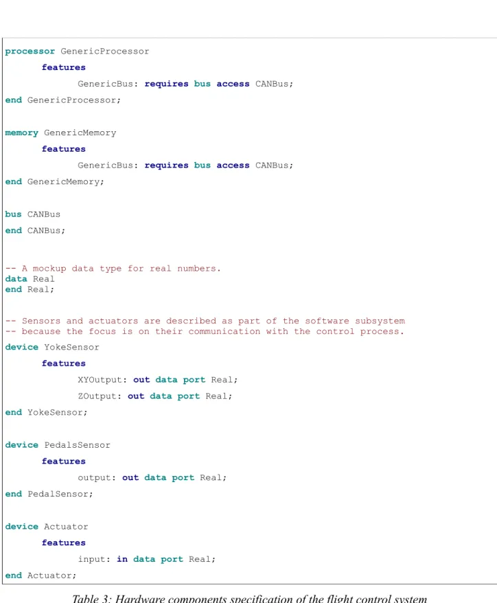
In this example we will design an architecture of an electronic control unit (ECU) for a plane. The ECU consists of one processor scheduling and executing threads/tasks, one piece of memory to store data, and one CAN bus to interconnect hardware components of the ECU as well as the required sensors and actuators. The functionalities of the intended ECU will handle the “flight-control” of the plane. It will manipulate the airplane rudders (aileron rudders, elevator rudder and vertical fin rudder) based on the control units (yoke and pedals). It will also support auto-pilot mode which is triggerred by a button. Hence, sensors needed are one for the yoke, one for the pedals, and one for the auto-pilot trigger. Needed actuators are one for the aileron rudders, one for the elevator rudder and one for the vertical fin rudder.
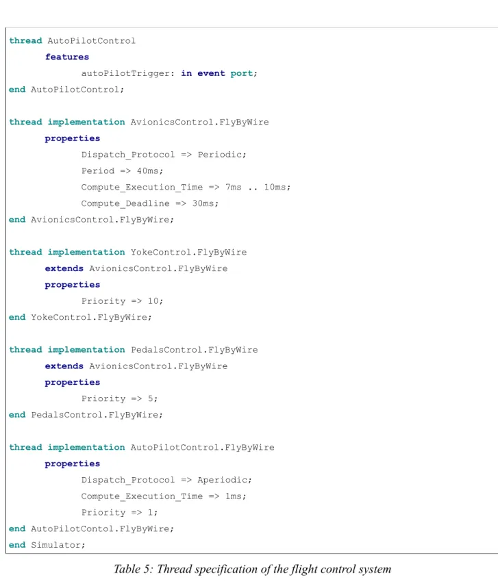
The software providing the functionalities consists of a single process with three threads, one to control the ailerons and elevator according to the yoke, another to control the vertical fin rudder according to the pedals, and third to override the controls when autopilot is turned on. Both manual control threads have periodic dispatches in 40 milliseconds, a compute execution time range of 7 to 10 milliseconds and a compute deadline of 30 milliseconds. The autopilot thread has an asynchronous dispatch on the event of a button press and a compute execution time of 1 millisecond. The “yoke” thread has a higher priority with respect to the “pedals” thread, and the “autopilot” thread has the lowest priority. Each thread communicates with its corresponding sensors and actuators through data ports. The "autopilot" thread has an input event port that will receieve an event on a press of the auto-pilot trigger.
2.2.3 The flight control system in AADL
We will review the specification of the system in a top-down approach, starting from the system level until we get to the lowest component level, in our case – the threads. In Table 1 on the next page we define two system types – Software and ExecutionPlatform that communicate over a shared CAN bus. The hardware sub-system provides access to the bus while the software one requires it, thus showing how interaction between the two systems is achieved. As you can see, the bus access is part of the component features. In the system implementation FlightControlSystem.FlyByWire we can see how the flight control system is comprised of two sub-systems. The idea behind this separation is to bring the attention to the more detailed description of the software sub-component while still showing the mapping between software and hardware. This also shows the hierarchy formed between the components – a system at the top level contains two sub-systems on the level below, which contain the rest of the components.
We can see that there are two different notions for components in AADL. As already mentioned, component types specify the external interface of a component, while component implementations represent the realization of the component [25, pp. 34-39]. The implementation should comply with the type, just like a class implementing an interface in an object-oriented language. In this particular example, the type defines features, which are external to the component, and the implementation defines subcomponents, or its internal structure.
We also see a package defined – just as packages in Java, it serves as a namespace that limits scope. Packages can have public and private parts and in our case the whole system is defined in the public part of the package. The ending clause is not shown in this table. As far as syntax is concerned, in
the code examples that follow component keywords are shown in bold turquoise, while AADL keywords are shown in bold blue.
package Simulator public system FlightControlSystem end FlightControlSystem; system Software features
BusAccess: requires bus access CANBus;
end Software;
system ExecutionPlatform
features
BusAccess: provides bus access CANBus;
end ExecutionPlatform;
system implementation FlightControlSystem.FlyByWire
subcomponents
SoftwarePart: system Software.FlyByWire;
HardwarePart: system ExecutionPlatform.FlyByWire;
end FlightControlSystem.FlyByWire;
Table 1: System-level specification of the flight control system
In Table 2 on the next page we can see what sub-components the two sub-systems have. In the ExecutionPlatform.FlyByWire implementation we have the hardware sub-components defined as well as the mapping between the two sub-systems. We can see that through the binding properties the software process that contains the executable threads is set to run on the processor and memory from the hardware sub-system.
In the software part, we have a single process that will handle the flight control and devices for each sensor and actuator. It is worth noting that the actuator devices are all instances of the same component, which is due to the fact that they have the same external interface. This shows how good practices in object-oriented programming can be transferred to AADL specifications. While in AADL devices are formally hardware components, they are often included in the description of the software sub-system. This is because the focus of the specification is usually on the communication between devices that is handled by the software process(es).
As seen in the table, there is a direct mapping between the sensors output and the process in ports as well as between the process out ports and the actuators input. This looks much like a pipeline, where we are transferring data from the component that provides it to the one that processes it. This data flow is described with the help of connections which consist of mappings between data ports. The names of the component implementations start with the name of the component types, followed by an identifier – that would be similar to FlyByWire implements Software in Java for example.
system implementation Software.FlyByWire
subcomponents
FlightControl: process FlightControl.FlyByWire; Yoke: device YokeSensor;
Pedals: device PedalsSensor; AutoPilot: device AutoPilotSensor; Ailerons: device Actuator;
Elevator: device Actuator; VerticalFin: device Actuator;
connections
-- Direct mapping between sensors/actuators and process in/out ports.
data port Yoke.XYOutput -> FlightControl.yokeXYInput
data port Yoke.ZOutput -> FlightControl.yokeZInput
data port Pedals.output -> FlightControl.pedalsInput
data port FlightControl.aileronsOutput -> Ailerons.input;
data port FlightControl.elevatorOutput -> Elevator.input;
data port FlightControl.verticalFinOutput -> VerticalFin.input;
end Software.FlyByWire;
system implementation ExecutionPlatform.FlyByWire
subcomponents
CPU: processor GenericProcessor; RAM: memory GenericMemory; CANBus: bus CANBus;
ProcessConnection: process FlightControl.FlyByWire;
properties
Actual_Processor_Binding => reference CPU applies to ProcessConnection; Actual_Memory_Binding => reference RAM applies to ProcessConnection;
end ExecutionPlatform.FlyByWire;
Table 2: Implementations of system components in the flight control system
On the next page we can see the hardware components of the system in Table 3. Their specification is very brief because our focus is on the software part. This is also typical for early stages of a system's design, where the execution platform details might still be unknown. We have generic processor and memory that communicate via a CAN bus. Each sensor has the appropriate outputs as a real number and the actuator has its input in a similar manner. The real numbers are encapsulated in a data type, but we won't pay attention to its internal representation.
In Table 4 on page 16, process specifications are given. The component type defines the input/output data ports that the process has and the implementation defines three threads as sub-components. It also maps the process ports to the thread ports, just as in the thread implementation. Thus, as an end result we have the sensors input mapped to the corresponding in data ports of the thread that will handle it and the out data ports of the thread mapped to the corresponding actuator input. The only thing left to be specified in our system are the control threads themselves.
processor GenericProcessor
features
GenericBus: requires bus access CANBus;
end GenericProcessor;
memory GenericMemory
features
GenericBus: requires bus access CANBus;
end GenericMemory;
bus CANBus
end CANBus;
-- A mockup data type for real numbers.
data Real
end Real;
-- Sensors and actuators are described as part of the software subsystem -- because the focus is on their communication with the control process.
device YokeSensor
features
XYOutput: out data port Real; ZOutput: out data port Real;
end YokeSensor;
device PedalsSensor
features
output: out data port Real;
end PedalSensor;
device Actuator
features
input: in data port Real;
end Actuator;
Table 3: Hardware components specification of the flight control system
The control threads are shown in Table 5 starting on the next page. The in and out ports directly correspond to the process/sensors/actuator ports, as discussed previously. Since both threads have some common properties, we have decided to extract them in a base thread implementation AvionicsControl.FlyByWire that they extend. This shows how inheritance is supported in AADL. Both threads will have the common properties of the base implementation and add priority to it. This would work just as in an object-oriented programming language. Although the base type AvionicsControl is empty, we still have to define it. Otherwise we will get an error as the implementation wouldn't have a defining type. We also see the closing package statement here.
process FlightControl
features
yokeXYInput: in data port Real; yokeZInput: in data port Real; pedalsInput: in data port Real; aileronsOutput: out data port Real; elevatorOutput: out data port Real; verticalFinOutput: out data port Real;
end FlightControl;
process implementation FlightControl.FlyByWire
subcomponents
YokeControl: thread YokeControl.FlyByWire; PedalsControl: thread PedalsControl.FlyByWire; AutoPilotControl: thread AutoPilotControl.FlyByWire;
connections
-- Direct mapping between process and threads in/out ports.
data port yokeXYInput -> YokeControl.aileronsInput;
data port yokeZInput -> YokeControl.elevatorInput;
data port pedalsInput -> PedalsControl.verticalFinInput;
data port YokeControl.aileronOutput -> aileronsOutput;
data port YokeControl.elevatorOutput -> elevatorOutput;
data port PedalsControl.verticalFinOutput -> verticalFinOutput;
end FlightControl.FlyByWire;
Table 4: Process specification of the flight control system thread AvionicsControl
end AvionicsControl;
thread YokeControl
features
aileronsInput: in data port Real; elevatorInput: in data port Real; aileronsOutput: out data port Real; elevatorOutput: out data port Real;
end YokeControl;
thread PedalsControl
features
verticalFinInput: in data port Real; verticalFinOutput: out data port Real;
thread AutoPilotControl
features
autoPilotTrigger: in event port;
end AutoPilotControl;
thread implementation AvionicsControl.FlyByWire
properties Dispatch_Protocol => Periodic; Period => 40ms; Compute_Execution_Time => 7ms .. 10ms; Compute_Deadline => 30ms; end AvionicsControl.FlyByWire;
thread implementation YokeControl.FlyByWire
extends AvionicsControl.FlyByWire
properties
Priority => 10;
end YokeControl.FlyByWire;
thread implementation PedalsControl.FlyByWire
extends AvionicsControl.FlyByWire
properties
Priority => 5;
end PedalsControl.FlyByWire;
thread implementation AutoPilotControl.FlyByWire
properties Dispatch_Protocol => Aperiodic; Compute_Execution_Time => 1ms; Priority => 1; end AutoPilotContol.FlyByWire; end Simulator;
Table 5: Thread specification of the flight control system
The full AADL specification of the system can be found in Appendix 1. It demonstrates the most often used components in the language, its syntax, and basic concepts such as inheritance of properties and type implementation. It also shows the most important timing properties of thread that are related to the execution model of the specification. These will be read by the simulator as described in section 5.
Of course, real systems are much more complex and hence harder to analyze. After presenting the graphical AADL representation of our example, we will take a look at the model transformation techniques used to help analyze such complex systems.
Figure 4 below presents the graphical notation of AADL. You can see the different components and how they are represented:
• Systems are represented by rounded rectangles; • Processes are represented by parallelograms;
• Threads are represented by parallelograms with dashed outline; • Processors are represented by parallelepipeds;
• Memories are represented by cylinders;
• Buses are represented by double-pointed arrows;
• Data ports are represented by filled triangles pointing in the direction of the port;
• Connections are represented by lines, labeled with the type of the connection (B is for bus, D is for data).
The data ports are not labeled because of lack of space. The features for providing and requiring bus access of the CPU, RAM and CAN Bus are not labeled as well for the same reason. The thread responsible for triggering the auto pilot is also omitted.
2.3 Synchronous and asynchronous aspects of AADL
AADL and its language constructs support the modeling of both synchronous and asynchronous software systems. However, model verification for asynchronous systems proves problematic, as we will explore below. This is a challenge for the wide acceptance of the AADL standard, because real-world systems in industry usually have asynchronous elements.
AADL provides a Thread component that models a concurrent task or an active object [25, p. 77]. It has a set of predeclared properties that describe the thread's configuration. The property that is of a particular importance in this section is Dispatch_Protocol, which can take one of a set of predefined values. Periodic threads are used in synchronous systems – they are dispatched at a given interval of time, determined by the Period property of the thread. Communication is synchronized and carried out through input/output data ports. This means that data is transmitted at a known time – either at thread completion (immediate connections) or at a thread's deadline (delayed connections) [4, p. 168]. This makes it easy to predict the execution model of synchronous systems, as all timing properties are known beforehand and there is a single path of execution that can be simulated.
Threads can also be aperiodic or sporadic, meaning that they are dispatched at irregular intervals of time, unlike periodic threads. The dispatch is triggered by an event and a minimal interval of time can be set between dispatches of sporadic threads [4, p. 168]. Communication is carried out through input/output data and event ports. Unlike periodic threads, data and events can be transmitted at any time. AADL also supports background and hybrid threads, but we will not review them in this work.
Now we can see the difficulties with model checking in asynchronous systems. First of all, non-determinism exists in the execution of the system. In other words, there are infinite number of possible execution paths in the system. An event triggering the dispatch of an asynchronous thread can occur at any time in the life cycle of the system. Thus usual techniques are not able to correctly verify the model. We also lack the basic assumptions that are true for the synchronous systems: zero time computation and instantaneous communication [23, p. 286]. These, together with the determinism in concurrency make their models much easier to verify.
As we will see in the review of previous works, there is a lot of effort done on synchronous systems and far less progress made on asynchronous ones. In a lot of model transformations only the synchronous aspect is concerned, with the asynchronous given as a subject of examination in future works. Besides, most previous works are concerned with model transformations and not simulation, which is why the current work is a good contribution to the field.
2.4 Previous works on AADL model transformation
In this sub-section we review previous works concerned with AADL model transformation. We introduce how synchronous and asynchronous systems are represented in the language and how we can transform an AADL specification to a model in another language. For each transformation, we also quickly review the formally defined semantics, if such are introduced. At the end of the section we summarize our findings.
2.4.1 Transformation from AADL to SystemC
SystemC is a system-level modeling language that enables simulation of concurrent processes. Although strictly speaking it is a C++ class library that provides an event-driven simulation kernel, it is popularly considered a language on its own [27]. A modeling tool called AADS-T has been developed at the University of Cantabria in Spain to convert an AADL specification to a SystemC model [2]. In order to do that, an intermediate model is generated by the tool, described in POSIX / C++ and XML. This model is then fed as an input to another tool – SCoPE – that can check the model constraints and perform a simulation. The relationships between these tools and OSATE are shown in Figure 5 below. The process of conversion from an AADL model to the intermediate model is described in the work by Varona-Gomez, which is the first paper in our literature review.
The paper starts with the motivation behind AADL simulation, claiming that this is the only way for some properties of the model to be obtained. Only simulation in real conditions can detect locks, missed deadlines and other problems that arise after complex interaction between components. We have also considered this in the motivation section for our work, stressing on the fact that the earlier these problems are discovered, the less the cost for their fixing will be.
The transformation methodology described by Varona-Gomez allows for iterative refinement of the AADL specification as performance analysis is carried out. A visual depiction of the process is presented in Figure 6 on the next page. The aforementioned AADS-T and SCoPE tools are used for the performance analysis. After refinement is completed, a SystemC model file can be generated from SCoPE. This model captures the fundamental dynamic properties of the initial system, but no formal semantics are provided to validate the model transformation. Besides, the tool can only recognize a subset of AADL, so future research is needed in the area. The contribution of this paper
to our work is providing an insight about modeling AADL threads, which carry the execution semantics of AADL, as POSIX threads.
2.4.2 Transformation from AADL to BIP
BIP, standing for Behavior, Interaction, Priority, is a component-based framework for modeling complex systems [22]. It consists of a layered component model, a language notation for describing it, and a tool set for working with BIP programs [5, p. 5]. Since model-checking tools are available for the framework, it can be used for verification of software systems by validating the BIP model – for example ensuring that no deadlocks will occur. Translation from AADL to BIP models takes benefit from the formally defined operational semantics of BIP that AADL lacks. Such a translation and a tool for it are examined in the paper by Chkouri that we will now review.
After providing an overview of AADL and BIP, the paper studies the transformation between the models. It is split into 5 parts based on the AADL specification - software components, execution platform, system component, behavior annex and connections. For each of these categories, the model transformation is described in terms of the resulting BIP model that is presented visually as well. An example of that can be seen in Figure 7 on the next page. It presents the BIP model of thread behavior. Similar models are available in the paper for other components as well.
With the model transformation defined, a tool is developed in Java that does automatic conversion of the models and ensures they stick to the corresponding meta-model. Then the BIP model is used as an input for generating C/C++ code that can be executed. After that an exploration engine executes that code and generates a Labeled Transition System that can be used for further model-checking. Simulation of the interactions and additional verification can be performed as next steps. To prove the correctness of the tool, the paper finally examines a case study of a flight computer. With the help of the tool lack of deadlocks, thread deadlines and synchronization between components are verified.
The paper provides a good introduction into model transformation. Since BIP has operational semantics defined in terms of labeled transition systems, the transformation can be used as a basis for model verification, as the case study shows. With regards to our work, the paper reviewed presents a good description of AADL thread and process behavior in terms of BIP. This can serve as a basis of defining the execution semantics for the simulator we are developing.
2.4.3 Transformation from AADL to Uppaal
Uppaal is a toolbox for modeling, validation and verification of real-time systems [31]. It uses a network of timed automata extended with discrete variables to model software systems [14, p. 108]. Since the Uppaal language has formaly defined and implemented semantics, it is an appropriate choice for verification of the properties of real-time systems. A transformation from an AADL model to an Uppaal automaton is described in the paper by Johnsen et al. that we will review now. The paper presents a technique for verification of AADL specification after it is transformed to an Uppaal representation. It provides a short introduction in the two languages and a verification technique and its criteria before taking a look at the transformation itself. We will focus our review on the way an AADL specification is converted to an Uppaal automaton, as this is the part that relates to our work.
As already mentioned, the key reason for the need of this transformation is that AADL lacks formal
and implemented semantics. Therefore the paper defines mapping rules from AADL constructs to timed automata in the Uppaal modeling language. The transformation rules are limited to only considering synchronous interaction with preemptive scheduling.
The transformation rules are defined as a series of Uppaal automatons. The first one describes different thread states and how AADL threads are mapped to such an automaton. The second is a scheduler automaton which can be used for mapping AADL processor components since they are responsible for scheduling and executing threads. Those two form the basis of simulating AADL specifications with a synchronous execution model. Additional refinements are made for AADL models that include modes, behavior annex descriptions or subprogram calls, although without fully defined semantics.
One of the Uppaal automatons is presented on Figure 8 below. As we can see, there are variables associated with every state that express the execution semantics. This automaton can serve as an example of the scheduler automaton that we are implementing in our work, although it is too complex for our purposes. We will use a simplified scheduler automaton as shown in section 5 of the thesis.
The asynchronous aspect of AADL is not considered in this paper due to its complexity caused by the nondeterminism in execution. Nevertheless, the paper provides a well defined semantics for the dynamic behavior of systems specified in AADL that can be used as a base for formal analysis and model checking of the system at an early phase of its development. It can be combined with the simulator work in our thesis and provide formal definition of the automata we have used.
2.4.4 Transformation from AADL to RTSJ
RTSJ, standing for Real-Time Specification for Java, is a Java library that is designed to support
real-time applications by a suitable set of scheduling properties [24]. It provides enhanced thread support and a memory management mechanism that avoids the nondeterminism of garbage collection. An overview of the language and a transformation from AADL specification to an RTSJ model are presented in the paper by Bodeveix, which we will review now.
The paper follows the usual structure – an overview of the source and target languages for the transformation, followed by a presentation of the mapping rules themselves. As usual, we will focus our review on the latter. Only a subset of AADL is reviewed in the paper, excluding hardware components and presenting a simplified execution model of AADL threads.
The mapping is expressed in terms of Java interfaces, thus providing a model only, without a proof of its semantic corectness. Different kinds of threads, ports and port connections are presented in sequence. There is a direct mapping between an AADL component and a given interface. A few system classes are needed as well to support the execution semantics. These are a router class that keeps track of all connections and classes for each type of AADL thread (periodic, aperiodic, sporadic).
The execution model of AADL threads is simplified and presented in Figure 9 below. It consists of only three states and a few transitions, but for the purposes of the paper is detailed enough. We have based our execution model on it, although we have made a few changes.
Most of the scheduling is handled by the RTSJ scheduler, but since it does not conform to the AADL execution model, some changes have been made manually. As an end result of the work so far, there is a RTSJ model implementing the semantics of a subset of AADL, but not specifying them in a formal notation. That is what the next section of the paper does.
Figure 9: The simplified AADL threads' execution model [4, p. 168]
TLA+ is chosen as a language to describe the semantics in. An abbreviation of Temporal Logic of Actions, it is a logic language for specifying concurrent systems [29]. The rest of the paper defines AADL execution semantics in terms of TLA, again limited to the subset of the language that is translated to RTSJ. Thus, the paper provides two outputs as a reference for future works: a model transformation from AADL to Java and a TLA+ description of the AADL execution semantics (concerning threads and ports). Therefore it can serve as a basis of defining the execution semantics in our simulator.
2.4.5 Transformation from RTSJ to Uppaal
Since we have reviewed a transformation from AADL to RTSJ and from AADL to Uppaal, it might be beneficial to review one from RTSJ to Uppaal as well. It is the primary topic of interest in the work by Dos Santos, which we will try to summarize. Though the paper provides an introduction to Uppaal and the scheduling model of RTSJ, we will jump directly to the semantic definition on non-periodic real time threads in RTSJ.
The formal model uses a three-layer architecture, consisting of application, component and scheduler level. Automata are used at each level to describe real-time thread components. After a detailed definition of the model, formal analysis is performed on it. As an end result of the work, formal semantics of non-periodic RTSJ threads defined via Uppaal timed automata constructs. Important model properties are verified, such as the lack of deadlocks.
This paper can be used together with the previous one for translation of AADL specifications to RTSJ and verification of the model with the help of the semantics defined. However, it still doesn't cover all aspects of AADL and further work is needed.
2.4.6 Defining AADL mode automaton
Something most of the mentioned papers lack to include is semantics for AADL modes. They are often considered a non-essential feature of the language and thus left for other works. There is, however, a paper by Rolland that provides a formal TLA+ specification to describe the AADL modes concepts. Modes are included in AADL to support the dynamic change in the configuration of a software system. However, the behavior of a system during a mode transition is not formally specified. This is the main purpose of the paper under review.
The work starts by providing abstract definitions of atomic transitions, breaking transitions, critical and zombie threads, preemption and priorities. Then a formal TLA+ specification is presented that conforms to these abstract definitions. The thread behavior abstraction is presented in Figure 10 on the next page. It can serve as a good example on how to extend our thread automaton when modes are included at a further stage of development.
Due to nondeterminism in asynchronous systems, it is explicitly noted that mode switches there require more attention. The mode specification presented in the paper does not actually directly apply to AADL modes but can serve as a basis for easy extension. Timing aspects are another issue that needs further exploration. In summary, the paper provides a good introduction to formally defining the semantics of AADL mode transitions, but further research is needed.
2.4.7 Summary of model transformations
All of the work done so far regarding AADL model transformations leaves some open questions for future research. In most cases these are related to the asynchronous aspects of the language or to the execution platform components. However, the formally defined semantics presented in the different papers can serve as a basis for defining the semantics our simulator will use. We will review these in more detail in Chapter 5.3 as we present the design and implementation of the simulator.
Section 3. Technologies used
In this section we describe the technologies and tools used in the course of preparing this paper. In section 3.1 we present the requirements of what we need and in section 3.2 we make a choice among the different tools available. In section 3.3 we describe the parsing algorithm used and in section 3.4 we present a summary of what we are going to use.
3.1 Required tools
Throughout the process of creating an AADL simulator in Java, we will need the support of some technologies and tools we will now present. The core of our work should be done in an Integrated Development Environment (IDE) that supports the AADL language. It has to provide syntax highlighting, error checking and compilation of the text model. It is a plus if it also includes a graphical editor and allows conversion between text and graphical representation. Helper features such as code completion are not a requirement, but will be considered an advantage.
For the work on the simulator itself, we will need a IDE for development in Java. It has to provide the standard features of an IDE that we already mentioned in the previous paragraph – syntax highlighting, error checking, code completion, etc. Since most of the tools available do that, the choice here might depend on integration with other tools, personal preferences, or previous experience.
Before we present the next tool that we need, we need to provide a short description of how the simulator is expected to work. Since it will receive an AADL specification as an input, we need to parse that input and validate it. If the input is valid (i. e. syntactically correct), we need to compile a Java model out of it. The simulator then can explore the dynamic execution of the resulting model, which is our final goal. Since the first two steps are complex enough by themselves, we would like to use a helper tool for them, already employed in a previous project that we are basing our implementation on.
The kind of tool that we need is called parser generator or compiler-compiler. It takes a formal description of a language as an input, in our case – an AADL grammar in BNF (Backus-Naur form). The output it produces can vary – it can be a parser, an interpreter or a compiler [6]. The previous project mentioned produces a compiler that will transform the AADL specification to a Java model. The main requirement for the tool is to support a BNF grammar as an input Java as an output language. It should also provide error tracking and syntax highlighting of the grammar. Easy integration with other tools is a plus.
In the next sub-section we will review some of the available tools that meet the aforementioned requirements and choose the ones we will use.
3.2 Tools chosen
We will first review an IDE for working with AADL. The starting point is the AADL resource portal supported by Carnegie Mellon University [1]. For the purpose of this paper, we will stick to non-commercial tools that meet the basic requirements set above. We have two options – OSATE (Open Source AADL Tool Environment) and Furness Toolset. They both meet the requirements listed above, but OSATE has the advantage of Eclipse integration. This would allow seamless
integration with the other tools that we will use. Also, it includes the TOPCASED graphical editor, which supports conversion from textual AADL representation to graphical one and vice versa. The fact that the compiler project that we are building upon is based on OSATE confirms our choice. While it is possible to migrate to another tool, this would mean additional unnecessary overhead. The second choice is naturally Eclipse. Because OSATE is integrated with it, it can serve as a development environment for both Java and AADL. This should simplify and speed up development, and can also affect our next choice – the compiler-compiler tool. For it, Eclipse integration should be considered an advantage. This limits the tools available to only a few, among which ANTLR and Coco/R are the most popular. Our choice falls on ANTLR (ANother Tool for Language Recognition). Again, this choice was based on the previous project that we are using as part of our simulator. Since it originally uses ANTLR, sticking with it will be easier than migrating to another tool. Let's go into a little bit more detail on what these tools can do and how we can use them.
3.2.1 OSATE
As it is written on the AADL site, “SEI has developed OSATE as a set of plug-ins on top of the open-source Eclipse platform to provide a toolset for front-end processing of AADL models.” Some of the plug-ins are shown in Figure 11 below. It also shows how part of our simulator works behind the scenes. We provide a textual AADL specification that with the help of a parser is converted to a declarative AADL model with its corresponding XML representation. This is then converted to a Java EMF model used by our simulator. The parser component in the figure is generated by the ANTLR tool which we review in the next sub-section.
3.2.2 ANTLR
ANTLR stands for ANother Tool for Language Recognition. It is “a language tool that provides a framework for constructing recognizers, compilers, and translators from grammatical descriptions containing actions in a variety of target languages.” [3]. It expects a formal grammar in EBNF (Extended Backus–Naur Form) form as an input and constructs a language recognizer as an output. More precisely, it generates a lexer and a parser for that grammar.
ANTLR also allows code snippets to be added to the grammar that provide semantics to the syntactical constructs. Error recovery and reporting are sophisticated enough for any needs. In our work, this would allow us to construct the Java model by making use of the semantic rules that we can add to the grammar. It would also be easy to detect errors in the input AADL specification and point to the exact line where that occurs.
The popularity of ANTLR is due to the wide support of target languages on one hand, and the fact that it is open-source, on the other. It has evolved a lot throughout its 20 years of development by Terence Parr at the University of San Francisco. It also employs a really powerful parsing algorithm that allows a simplified syntax of the input grammar and the support of a wider variety of grammars. This algorithm is under review in the next section.
3.3 Grammar parsing
As it is a substantial part of the simulator, we will now review how parsing of the AADL specification in a Java model is done. This happens behind the scenes by the LL(*) parsing algorithm of ANTLR. In this section we provide a short introduction to different parsing algorithms and how they work.
Parsing is "the process of analyzing a text, made of a sequence of tokens [...], to determine its grammatical structure with respect to a given [...] formal grammar" [21]. In our case, we need to parse the input AADL specification in accordance with a well-defined AADL grammar to produce a Java output. The AADL grammar is created by a previous project that we are building on in this work. The parsing itself can be carried out in two approaches – top-down or bottom-up.
Bottom-up parsing starts from the smallest units first until the whole structure is recognized. In top-down parsing, it is just the opposite – the algorithm starts at the highest level of the parse tree. Two different kind of parsers are built on that notion – LR parsers are bottom-up and produce the rightmost derivation of the input while reading it from the left; LL parsers are top-down and produce the leftmost derivation of the input while reading it from the left [21]. The compiler-compiler tool that we are using in our project, ANTLR, uses LL parsing internally, which we will now explain in more detail.
An LL parser usually uses a lookahead constant k that determines the number of tokens read from the current position before determining the path in the parsing tree. The simplest parsers are LL(1), meaning that they look at the next symbol only before making a decision. However, they are limited to very simple grammars only. More often, LL(k) parsers are used, with k being an arbitrary number. Thus, a larger set of grammars, called LL(k) grammars can be recognized [18].
ANTLR takes this one step further, by implementing an LL(*) algorithm, which doesn't require k to be specified beforehand. Instead, it can look arbitrarily far ahead, thus enhancing the decision
making capabilities of the classical LL(k) algorithm [20, p. 263]. Lookahead decisions can easily be modeled using DFA (deterministic finite automata) and in the case of LL(k) algorithms, these automata are always acyclic. The LL(*) algorithm, however, allows loops in these DFA which serve for scanning the input arbitrarily far ahead [20, p. 268].
This simple enhancement provides a lot of advantages in terms of recognized grammars and also makes grammar writing easier. ANTLR is among the few tools that use this algorithm, which was another point in choosing him as the compiler-compiler tool in our project.
3.4 Summary
We have chosen Eclipse as the IDE for Java development that is needed for creating the simulator. The OSATE plug-in will be used for writing and validating AADL specifications. We will parse the AADL input and generate a Java model with the help of ANTLR, again as an Eclipse plug-in. Detailed instructions about setting up the development environment can be found in Appendix 2.
Section 4. Simulator requirements
As already noted, this work is based on a previous project for parsing AADL into Java. In section 4.1 we review what that project provides. Then in section 4.2 we define the subset of AADL that the simulator supports. In section 4.3 we clarify the requirements for the simulator and in section 4.4 we provide more detailed use-case scenarios. Finally, in section 4.5 we summarize the requirements.
4.1 The parser project
This work is based on a previous project developed at the School of Innovation, Design and Engineering (IDT) at Mälardalen University in Sweden. This previous work provides an AADL parser that covers a subset of the language and generates an EMF Java model coressponding to the input specification. Here we briefly review the structure of that project.
It is based on the Open-Source AADL Tool Environment (OSATE), which is supported by the Software Engineering Institute (SEI) [30]. Among other things, this environment provides an EMF model that corresponds to the AADL component model. To leverage it, a parser was developed at IDT that is based on ANTLR, the compiler-compiler tool that we reviewed in section 3.2.2. The parser itself is really simple – it consists only of an ANTLR grammar file that recognizes a subset of the AADL language. The subset covered includes all the major AADL components and their properties and is sufficient for the purpose of our work. The semantic rules in that grammar file take care of constructing the corresponding components in the EMF model
Our work uses the grammar file provided to parse the input with the help of ANTLR, in a similar way to the example provided in the project. On top of that it leverages the EMF model to determine the execution behavior to be simulated. Thus, we only need to take care of the simulator itself. In the next sections we review its requirements.
4.2 AADL subset supported
Before implementing the simulator, we need to define a meaningful subset of the AADL standard that it should support. This is necessary since AADL is too vast to fit within the scope of the current work. Our choice of supported AADL features should recognize software systems at least at the same level of detail as the flight control example that we reviewed in section 2.2. Its core should be the AADL thread component, as it carries the execution semantics of the model. Related components and properties should be included as well. Based on this reasoning, we define the AADL subset that the simulator supports to the following:
• Thread components and their implementations, as carriers of the execution semantics of the
model;
• Thread features: in and out data, event, and event data ports to support communication; • Thread properties related to timing and execution: Compute_Execution_Time,
Dispatch_Protocol, Period, Priority. Only Periodic and Aperiodic dispatch protocols need to
be supported;
![Figure 1: Industry Initiatives Utilizing SAE AADL [28]](https://thumb-eu.123doks.com/thumbv2/5dokorg/4877089.133284/5.892.174.762.679.1118/figure-industry-initiatives-utilizing-sae-aadl.webp)

![Figure 5: Relationship among OSATE, AADS-T and SCoPE [2]](https://thumb-eu.123doks.com/thumbv2/5dokorg/4877089.133284/21.892.127.766.353.789/figure-relationship-osate-aads-t-scope.webp)