--s
CIC) 0 0 u ~ ..:"'
.c .-:::: -~ 0 u C,z
Qz
iii ~ 0g
1:111: w>
z
II.II Q1'
-g C ::, 0 aaFoL,t'O
fA1
Cb
c.,ee-
~s-31
~ - ;l-.
8' x 4' x 200' ADJUSTABLE RECIRCULATING FLUME
by D. B. Simons er
L_
-~ w ..;,
r C l I CER65DBS37,. -,
TERMINAL REPORT
8' x 4' x 200' ADJUSTABLE RECIRCULATING FLUME
Prepared for National Science Foundation under Grant 21826
by
D. B. Simons
Civil Engineering Department
Colorado State University Fort Collins, Colorado
CER65DBS37
Introduction
Presented herein is a report on the design and construction of the large
recirculating flume partially financed by N. S. F. G-21826~
The report covers the pe.riod from January 1. 1963 to January 1965
inclu
s
ive.
The personnel associated with the project include:
A. R. Chamberlain - Vice President for Administration.
D. B. Simona - Professor and Associate Dean
tor
Research and Chier of the Civil Engineering Department.S. S. Karaki - Research Engineer and Associate C!iief oi the Civil E~oi.neering D
par
tment.
J.
N. Nath-= Assistant Professor of Civil Engineering.· Fred \Vatts - Junior Civil Engineer.
George Alger - Research Assistant.
Khalid S. Al-Shaikh Ali - Research Assistant. P. M. Jog .. Research Assistant.
Ralph Asmus - C .S. U. Shop Foreman.
Valuable-ass-lat n.nce was also given by H. P. Guy and E. V. Richardson
or the U.S. Geological Survey.
This large adjustable recirculatinJ
n
me has been developed andcon-structed primarily for the study
or
bed forms. res·stance to !low a.rid sedimenttransport in alluvial channels and the study
or
rigid boundary open channel fiow. Also, the flume will be used as a towin tank and wave basin.With this length of flume and the special tailgate features
it
is anticipatedthat uniform
no
w
conditions will be easily obtainable in the middle 150 feetoi
the fiume. The larJe size o! the flume makes possible the duplication of field problems under laboratory conditions. Despite the sizeor
the unit it has beenso designed t 1at it retains the operating advantages and fiexibility of smaller
standard flume a.
N. S. F. G-21 C26 provided $ 34, -100 of the estimated $ 11 O, 000 total cost
2
Construction of the Flume
The hydraulic design was made by E. V. Richardson, S. S. Karaki and D. B. Simon.g • . Professor :J. H. Nath carried
out
the structural designand prepared the drawings !or the flume, which were approved by A. R. Chamberlain, S. S. Karald and D. B. Simons. Construction of the flume was started on January 1, 1963 and was completed by February, 1965.
The 3 span continuous steel vierendeel truss and the flume were fabricated in place under the supervision of shop foreman R. V. Asmus and
S. S. Karaki, Research Engineer and Associate Chief of the Civil Engineering Department.
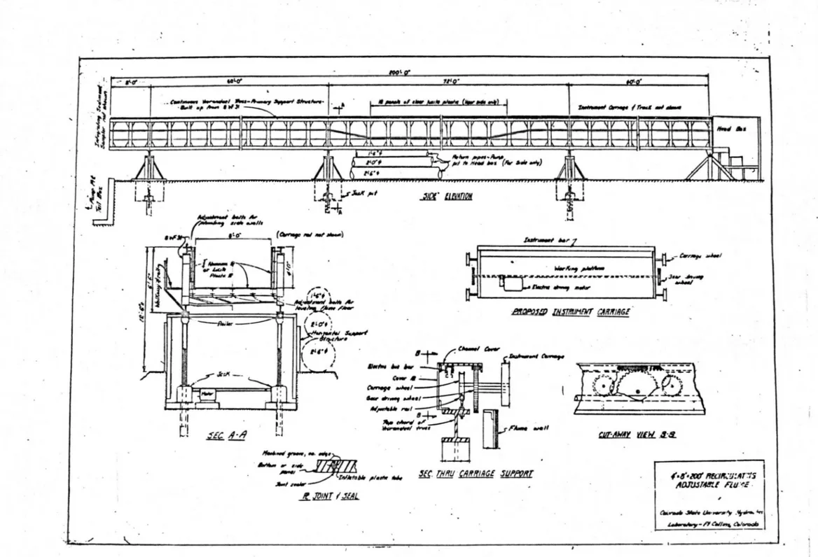
A side elevation of the flume and a few structural details such as built-in adjustable supports !or longitudinal and transverse leveling of the floor and plumbing the walls, the joint sealing arrangement and carriage
support equipment, are shown in Figure t. A general view of the flume is
shown in the backgroW1.d of Figure 2. The interior of the flume, looking downstream, is shO\-vn in Figure 3. A set of 3 multivane diffusers designed for suitable entry of fluid from each of the three recirculating pipes can be seen in Figure 4. The depth and backwater in the flume can be controlled
precisely by means of adjustable fingers provided near the tailgate as shown
in Figure 5. The positive gate shut off to convert the flume to a towing or wave basin and to help control outflow in case of a power failure is shown in
Figure 6. F'igures 7 and 8 show the jacking units. A working and observation
platform is provided all along the flume, a portion of which, near the
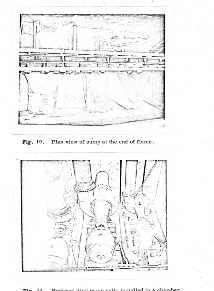
head-box, is shown in Figure 9. The outfall sump is located between the pump
pit and the end of the flume. The outfall sump is designed to avoid sediment storage and to allow air entrained by the jet of water to escape from the water before entering the return pipes and being pumped back to the headbox of the flume. Figure 10 shows the sump during construction and the piping
connecting the sump and the pumps. Three recirculating pumps capable
or
carrying a maximum discharge of 100 cfs are installed in the pit at the end
7
3
Main Features of the Flume:
1. An adjustable slope O percent to 3 percent which can be varied
with the synchronous motor-driven jacking system.
Z. Discharge capacity ranging from O to 100 cfs given by three pumps, a 15 cfs centrifugal pump with variable speed motor, a 35 cfs
centrifugal pump and a 50 cfs axial flow pump.
3. Live-load deflections less than O. O 1 ft for any span under a water
load of 3'-6!1 depth of water in the flume.
4. Fully automatic synchronized-electromechanical jacking units capable of maintainlng true centerline slope of flume to an accuracy o! :!::_ 1/1611 per 200 ft, see Figures 7 and 8.
5 •. -'\n experimental reach 70 ft long, in the middle of the flume, with
transparent lucite plastic walls for observation and photography.
6 • . An instrument carriage with rack and pinion gear drive for
positioning the instruments laterally, vert" cally and longitudinally.
The carriage will be used !or towing purposes and its longitudinal
speed can he precisely controlled between O and 10 fps. PROPOSED EXPERIIVIENTS
With greater world-wide utilization of water resources the importance
of knowledge of river mechanics, channel stability, design of stable chan-nels, sedlmentology and flu vial morphology are of importance for technical
and economic reasons. A greater effort should be devoted to these
signifi-cant areas which, for example, bear on problems of navigation, flood con-trol, flood protection, water supply and water quality. Such studies would
minimize the problem of extrapolating questionable answers to important problems from empirical and semi-empirical relations.
The large flume has been designed to facilitate basic research pertinent
to further development of the theory of the mechanics of flow in alluvial and
Alluvial Channels," No. CEP64H!VS-DBS45 has been proposed to the
National Science Foundation. If funded the study will utilize this facility.
It is proposed to study both analytically and experimentally:
1. the shear distribution on the boundary of channels with different
cross-sections,
2. the ultimate stable cross-section of alluvial channels under
different hydraulic conditions and seclimen4- without sediment inflow based on the variation of shear distribution along the
boun-dary,
3. the effects
of
sediment load, seepage force and flood plainmaterial on the ultimate stable channel cross-section,
4. the application of the results obtained from laboratory studies
to explain the fluvial morpholoflY
ot
rivers,Other priority studies which are planned for the future some of which
were suggested as priority items by the stable channel committee (D. B.
Simons, Chairman) at the ASCE Irrigation and Dra.inage Conference, rvrarch
1064 follow:
I.
Alluvial ChannelsA. Bed Forms in Alluvial Channels and Their Relation to Roughness
and Resistance to Flow --The alluvial channel is unique in that if the bed
material is mobile with flow, bed forms are generated which are related
to
the characteristics of the bed material, the geometry of the channeland the flow. Various bed forms which normally occur in alluvial streams
have been studied in some detail. In general, we can estimate the resistance
!actor if we know the form of the bed roughness. Nevertheless, many facets
of this importan problem remain unanswered. It is essential to more
clearly define the forms of bed roughness which occur in alluvial channels.
It is necessary to deterrnine specifically when certain bed forms will and
will not form. It is equally important to be able to predict the form of bed
5
this ability a refined design of stable channels can not be achieved. Another
facet of this problem which is only generally understood is why the bed .
forms
change as fiow conditions are varied. Hence, we should study thephysical reasons behind the development of the various bed forms, and
why under certain circumstances bed forms such as ripples and dunes vanish
altogether in favor of a plane or flat bed. It is also essential to study the larger, alternating bars which develop and move in alluvial rivers and
canals. In some instances these bars are of such small amplitude it is
difficult to identify them. Under other circumstances these bars may
develop to such an amplitude that they approach the general water surface deflecting the flow back and forth in a meandering pattern around them. The
formation, migration o.nd eradication
or
these large bars significantly affectch,;mnel stability, sediment transport, sorting of the bed material and resis
-tance to flow. and consequently deserve detailed study. Referring to channels whose boundaries are of gravel, cobble or rock, the most common form of
bed roughness recoznized is that associated with the individual grains (grain
roughness). l:<'ield studies have indicated that under favorable circumstances
even these coarse materials can be molded into large bars similar in shape
to dunes. These large bars may affect the resistance to flow in the chan-nels. and at low flows may significantly deflect the main stream in such a manner as to affect channel stability and should be studied.
Bed forms and their relation to roughness and resistance to flow have
been investigated by jnany leading laboratories. In their studiea, the
development of different bed forms was probably hindered by the shallow
-~
water depth of less than one foot. In the new flume, a maximum water
depth o! three to thrcce and one-half feet is available.
B. Sediment Discharge Equations-- 'tany concepts and theories have
been developed to estimate .the magnitude and distribution
or
the suspended6
can provide a satisfactory solution to all flow conditions. Two of the main obstacles are the unpredicability of vertical suspended load distribution and the undefined relationship between the bed load and the suspended load. Studies by Vanoni, Brooks and Chien indicated that the von' Ka.hnori! s-- k1
- 'Value varied with the suspended load concentration. \Vith large flov\' depth avail-able in this new flume, studies should be made in this area to further improve existing concepts. The relative movement of grains of different sizes and their distributions should also be studied with the aid of fluorescent
tracers and radioactively tagged particles.
C.
Turbulence in Open Channels--Thus far i has not been possible to thoroughly investigate the role of turbulence in the mechanics of flow inalluvial channels. With recent advancements in the field of instrumentation,
it
is now possible to proceed in ~'lis field of turbulence using such instru-tnents as the electro-kinetic probe, instruments which utilize the Doppler effect and minute differential pressure transducers specially placed andoriented in probes to measure the turbulence of the flow. Investigations in this area may provide the opportunity to add further refinement to the theories of channel shape, resistance to flow and sediment tran,,port.
Coupled ,with this work the mechanics
or
diffusion should be studied. Flori-metric eHuipment presently available has made it possible to make rapid'
advancements in this area.
D. The Effect of Washload on Stable Channels--In general, washload is the fine sediment transported in the stream. Only small quantities of the washload are found in the bed material and its concentration is essentiatly uniform throughout the flow cross section. Studies thus far indicate that this washload significantly effects channel stability, the development o!
berms and the apparent viscosity
or
the water sedir.:1ent mixture. All facetsof these effects d€serve further attention as well as other possible properties such as rheolo?ical effects of washload.
.,,
.,.
7
To illustrate the importance of washload, with concentrations on
the order of one-hundred thousand parts per million by weight the apparent
viscosity oi the water-washload mixture may be ten times as great as water
alone. This large increase in apparent viscosity apparently reduces the fall velocity of the bed material making it much more susceptible to transport and consequently
it
reacts differently with the now and is molded intodifferent bed forms than prevail for the usual case. perhaps affecting not only resistance to
no
w but
also bed material discharge.Similarly the effect of variations in sediment concentration and size distribution on the transport capacity o! channels and composition of the
channel bed material needs study.
E. The [echanics of the Development of Armor and Utilization of
Armoring in Stable Channels Works--Under some circumstances small
layers of graded coarse material may be used to stabilize the beds and
banks of small channels. In rivers, of moderate depth. coarse material can be used successfully·to stabilize the banks. Field observations have
clearly demonstrated that a small amount of coarse material in a finer
natural material may rapidly develop into an armor as scour and degradation
occur. Available information on bed armor, as o-btafncd in field and labora -tory studies, sh uld be documented in the technical literature. This natural
phenomena. can in som.e situations be of great economic importance and the
principles of armoring with coarse mate;:ials should be studied.
Also, in armored or coarse bed channels the bed material is static
until peak discL arges are experienced which exceed preceding peak dis -charges. These large flows cause transport a..'1d rearrangement of the boun-dary material. The resistance to flow in such channels. changes with
reorientation of the bed and bank material, bank stability and transport
mechanics under such conditions also deserve attention.
F. Predicting Degradation--This problem is closely related to the
.,, ..
8
an otherwise generally fine material may further accumulate as degradation occurs developing an effective armor against further degradation.
Unfor-tunately, even with the presence of small quantities of coarse material
the development of an effective armor can not always be counted upon.
Under certain circumstances of flow the armor developed by degradation
may be effective. Under other flow conditions the armor may be destroyed,
at least temporarily, allowing additional degradation to occur.
It
isessen-tial to develop a better method of predicting the exte_nt to which degradation
will occur and its stability for various conditions encountered practically
in the design and operation of engineering works.
G.
Secondary Circulation in Open Channels--The mechanics ofsecon-dary circulation should be studied in both straight and curved channels. The
secondary circulation should be related to the geometry of the channel which
affects the bed configurations, the sediment transport, the water surface
profiles particularly in the transverse direction. It has long been recognized
that secondary flow around bends in open channels should be studied in detail
along with such factors as energy loss, non-uniform flow, and wave activity.
So far only limited studies have been conducted and most of these have in--volved only rigid channels .
H. Non-Uniform Flow--Most of the sediment research studies have
dealt with uniform now problems. Not enough attention was paid to the
non-uniform flow problem in alluvial channels. Many canals, drawing water from large rivers, can not be designed to carry all the sediment inflmv from
rivers at all times. The study o! flow conditions in the non-uniform head reach
or
a
canal will provide information on the amount of free board required forthe canal to pass a certain discharge, stability and the need for exclusion and/or
ejection works. It will also assist with operation problems and the closure of
dams.
I. Design in Cohesive Materials --One o! the largest voids in design
;;
9
physical and chemical properties predominate in establishing resistance properties, and we do not have instruments or techniques fully developed
for performing comprehensive measurements in the laboratory and field. Present and past methods of describing cohesive materials should be care
-fully reviewed including the plastic index, texture test, chemical compos
i-ti.ons and characteristics of the kind determined in a device such as the
USER shear tank. The possibility of developing shear vanes should be
pursued. Such research could be carried out in the field on both large and
small channels. With the development of a suitable field instrument to
measure shear strength, it is also essential to develop an instrument capable of measuring shear stress on the banks of cohe.3ive channels. Concurrently,
it fa essential to continue the search for parameters or variables which
express the resistance to flow of cohesive banks. Perhaps instruments can
be designed with which bank resistance can be directly measured.
J. Geolo:Yic and Geomorphic Implications --The development
or
astable design for a natural stream must involve some consideration of the
historical pattern under which the existing c annel \Vas created and also
consideration of the probable future influences on the channel. The investi -gations of the geologic and morphologic influences on existing stream systems, and studies in quantitative geomorphology, have been lagging behind until
recent years. These aspects are related to stable channels and deserve
further attention.
n.
Rigid Boundry
ChannelA. Drag Forces on Floating and Submerged Bodies
Different types of objects can be propelled with the carriage. The drag
force between the object and the fluid can be measured by strain gages because the speed of the carriage is controlled.
B. Dispersion Studies--This flume offers large depths, widths, and
10
Different types of tracers can be used. For two-d·meMional studies, the
bottom or the flume can be artificially roughened to limit the boundary layer
growth near the flume walls. With a wave generator, vertical dispersion in
waves can also be studied.
C. -Two Phase Flow-- Fluids of different dens1tites and/or viscosities
can be placed in this flume. Either the top or the bottom fluid can be
re-.- - - circulated at various Sp€eds to study the instability and drag at the. interface.
Due to the large flume depth available velocity distribution in the fluids can
be measured. The towing carriage can be used to propel objects of various shape3 through either of the fluids or along the interface of fluids.
D. Waves--The large flume can find some interesting applications
for
studying the motion of gravity waves due to flow over obstacles, or wavesreflected by structures. The advantage of the large size facility is that waves can be created which are large enough to be unafiected by capillary
action, and still have a wave length small compared with the depth of flow.
The large size also makes possible some particularly interesting
studies of vibrations of structures existed by waves having a frequency
roughly equal to the natural frequency of the structures under investigation.
I
Such problems are difficult to study in a small scale facility because of the
I
difficulties in modeling elastic properties of materials. The structures
contemplated could be stationary structures, such as piers, or moving
structural elements, such as hydrofoils.
E. Translation Waves--The problem of the difference in flow re sis-tance in steady and unsteady flow and its dependence on wave steepness can be
effectively studied in a flume of this magnitude.
The criteria when a gradual wave starts to amplify is also an unsolved
unsteady flow problem, both theoretically and experimentally. The large
flume with available slope up to 3 percent e ables a study to determine the
conditions that exist at the time a gradually varied wave {monocular or solitary) begins to amplify, as well as to determine the rate of attenuation
11
The problem of instability of free surface by wave generation on
the free surface for high velocities is another problem worth studying.
F. Resistance to Flow-- False floor panels covered
with
roughness elements of different form and volume can be easily installed over the flumefioor. With proper instrumentation, detailed investigations o! the sizes of
the zones of separation and their relationship to velocity distribution and to
:/
- ./ I '
,_,.
.
~--,
...
..,_,
.,,,..,
N.,.,,W, _ , 6 ~ "9 ~ . ,~-·
Fig. 1. Schematic drawing of large flume.
_,,
#'•6'•/0D' lfft.1/f,.'!J!IIT-:/S ,t/JJ'J.JT48tf FiU?~E · , "---,,.;.,, u..-') -1t--- ... ~ -flt'WI-a.I-...&---· --- - -- --- - - - -- - -
-Fig. 2. A general view of the flume occupying nearly three-fourths of
the laboratory's entire length. Flow is from right to left.
--- - - --· - - --- - - -' '
..
~<
-·
~~~
,
.:
~7.
~...
. ·,1 'l
Fig. 3. Interior view of the flume ( 8 ft wide) looking downstream toward
.,
---
-Fig. 4. The flume headbox - designed and checked by modeling
-includes three multi-vane diffusers--one for each pump.
- - - -- -- - - · - - - · - --
-Fig. 5. Adjustable fingers at the end of the :f'lume to control depth and backwater in the flume.
I
I I •
Fig. 6. Positive shut off and control tailgate of the flume looking from outside at the outfall end of the flume.
I (.
-.
, ~-) .LI-<
Fig. 7. A pair of one of the three automatic jacking units supporting the flume.
--Fig. 8. A close-up of the jacking unit - synchronized ele
ctro-mechanical equipment.
- - -
---Fig. 9. A portion
or
the flume near the headbox showing the details,··
t
! ~. _. ,r ...~
~~
J
J
f_
.
-
.
-
,_'.
:
~~0~
~
r -
}~. •
~ --.;:--;;:;:--.~
Fig. 10. Plan view of sump at the end of flume.
··" JP .. _ t9 PE .:'!..•;•+ . .-• Uj..--- \ ...
-Fig. it • Recirculating pump units installed in a chamber,
10 feet below the main floor a:::id adjacent to the