Master’s Thesis Mälar dalen University , School of Innov ation, Design and Engineering
Supervisors: Patricia Lag o, Vrije Universiteit Hongyu Pei-Breiv old, ABB Susanne Timsjö, ABB November, 2010
Jenny Jutterström
Innovative User
Interfaces in the
2
Abstract
The goal of this thesis is to explore how the HMI of a process control system can be improved by applying modern interaction technologies. Many new interaction possibilities are arising on the market, while the interaction in the industrial domain still is quite conservative, with computer mouse and keyboard as the central method of interaction. It is believed that by making use of technology available today, the user interface can provide further assistance to the process control operators and improve the effectiveness of the HMI.
A user study was conducted targeting a distributed control system to identify how they work with process control and to find improvement possibilities. The findings of the user study served as input for developing a number of concept ideas. The concept ideas were influenced by user interfaces that use other type of input channels, such as gestures, sound and touch.
A touch-based gesture interface was further explored by developing a concept demonstrator. Finally, the proposed concept was evaluated by a usability test. The concept demonstrator will be continued developed at ABB and other purposed concepts will serve as input to potential future projects.
3
Table of content
1 Introduction ... 5 1.1 Purpose ... 5 1.2 Delimitations ... 5 1.3 Thesis outline... 6Definitions and acronyms ... 6
2 Theory ... 7
2.1 Distributed control system ... 7
2.1.1 HMI background ... 7
2.1.2 HMI Guidelines ... 8
2.2 Innovative user interfaces ... 11
2.2.1 Attentive user interface... 11
2.2.2 Auditory interface... 13
2.2.3 Free form gesture interface ... 15
2.2.4 Haptic interface ... 18 2.2.5 Tangible interface ... 20 3 Method ... 22 3.1 User study ... 22 3.2 Market scan ... 22 3.3 Design concepts ... 22 3.4 Concept demonstrator ... 23 3.4.1 Competitor analysis ... 23 3.4.2 Design phase... 23 3.4.3 Implementation phase ... 23
3.4.4 Usability testing phase ... 24
4 Results ... 25 4.1 User study ... 25 4.1.1 Background ... 25 4.1.2 Interview questions ... 25 4.1.3 Raw data ... 27 4.1.4 Extracted requirements ... 28
4.1.5 Findings from the user study ... 29
4
4.3 Concept demonstrator ... 31
4.3.1 Competitor analysis ... 31
4.3.2 Design ... 31
4.3.3 Implementation ... 32
4.3.4 Concept Demonstrator overview ... 36
4.3.5 Validation... 37
5 Conclusions ... 38
6 Future work ... 39
5
1 INTRODUCTION
This master thesis was conducted at ABB Corporate Research in Västerås, Sweden together with Yuan Yao, master student at the Royal Institute of Technology in Stockholm. The thesis work was carried out with the target to improve the effectiveness of the operators when using a distributed control system (DCS) The DCS provides operators real-time control and monitoring of industrial processes and is today used in a variety of domains, such as biotechnology, petrochemical, pharmaceutical, pulp and paper, mining, food and beverage.
One important component to achieve high operational effectiveness is the human machine interface (HMI). The HMI must assist an operator when handling an abnormal situation and facilitate awareness of the current process state. Today, a traditional user interface is used with keyboard and mouse as the main interaction method. But many new interaction technologies are arising on the market and new types of interfaces are emerging. This thesis aims to explore if and how the operator effectiveness can be improved by applying interaction technologies available today.
1.1 Purpose
The purpose of this thesis is to investigate how user interfaces that use other types of interaction channels, such as touch, sound and gestures, can be applied in the process control environment to improve the user effectiveness of DCS systems. In order to achieve this goal, some beginning tasks and questions must be answered which also formulate the project outline.
How to design effective HMIs for industrial plant operators? What types of interfaces are available today? Typical applications? How to take advantage of modern UIs for process control?
1.2 Delimitations
The outcomes of the thesis project are concept ideas targeting identified issues when using distributed control system and a working prototype showing a proposed solution. Since the UI domain contains numerous types of interfaces, only a subset will be discussed in this thesis. The selection was made based on discussions within the project team. Furthermore, the user study conducted in this thesis resulted in a number of user requirements. Not all requirements were covered in the presented concept ideas due to the time limitations of this work.
6
1.3 Thesis outline
Chapter 1 (Introduction) explains the purpose and objective for this thesis. Chapter 2 (Theory) provides background knowledge of distributed control
systems, an overview of HMI guidelines process control and an introduction to the types of user interfaces considered in this thesis.
Chapter 3 (Method) describes the methodology adopted to carry out this
thesis and the process of the project.
Chapter 4 (Results) presents details about the results of the user study, the
proposed concept ideas and the implementation of the concept demonstrator.
Chapter 5 (Conclusions) concludes the results made in this thesis.
Chapter 6 (Future work) suggests improvements of the proposed solution and
open up topics for future research.
Definitions and acronyms
Term/Acronym Description
DCS Distributed control system. HMI Human machine interface. GUI Graphical user interface.
MVVM Model-View-ViewModel design pattern. NUI Natural user interface.
7
2 THEORY
2.1 Distributed control system
Distributed control systems are systems designed for controlling manufacturing processes, such as oil refineries, pharmaceuticals production, and power plants. The term distributed refers to the location of the controllers, which are not grouped at a central point, but geographically situated throughout the system controlled by the DCS. The controllers automatically adjust the process output by examining received information from I/O modules connected to the process equipment, such as switches, vaults and pumps. The regulations are made based on stated conditions regarding pressure information, temperature records, fluid level, and so forth. Therefore, not all regulations have to be performed manually, but the ability to configure the process conditions must be easily supplied by the systems HMI to ensure process safety and quality.
The distributed controllers are connected to the HMI through a central controller. The HMI essentially presents the process data and current states to the operator and allows the operator to perform plant operations or override automatic settings when required.
2.1.1 HMI background
The earliest HMI were designed for control rooms at manufacturing plants in the 1930s-1940s. The HMI consisted of panels positioned on the walls and the control room was often located close to the actual plant process. It was common to reflect the layout of the process by creating graphical representations of the plant process as the panel background, and place the panels in their corresponding positions (Hollified, Nimmo, Oliver, & Habibi, 2008).
This approach continued into the 1960s when electronic instruments were integrated with the old pneumatic instruments in the panels. One advantage with the wall design was the immediate overview of the process condition, the information was always visible and the state of the process could be identified by experience operators by looking for patterns in the panels. The presented information had been carefully selected, because of the expense to add new panels which may require moving others to preserve the logical arrangement. In the 1980s, the physical instruments began to be replaced with software displays. The technology then was expensive, but the software allowed for much easier and cheaper configuration of the structure. However, the digital displays on CRC monitors limited the overview of the process and resulted in the practice to configure alarms for process conditions, which later gave rise to alarm management problems. The upcoming ability to change the look of process graphics increased the customizability. However, at the time, not
8 much research had been performed on process graphic design and the process graphics was often not consistent or properly implemented.
CENSORED BY ABB CORPORATE RESEARCH.
2.1.2 HMI Guidelines
The HMI is not only an important factor to enable the operator to work effectively, poorly designed HMIs have been cited as contributing factors to industrial accidents and also showed to degrade safety, quality and profitability. Therefore, guidelines for designing HMIs for control operators in industrial environments have evolved. This chapter gives a brief overview of guidelines proposed by (Hollified, Nimmo, Oliver, & Habibi, 2008) and (Bullemer, Reising, Burns, Hajdukiewicz, & Andrzejewski, 2009) which will be kept in mind in the continued work.
2.1.2.1 Process situation awareness
During abnormal situations, the operating team in the control room needs continuous situation awareness, which is defined as a correct and timely understanding of the state and behavior of the process. This knowledge must be attained with minimal distractions of the operators in their work. In the past, this was realized by using the control room walls, where experienced operators and engineers could recognize signal patterns in the displays and thereby deduce the current situation. To apply this solution in modern control rooms, it is recommended to supply a large process overview, with relevant information that support the situation awareness and facilitates discussions. In this manner, the operating team can easily see the current status of the plant, without interrupting operators with questions or requests.
2.1.2.2 Process display hierarchy
To avoid cluttered graphical displays, which often contain a static amount of information independent of the operation context; it is recommended to design graphical displays with progressive exposure of information. For example, during abnormal situations, it is likely not the same type of information that is needed as when running the process in normal conditions. This should be addressed by the HMI to better support operators through upset situations. By designing process displays containing different levels of detail, the information presented in the graphic display will better suit various needs of the operators. The following display structure is recommended, which proposes a hierarchy, where the operator can “zoom in” the process by going through the levels of detail. The overview displays are placed at the top levels and displays with high-detail information in the bottom levels.
Level 1: Process overview displays, used for situation awareness. Level 2: Process unit control displays, used for process manipulation.
9 Level 3: Process unit detail displays, used for detailed examination. Level 4: Process unit diagnostics display, used for troubleshooting. The main purpose of arranging the graphic displays in a hierarchy is to filter the amount of information. However, the process graphic hierarchy may also support the navigation by contributing to the orientation awareness when navigating in the system.
2.1.2.3 Process display design
It has been shown that improper design and poor information presentation prevent the operators from recognizing important information and to distinguish process conditions, thereby contributing to increased response times. The following HMI design recommendations are stated to enhance important information.
Colors: Gray background colors reduce the risk of glare. In general, colors should be very restrictedly used and any alarm color code must only be used for displaying alarms.
Navigation: All process displays should be accessed through minimal actions and the methods of navigation must be consistent.
Animation: Animations should not be misused; generally it is only appropriate to be used for highlighting abnormal situations.
Display elements: Must have consistent look and color in all display contexts. All process equipment should be displayed in 2D.
Process layout: The process presentation should correspond to the operators’ mental model of the process, e.g. conform to the physical plant arrangement. Furthermore, the process should flow from the left side to the right, with gas flowing up and liquid down.
2.1.2.4 Navigation
The HMI should provide multiple ways of navigation and should not require the operator to type in titles of the items to access. Furthermore, the system should not demand the user to know the graphic display hierarchy on advance. One solution is to provide a navigation menu with short cut access to all included process graphics.
The navigation methods should support the operator when navigating up and down in the display hierarchy, but also sidewise in the hierarchy levels and promote easy access to related details and trends. If the system provides dedicated shortcut keys on a keyboard to open process displays, these should be arranged so that they map the defined display hierarchy. The level 2 displays are generally considered to have the highest importance; therefore these displays should be given dedicated keys if the key space is limited.
10
2.1.2.5 Operator workstation
The design of the operator workplace is important to ensure operator alertness and contribute to situation awareness. It is recommended that each operator workplace contain four screens and one overview display to operate effectively. Even though more screens are often requested, it has been shown that the extra screens are not used or only presents redundant information. The operator workplace is often used by one person; however, during training or special circumstances, the workplace can be operated by more than one person and should therefore include more than one keyboard.
The arrangement of the screens should minimize the risk of neck strain injuries. Therefore, a horizontal layout is preferred. However, the horizontal arrangement makes it difficult to observe the information presented on all screens.
11
2.2 Innovative user interfaces
In this thesis, four types of interfaces have been considered when creating the concept ideas presented in chapter 4. This chapter gives a brief introduction to these interfaces with typical application domains, in order to get a better understanding of the interface and inspiration for developing concepts ideas.
2.2.1 Attentive user interface
Attentive user interfaces (AUI) are interfaces that take the users’ attention into account to avoid interruptions and to assist the user with relevant information. One example of bad design considering the user attention is unexpected pop-up windows that are automatically displayed when entering a webpage. This implementation does not support the users’ current focus and is often experienced as an annoying interruption. This consideration of current task and focus can be further elaborated, to not only include a single device. Today, we are commonly being surrounded by multiple computing devices and (Vertegaal, Shell, Chen, & Mamuji, 2006) has proposed the following properties, as a framework for realizing an AUI environment.
First, the UI should determine what device the user is currently using and what kind of task that is being performed. This could be determined by for example, identifying eye fixations, the body position and the proximity from the device. This information should then be distributed to enable other devices to take into account if the user is available for communication or not. In order to make the decision of making an interruption, the behavior of the user should be modeled, e.g. based on statistics, from which task prioritization can be estimated. The interface should then determine if the user is available for interruption by comparing the task priorities or require an acknowledgement from the user before carry through the interruption. Furthermore, the user attention should be generally augmented by the interface and, for instance, magnify information of interest, while details can be peripheral.
12
2.2.1.1 Applications
One application of AUIs is to organize windows according to the users’ visual focus. EyeWindows is one example of an implementation that arranges the desktop windows by considering information received from eye-tracking technology. The position and size of the windows are adjusted depending on where the user currently is looking, see Figure 1. A study has shown that the time to focus a specific window by using eye-tracking is about two times faster than when using a computer mouse or shortcut keys on the keyboard (Fono & Vertegaal).
Figure 1: The desktop windows are automatically being resized and positioned depending on the users’ eye fixation.
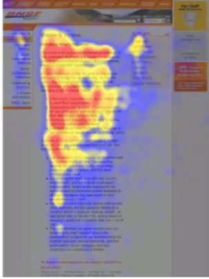
AUIs are today commonly used in usability testing to accommodate the users’ interest. Eye-tracking is often applied as a way to record the users’ visual behavior while performing a number of tasks. The received information is afterwards investigated to determine what contents in the GUI that gets the most user focus, where the user is looking for particular information and what elements that causes confusion. Figure 2 shows one example of a heat map, generated from the amount of visual focus. Besides for indentifying usability issues, the recorded information can also be used for designing and publishing branding and advertisements.
13
2.2.2 Auditory interface
Most interfaces rely on visually presented information alone. The use of auditory interfaces in human computer interaction is often limited to signals for indicating warnings or notifications, such as alarms, low battery alerts or incoming messages. However, in the everyday life, sound and vision usually complements each other. Vision provides information about size, color and shapes of objects, while sound gives an understanding about their interior. In the same way, spoken words are capable of expressing properties that are absent in write, hence its central role in human communication. It is therefore believed that sound interface can be a powerful complement for conveying information.
One advantage with an auditory interface is the reduced load on the visual attention, which allows the user to focus somewhere else during the interaction. For example, be able to start an application by using a voice-controlled system, while performing some other task simultaneously. Furthermore, in cases were no visual presentation is needed, the device gets less size-demanding which can be convenient. The portable interaction style may also contribute to ergonomic properties, by not requiring a fixed working position. But the users’ environment is very important, since auditory interfaces usually not are suitable in noisy or silent obligated surroundings.
2.2.2.1 Applications
Auditory interfaces have for a long time played an important role in computer games, for notifications about events happening in the game world and to get the users’ attention. Audio can for instance be used for illustrating the need to change gear in a racing game, or to make the user aware of an approaching game character by adding the sound of footsteps. Within the game domain, it is also recommended to use audio feedback as a complement to the visual presentation of the graphical user interface (Adams, 2006), such as audio confirmations when pressing buttons and so forth. Sound is also promoted as a way to enhance the current game mood to the user, by using music, in the same way as in movies.
Another typical application domain is command systems. A speech-command system generally consists of three parts; understanding the input, decide what action to perform and generate an output to the user. This can be an effective way for the user to express a specific request, such as making a ticket reservation by phone. Because the auditory interface does not require the users visual attention, these systems have gained popularity in situations that require a high level of visual attention, e.g. in case of driving a car. However, distributing information by speech is generally slow and attention demanding. The quality of speech-command systems is also difficult to ensure, due to the difficulty to predict all possible scenarios (Gärdenfors, 2001).
14 Auditory interfaces are also being applied for multimodal spoken dialogue systems (MSDS). MSDS is a speech-command system which combines an auditory interface with a graphic avatar, commonly a talking head, which imitates a face-to-face communication. The goal is to make the interaction more natural to the user by adding emotional expressions, such as a smile or raised eyebrows to the communication. One example of a MSDS is AdApt (Gustafson, 2002), which is an information system that allows the user to browse available apartments with the help of an animated agent, to whom the user is able to ask questions (Figure 3).
Figure 3: Multimodal system helps the user to find available apartments, by combining an auditory and visual interface.
15
2.2.3 Free form gesture interface
The technology industry, in particular the gaming and consumer electronics sector, has started to unfold technologies which obviate the need of using an input device when interacting applications. Instead, the user is able to control the television, cell phone or computer by only using their hands, while software interprets the movements in real time. This expanding interaction field, where users do not need to wear special clothing nor use a device, is called free form gesture interfaces (GI), and classified as a type of natural user interface (NUI).
Previous attempts for realizing natural user interfaces have often been considered ineffective and imprecise, mainly because the technology relied on standard cameras that only allowed a 2D perspective. The main step forward of the technology used today is the capability to observe the world in three dimensions, allowing more complicated gestures (Saffer, 2008). This also enables the software to better cope with difficulties such as differentiate commands and detect distances.
Gesture interfaces enables systems to take advantage of users’ pre-knowledge from interactions with non-digital artifacts, by using gestures that already are familiar to the user. This can facilitate the learnability (Robert, Girounard, Hirshfield, & Horn, 2008). Furthermore, GIs encourages body movements and may therefore contribute to ergonomic qualities. Another benefit with gesture interfaces is the absence of a device; the interface enables the user to directly execute a desired task, without having to perform sub-tasks to reach the goal. But the absence of a device brings the deficiency of affordances, properties of an object that indicate of how to interact with it, which adds the difficulty on how to enable the user to discover that a natural user gesture interface exists in the environment, and to intuitively know how to interact with it. The use of body motions can also be physically demanding, which therefore may decrease the accessibility for people with reduced mobility.
2.2.3.1 Applications
The field of gesture recognition has found applications in various domains. Within the robot and human interaction area, research has been performed to enable hand gestures for robot control, as a way to make the communication more intuitive for the user (Wang, 2008).
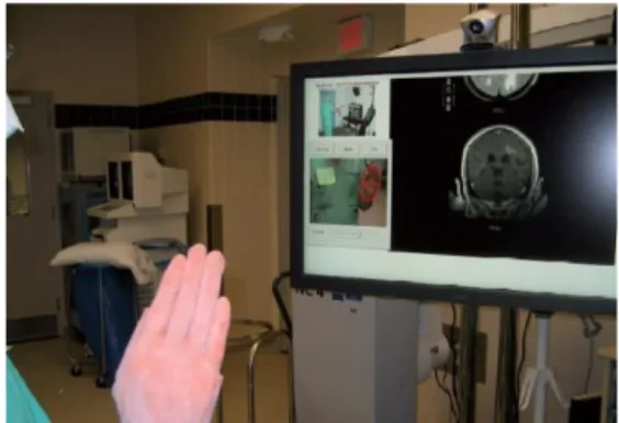
Gesture interfaces are also being applied for desktop computer interaction. One example were this is useful is within the medical field, for devices in sterile environments. Today, touch screens are for example being used in hospitals, which must be frequently cleaned to avoid contamination to be spread. By using gestures instead, both the hands and the device remain sterile when used. Gestix is one example of a gesture recognition system which interprets hand gestures in real time for medical applications (Wachs,
16 o.a., 2008). The users are able to browse and interact with images during a surgery by only using their hands, see Figure 4.
Figure 4: Using hand gestures to navigate images during a brain surgery.
Gestures are also being used for physical therapy and rehabilitation training. SilverFit (SilverFit BV Alphen) has developed computer games which in combination with gesture recognition technology, makes it possible to help disabled persons to maintain their physical therapy. The application provides exercises which are prescribed in rehabilitation for medical incidents and then gives live feedback to users by recognizing their body movements during practice.
Figure 5: Rehabilitation training, the patient walks around to pick flowers and gets live feedback by gesture recognition.
Within the consumer electronics domain, gesture interfaces are for example being applied for interaction with televisions, small devices and computer applications. Hitatchi is expecting to release a gesture controlled television at the end of 2010. The television includes a 3D sensor, which allows the user to for example, swipe a hand sideways to navigate through channels. The technology is also able to recognize people and thereby adjust the contents depending on who is currently watching.
Another area of application is interaction with small devices, which is one of today’s interaction challenges. Conventional input methods, such as keys or touch screens, requires sufficient of space to be effectively used. Abracadabra
17 (Harrison & Hudson, 2009) is an example of a finger input technique that tries to solve this problem by extending the input area to cover the space around the device. This makes the user able to navigate and use buttons by interacting with abstract representations next to the device (see Figure 6). Cell phone companies are also developing gesture interfaces as a way to interact with phones, for example, adding features to answer a call or adjusting the speaker volume by moving the hand in specified motion patterns next to the phone (Nokia, 2010).
Figure 6: The user moves the cursor by moving the finger next to the device and access abstract buttons placed outside of the screen by tapping in the air.
18
2.2.4 Haptic interface
Haptics refers to the sense of touch and haptic interfaces aims to make use of the humans’ sense of touch during computer interaction. This field is generally divided into two categories, tactile feedback and kinesthetic feedback. Tactile feedback provides information to the user by giving indications to the nerve endings in the skin, such as heat or the sensation of a texture when touching on a surface. Kinesthetic feedback mimics the feeling of a pressure being applied, e.g. a centrifugal force when rotating a virtual object. The combination of tactile and kinesthetic feedback is called force feedback.
Haptic technology has made it possibility to examine how the human sense of touch works. The ability to generate three-dimensional force feedback has also added an additional aspect to the user experience in computer generated environments. By using vibrations, forces and motions as stimulus, the user is able to feel mechanical properties of virtual objects, such as their weight, surface and shape. This allows simulating interactions with real objects, but also the possibility to experience virtual objects with properties that normally are impossible.
2.2.4.1 Applications
Haptic interfaces are today employed in the consumer, scientific and industrial sector. In the consumer sector, haptic feedback is for example incorporated in the gaming industry. Another application domain is virtual control panels, which usually does not give the user any tactile feedback during interaction. Research has shown that by allowing the user to feel confirming responses such as depress and release of digital buttons, the number of input errors are reduced and the input speed is increased (Brewster, Crohan, & Brown, 2008). Furthermore, tactile response can also be useful in environments where visual and sound feedback is not enough, such as when interacting with a device while it is placed in a pocket or when the users’ visual attention is somewhere else, e.g. touch screens placed in vehicle interiors.
Within the scientific and industrial field, force feedback is being used for training purposes, to allow the user to obtain skills learned by feeling and repetitive practice. This is a desirable aspect in medical training, where the sense of touch is essential. The virtual training makes it for example possible to practice a surgery in order to gain confidence and experience before making the real inception (see Figure 7). Force feedback is also being incorporated in teleoperations; to control space exploration vehicles and maneuvering undersea salvage devices from remote locations.
19 Figure 7: Surgery practice by using two Phantom haptic devices that imitates the feeling of performing a real surgery.
20
2.2.5 Tangible interface
A tangible user interface (TUI) is an interface that enables the user to interact with digital information through the physical environment. The traditional WIMP structure, where the user can interact with windows, icons and menus, can in some cases limit the expressive capabilities to six actions; select, position, orient, path, quantify and text (Foley, Wallace, & Chan, 1984). TUI aims to instead integrate the interactions to the physical world, to enable more and varied actions. TUI can be defined as interfaces which “give physical form to digital information, employing physical artifacts both as representations and controls for computational media” (Ishii & Brygg, 2001), which means the input and output devices should fall together. Figure 8 shows a simple example of the difference between WIMP and TUI on a touch screen, which falls under WIMP because the information is not physically graspable, but by adding interactive physical objects to the surface, the UI becomes tangible (Hancock, Hilliges, Collins, Dominikus, & Carpendale, 2009).
Figure 8: Using tangible (left) and touch (right) input to interact with menus.
One benefit with TUIs is the ability to take advantage of skills learned from interacting with the physical environment. The UI can make computing more invisible and intuitive by embodying the information in objects that users are familiar with, such as tables, pens and toys. Because tangible object often are portable, this UI can also contribute to ergonomic properties, by not requiring a fixed position, as traditional mouse and keyboard. However, tangible objects can generally not be easily added or modified, compared to a visual presentation only, which may limit the versatility of the UI.
2.2.5.1 Applications
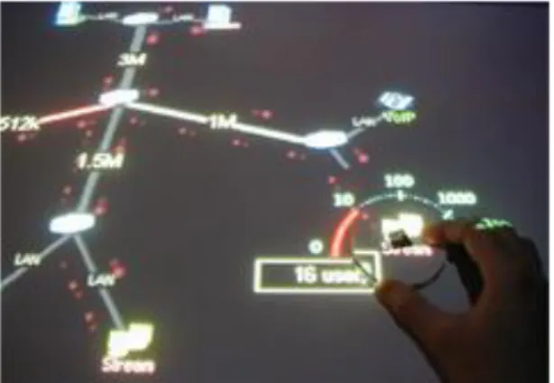
One widespread application area of TUIs is to enhance the interactions of interactive tables. An example is the Augmented Urban Planning System, which is a workbench for urban planning (Underkoffler & Hiroshi, 1999). The user can put physical architectural models on a surface, which generates virtual shadows according to a specified time of the day and season. By rotating a physical control, the virtual clock is changed and the model shows how shadows and reflections are being correspondently adjusted. Another
21 example is the application IP Network simulation (Kobayashi & Mitsunori, 2003), which allows users to configure a network, set node parameters and create links by using physical objects on a table, see Figure 9.
TUI is also being applied for toys. Topobo has released a construction set (see Figure 10) which enables the user to build creatures by using blocks in a similar way as LEGO, but each block has kinetic memory. This makes it possible for each part to record and playback physical motions, which enables the user to teach the object to walk or dance by only moving the blocks.
Figure 9: The user is able to change settings of a network by using tangible object placed on the surface.
22
3 METHOD
3.1 User study
In order to get a better understanding of the user context, a user study was conducted. The user study was performed by interviewing two process control operators and through direct observation when they were using a distributed control system. All received information was used to determine issues to identify user requirements. However, due to the time constrains of this work, only some of the findings made in the user study were selected for further investigation. The selection was based on the ability to be solved by applying new interaction technologies.
3.2 Market scan
To get inspiration before the development of design concepts and gain knowledge about what interaction technologies that is available today and what interaction devices that are arising on the HCI market, a market scan was conducted. The market scan was performed in the haptic, gesture, sound, attentive and tangible interface domains. Each domain was documented with examples of typical applications and technologies used for the interaction.
3.3 Design concepts
The design concepts were generated by brainstorming sessions inspired by the method called brain writing. Brain writing is a creativity technique used for rapidly produce product ideas. In contrast to regular brainstorming, the participants are asked to write down any ideas of a topic within a short time frame. It is not the quality of the ideas that matters, but the quantity. Afterwards, all ideas are discussed and one advantage with this approach is the visibility of the generated ideas, they can easily be examined later for further elaboration or to trigger additional ideas (Wilson, 2006)
23
3.4 Concept demonstrator
3.4.1 Competitor analysis
Before starting the development of the concept demonstrator, a patent search was conducted to determine if any competitor had been granted patents in the area. The patent searches were performed in international patent databases, and the search strings was formulated with assistance of a patent specialist employed by ABB.
3.4.2 Design phase
The design phase consists of defining use cases and the process of throw-away prototyping. The use cases were selected based on discussions within the project team, with the goal to target the most common tasks for process control.
After preliminary use cases had been defined, throw-away prototypes were created to refine the use cases before the implementation. Throw-away prototypes are used to visually show how use cases may look like when the system has been implemented, by creating simple models of system parts. One advantage of throw-away prototyping is the possibility to early get feedback about the GUI layout and how the use cases will be implemented, while the system still can be easily modified before the implementation. Furthermore, throw-away prototypes are also useful as a visual specification of the user interface during the development process.
The method chosen for creating throw-away prototypes was paper prototypes, because of the time constrains. By using paper prototypes, low-fidelity prototypes can be quickly generated by using papers, sketches and post-its.
3.4.3 Implementation phase
The implementation phase begun by deciding the hardware platform, the software platform, defining the system architecture and which development tools to use. The hardware was selected based on a market scan of available technology, within a defined price range. Windows 7 and .Net framework 4 was decided as the software platform, because of its enhanced multi-touch support. The concept demonstrator was decided to employ the Model-View-ViewModel pattern (MVVM), which is a design pattern developed for .Net applications by Microsoft.
24 To ensure easy integration, the development method was influence by Scrum, which encourages communication among small development teams and close communication with the product owner, in this case, the project team. Every morning, a meeting was conducted that followed the guidelines of “Daily scrum”, covering last day’s progress, plans for today and any issues for completing the defined goals.
3.4.4 Usability testing phase
The purpose of the usability testing is to evaluate the concept demonstrator by observing subjects using the product to perform realistic tasks (Rubin, 1994). The goal is to indentify usability deficiencies which affect the performance and accuracy for completing the tasks. The feedback of the usability test will be input to the future development to improve the usability and minimize the user frustration when using the product.
The think-aloud protocol was chosen to gather data during the usability tests. This method encourage the subjects to talk aloud as they are performing tasks, describing what they are looking for, what they expect an action will do, what they are doing or feeling, at the same time as they perform predefined tasks. The tests were observed by two persons that made notes during the test and encourage the subjects to communicate their thoughts.
The subjects participating in the usability test were employees and thesis workers at ABB Corporate Research. Most subjects have some experience in HCI and software development, and are familiar with distributed control systems.
25
4 RESULTS
4.1 User study
This chapter begins by introducing the background of the user study, afterwards the interview questions are presented, together with the data that were retrieved during the user study and the extracted user requirements. The final section presents findings identified as related to the HMI.
4.1.1 Background
The CHP plant is operated in three shifts, with 11 people located in the control room during each shift. At a shift hand over, the shift teams communicates the current status of the plant and how much heat and electricity that is expected to be needed on the following shifts.
The control room contains three operator workstations which are placed in front of a large process overview screen that covers one of the walls. The room also contains work desks for other types of shift team personnel, e.g. shift manager, and a conference table is placed in the middle. There are no windows in the room, but a number of monitors show real-time videos from several cameras placed in the plant.
The user study was performed on a morning shift by interviewing two of the operators and through direct observation when they were using the system. During the user study, an abnormal situation occurred which contributed to information on how the operators cope with stress and how the work environment is affected.
4.1.2 Interview questions
Before the user study was conducted, a number of interview questions were prepared. The questions were influenced by recommendations found in the HMI handbook (Hollified, B.) regarding field studies. All questions can be found in Table 1. The provided answers are presented in next section.
26 Table 1: Interview questions for the user study.
Operator experience
How many years have you worked as an operator? Education?
Workflow
What is the first thing you do when you come to your operator workplace? Explain how you configure and set up the operator environment?
Are some displays always visible? If so, which ones?
What functionality do you use most in the control system? Why? Is there any functionality you are aware of but never use? Which?
Is there any information presented in the operator workplace you find particularly useful/irrelevant? Why?
What functions in the control system do you feel is the most difficult to use? Why? What do you do when an alarm occurs?
Can you show how you change an object parameter?
How do you turn over the operator workplace to the next operator? Is there much collaboration between the operators? If so, how?
Operator workplace
Do you use all available screens? For which purpose? Do you feel comfortable when you are using the system? How do you usually navigate in the system?
How do you communicate from the operator workplace with the field engineers? Any suggestions on how to improve the interaction with the system?
27
4.1.3 Raw data
28
4.1.4 Extracted requirements
29
4.1.5 Findings from the user study
30
4.2 Design concepts
31
4.3 Concept demonstrator
CENSORED BY ABB CORPORATE RESEARCH.
4.3.1 Competitor analysis
CENSORED BY ABB CORPORATE RESEARCH.
4.3.2 Design
CENSORED BY ABB CORPORATE RESEARCH.
4.3.2.1 Use cases
CENSORED BY ABB CORPORATE RESEARCH.
4.3.2.2 Low-fidelity prototype
32
4.3.3 Implementation
4.3.3.1 Hardware platform
33
4.3.3.2 Software platform
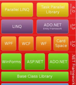
The demonstrator is based on Microsoft .Net framework 4.0. The .Net framework is intended to be used for applications created for the Windows platform and is installed by default of Windows Vista/7. The framework contains libraries for building and running .Net applications, and all technologies provided by the framework is shown in Figure 11. The reason for selecting this framework for the concept demonstrator was because of the enhanced multi-touch support in user interfaces created by Windows Presentation Foundation (WPF), included in .Net framework 4.0.
Figure 11: The .Net Framework stack.
4.3.3.2.1 Windows presentation foundation
WPF is a framework for developing and rendering graphical user interfaces for stand-alone and browser-hosted applications. The created interfaces are vector-based and therefore resolution independent. The engine used for rendering the UI employs the graphic hardware of the computer, which makes it possible to include more advanced contents to the user interfaces, such as 3D-graphics and animations. Another benefit with WPF is the powerful data binding. WPF introduces dependency properties, which are properties that computes their values based on values of other inputs during runtime. This makes it possible to for example, easily bind various UI control properties to common language runtime (CLR) properties of objects existing in the business logic, by exposing their values as dependency properties.
WPF attempts to make a clear separation between the UI and the business logic, to facilitate concurrent development. Microsoft has therefore developed a declarative XML-based UI language called Extensible Application Markup
34 Language (XAML). XAML is used to define and structure the UI elements, similar to how HTML is used for web pages. Everything implemented in XAML can be expressed in C#/VB. However, XAML has its advantages and most importantly, it contributes to separate the UI and the business logic in the code behind.
The included UI controls have a number of built-in events, which automatically invokes any listener when the event is raised. Typical events are button presses and text entries in input boxes. As mentioned before, WPF respond to touch input and in the latest version, .Net 4.0, the UI element base class also exposes touch events such as touch-down, touch-up and touch manipulation.
4.3.3.3 Software architecture
35
4.3.3.3.1 Communication
The concept demonstrator employs WCF for communication between the components. WCF is an interface provided by the .Net framework for building service-oriented applications. The interface allows the applications to host several services which can be used by multiple clients, and every client can consume multiple services. The services are implemented by using the Web Services Description Language (WSDL), which is a XML-based language that is used for describing the services. The interface allows you to for example, specify the endpoint of the service and define the provided operations by operation contracts (similar to function calls in traditional programming). WCF also allows services to implement callback contracts, which enables the service to push information to the clients. In this way, the clients do not need to poll the service to get updated information, instead all clients automatically gets notified. The table below gives an overview of the services implemented in the concept demonstrator.
CENSORED BY ABB CORPORATE RESEARCH.
4.3.3.3.2 Model-View-ViewModel pattern
The concept demonstrator application follows the Model-View-ViewModel (MVVM) design pattern. MVVM was developed by Microsoft to facilitate the separation of GUI development from the rest of the implementation. One purpose of this separation was to enable interaction designers to develop the GUI only by using XAML, simultaneously as other developers can work on the business logic concurrently, without interfering with each other. The MVVM pattern is based on the Model-view-controller (MVC) pattern, but in addition to the separation between view and the logic, MVVM is design to make better use of specific WPF functions, such as data binding and to minimize or eliminate the need for “code behind” in UI layer classes.
The MVVM pattern includes the following types of elements:
Model: Refers to a CLR object and like when using MVC, the model should not be aware of it is being used in a view or not.
View: Refers to an element displayed in the GUI, such as windows, lists, and other types of controls.
ViewModel: The layer between a model and its view; used for exposing properties from the model to the view, available commands and abstractions.
36
4.3.4 Concept Demonstrator overview
37
4.3.5 Validation
The validation was performed with the goal to determine if the defined use cases can be successfully and effectively accomplished by a user with no earlier experience of the concept demonstrator. Therefore, a usability test was performed with the aim to discover issues when using the concept demonstrator, and also to identify improvement areas. This information is in particular valuable for the continued development of the concept demonstrator at ABB. Because of the time limitation, the test could not be performed with actual operators. However, all four test subjects were personell with some knowledge about DCS systems.
Besides testing the usability of the concept demonstrator, properties such as performance of completing a task, e.g. how many steps were required to complete a task and if the subject appear confident when using the touch-based interaction will be considered.
Before the test was started, the subject was informed about the think-aloud protocol and the purpose of the test; not to test the subject, but the instructions and the path for completing a task. The subject also performed a warm-up exercise before the test begun, to get a bit familiar with the test procedure before the actual test. The test consisted of three types of tasks; navigating graphical aspects, system alarm management and operating process objects.
4.3.5.1 Result
CENSORED BY ABB CORPORATE RESEARCH.
4.3.5.2 Summary and conclusions
38
5 CONCLUSIONS
This thesis was carried out to investigate if the UI of a DCS can benefit by applying new human-computer interaction technologies. Today, it is commonly based on a traditional user interface with keyboards and computer mice as input devices and monitors as output devices. However, many new HCI techniques are appearing on the market, which makes use of different interaction channels, such as touch, sound and gestures. This has opened up opportunities for creating more advanced UIs to further enhance usability and user effectiveness. The UIs and design concepts explored in this thesis shows that by applying other types of interfaces, in contrast to using a traditional UI alone, the system can bring further support to the operators’ attention.
39
6 FUTURE WORK
40
7 REFERENCES
Adams, E. (2006). Fundamentals of Game Design.
Apple. (2010). Apple. Retrieved August 2010, from http://www.apple.com/magictrackpad/ Brewster, S., Crohan, F., & Brown, L. (2008). Tactile Feedback for Mobile Interactions. CHI'08. Bullemer, P., Reising, D., Burns, C., Hajdukiewicz, J., & Andrzejewski, J. (2009). Effective Operator Display Design: Asm Consortium Guideline. CreateSpace.
Foley, J. D., Wallace, V., & Chan, P. (1984). The Human Factors of Computer Graphics Interaction Techniques. IEEE Computer Graphics .
Fono, D., & Vertegaal, R. (2006). EyeWindows: Evaluation of Eye-Controlled Zooming Windows for Focus Selection. HCI'06.
Fono, D., & Vertegaal, R. (2005). EyeWindows: Using Eye-Controlled Zooming Windows for Focus Selection. CHI'05.
Gärdenfors, D. (2001). Auditory Interfaces, a Design Platform.
Gustafson, J. (2002). Developing Multimodal Spoken Dialogue Systems - Empirical Studies of Spoken Human-Computer Interactions. Trita-TMH (2).
Hancock, M., Hilliges, O., Collins, C., Dominikus, B., & Carpendale, S. (2009). Exploring Tangible and Direct Touch Interfaces for Manipulating 2D and 3D Information on a Digital Table. ITS'09.
Harrison, C., & Hudson, S. E. (2009). Abracadabra: Wireless, High-Precision, and Unpowered Finger Input for Very Small Mobile Devices. UICT'09.
Hollified, B., Nimmo, I., Oliver, D., & Habibi, E. (2008). The High-Performance HMI Handbook. Ishii, H., & Brygg, U. (2001). Emerging Frameworks for Tangible User Interfaces. Human-Computer Interaction in the New Millenium , pp. 579-601.
Kobayashi, K., & Mitsunori, H. (2003). A Tangible Interface for IP Network Simulation. CHI'03. Nokia. (2010). Retrieved from http://conversations.nokia.com/2010/01/27/nokia-mobile-radar Robert, J. J., Girounard, A., Hirshfield, L. M., & Horn, M. S. (2008). Reality-Based Interaction: Framework for Post-WIMP Interfaces. CHI'08.
Rubin, J. (1994). Handbook of Usability Testing: Howto Plan, Design and Conduct Effective Tests. Saffer, D. (2008). Designing Gestural Interfaces.
SilverFit BV Alphen. (n.d.). Retrieved from
http://www.silverfit.nl/images/stories/downloads/20100331%20SilverFit%20Manual.pdf
Underkoffler, J., & Hiroshi, I. (1999). Urp: A Luminous-Tangible Workbench for Urban Planning and Design. CHI'99.
41 Vertegaal, R., Shell, J. S., Chen, D., & Mamuji, A. (2006). Designing for Augmented Attention: Towards a Framework for Attentive User Interfaces. Computers in Human Behaviour 22 , 771-789.
Villar, N., Izadi, S., Rosenfeld, D., Benko, H., Helmes, J., Westhues, J., et al. (2009). Mouse 2.0: Multi-touch Meets the Mouse. UIST '09.
Wachs, J., Helman, I., Edan, Y., Gillam, M., Handler, J., Feied, C., et al. (2008). A Gesture-based Tool for Sterile Browsing of Radiology Images. Journal of the American Medical Informatics Association . Wang, W. K. (2008). Hand Posture Recognition Using Adaboost with SIFT for Human Robot
Interaction. Springer Berlin .