0
matpoision
BACHE LOR T HESIS, 15 H P Academy for Innovation, Design & Technique
AUTHORS:
DATE:
KIM BOJNELL JAN-JUN 2021
MATTIAS FELTENDAL
PROGRAM:
SUPERVISOR:
INNOVATION &BENGT GUSTAFSSON PRODUCT DESIGN
EXAMINER:
FIELD:
MIKAEL JOHNSSON PRODUCT & PROCESS DEVELOPMENT
A complimentary tool to test equipment for
breast cancer research.
DEVELOPMENT OF A
FLEXIBLE STAND TO
POSITION A
MICRO-WAVE TRANSMITTER
I
Abstract
Breast cancer is the most common form of cancer among women, this type of cancer is diagnosed in around 9000 women every year in Sweden. The most common studies to find breast cancer is through mammography where the breast tissue is compressed and exposed by radiation. Not only does the technique expose the breast tissue for radiation, but it can also be very uncomfortable. There is research on a new kind of scanning where use of mi-crowaves reduces the uncomfortable situation. The MDH research team that are working with this technology needs help to position a transmitter of microwaves to test their equip-ment.
The purpose of this paper is to discover a way to mechanically position a transmitter so that it can be moved along a breast model. The investigation will be made through a prod-uct development process in order to review the research question:
RQ: “How can a product be designed to position and adjust a microwave transmitter to various locations in order to help testing of cancer research equipment?”
By using an agile working methodology in combination with a Design thinking process this thesis includes several sprints that involved continues improvement and feedback from the research team.
The first sprint was mostly to discover and experiment on new design ideas as well as control if any of them could work. It resulted in need of measurement changes and rede-signing. The second sprint involved measurement corrections. The model itself had the rea-sonable measurements and the functions worked as expected. However, some of the func-tions needed to be improved as well as a problem with clearing of the wires to the transmit-ter itself. The third sprint included changes where more freedom was given and more clear-ance was made for the wires, but this design turned out to be unpredictable. The fourth sprint included a completely new design to stabilizing the prototype as a result from the re-searchers’ feedback.
To answer the research question, the final design resulted in a 3D printed stand de-signed to move the transmitter along x-axis as well as rotate around y-axis to adjust to dif-ferent breast diameters and forms. The stand also includes a rack and pinion design that makes it possible to adjust to different breast lengths. Lastly, the stand makes it possible to gradually move the transmitter around the breast model.
However, the final design does not only answer the research question it also fulfils sta-bility and functionality requirements set by the research team. This clarifies why the first iterations needed redesigning. Therefore, the stand is ready for preliminary tests of the re-searcher’s equipment.
To conclude, there are many different design solutions that can answer the research question. However, the design requires stability which reduce the number of design solu-tions.
Keywords: Breast tissue imaging, Positioning, Transmitter, Microwave, Product
develop-ment, Flexibility.
II
Acknowledgements
First and foremost, we want to thank everyone that helped us on the way during this de-velopment process.
We want to thank Bengt Gustafsson for inviting us to the project regarding the develop-ment of a breast imaging robot, as well as for being our supervisor who has guided us through this thesis with helpful advice.
We would also like to show our gratitude towards Nikola Petrović and Christoph Salo-mon, the research team of the development, who let us participate in their project and for trusted us to freely use our creativity to design a product that would help them on their way. In addition, for providing valuable insights into our development.
Finally, we want to thank Henrik Lekryd for sharing his knowledge about 3D-printing as well as supporting the building of prototypes, and for this we are very grateful.
Eskilstuna, May 2021
III
Contents
1 Introduction ... 1
1.1 Background ... 1
1.2 Problem statement ... 2
1.3 Purpose & aim ... 2
1.4 Directives and limitations... 2
2 Theoretical framework ... 3
2.1 Techniques of imaging human tissue ... 3
2.1.1 Mammography ... 3
2.1.2 Tomosynthesis (3D mammography) ... 4
2.1.3 Ultrasound ... 4
2.1.4 Volumetric Breast Ultrasound System (VBUS) ... 4
2.1.5 Biopsy ... 5
2.1.6 Microwaves ... 5
2.2 Coordinate systems ... 6
2.2.1 Degrees of freedom (DoF) ... 6
2.3 Use of spherical coordinate system ... 6
2.3.1 Spherical robots ... 6
2.3.2 Surgical robotic assistant ... 7
2.4 Development of flexible products ... 9
2.4.1 Rack-and-pinion mechanism ... 9
2.4.2 Spring-loaded-device mechanism (Plungers) ... 10
2.5 Agile methodology ... 11
2.5.1 Design thinking process ... 11
2.6 Additive manufacturing (3D-printing) ... 12
3 Methodology ... 13
3.1 Research methodology ... 13
3.2 Literature study ... 13
3.3 Empirical study ... 14
3.4 Data collection and analysis ... 14
3.5 Process of concept development ... 15
3.5.1 Identifying of customer requirements and specifications ... 15
3.5.2 Concept generation ... 15
IV
3.5.3 Concept choice ... 15
3.5.4 Prototype development and concept testing ... 16
3.6 Validity & reliability ... 16
4 Action research ... 17
4.1 Current design of positioning the transmitter ... 17
4.2 Developed design of positioning the transmitter... 17
4.2.1 Identification of customer requirements ... 18
4.2.2 Sprint 1 - Development of first concept ... 19
4.2.3 Sprint 2 - Development of second concept ... 21
4.2.4 Sprint 3 - Development of third concept ... 23
4.2.5 Sprint 4 - Development of fourth concept ... 24
5 Results ... 25
6 Analysis ... 27
6.1 Regarding the research question ... 27
6.2 Analysis of product design ... 27
6.3 Analysis of working process ... 28
6.4 Analysis of purpose, aim and requirements ... 29
7 Concluding discussion and recommendations ... 30
8 Bibliography ... 31
8.1 Literature ... 31
8.2 Articles ... 31
8.3 Web based ... 32
V
List of figures and tables
Figure 1: Illustrates the 6-DoF... 6
Figure 2: Illustrates the pendulum drive system for spherical robots. Redrawn from Chase & Pandya (2012). ... 6
Figure 3: Example of robotic assistant including four degrees of freedom. Redrawn from Mirbagheri et al. (2011). ... 7
Figure 4: Example of a robotic assistant including five degrees of freedom. Redrawn from Muñoz et al. (2006). ... 8
Figure 5: Illustrates a rack-and-pinion mechanism. Redrawn from Britannica (2021). ... 9
Figure 6: The rack-and-pinion mechanism within drilling machine use. Redrawn from CarThrottle (2019). ... 9
Figure 7: The rack-and-pinion mechanism within car steering use. Redrawn from Ryan (2002-2017). ... 9
Figure 8: Illustrates the mechanism of a plunger and its elements. Redrawn from Monroe (2020) and Pivot Point Inc. (2021). ... 10
Figure 9: The Design Thinking process is illustrated. ... 11
Figure 10: The current design of the MDH robot is showed from two views. ... 17
Figure 11: Position requirement of the transmitter stand is illustrated... 18
Figure 12: Presents the first concept of assembled transmitter stand. ... 19
Figure 13: Presents spring part of the bottom part. ... 19
Figure 14: Presents track part of the bottom part. ... 19
Figure 15: Presents the first concept of the middle part. ... 20
Figure 16: Presents the first concept of the top part. ... 20
Figure 17: Presents the second concept of assembled transmitter stand. ... 21
Figure 18: Illustrates the difference in size between first and second concept of the bottom part. ... 21
Figure 19: Presents the second concept of the middle part. ... 22
Figure 20: Presents the second concept of the top part. ... 22
Figure 21: Presents the third concept of the middle part, in highest mode. ... 23
Figure 22: Presents the third concept of the top part. ... 23
Figure 23: Presents the fourth concept of the top part. ... 24
Figure 24: Illustrates the final positioning solution of the transmitter in relation to receiver and patient body.. ... 25
Figure 25: Presents the prototype of the final positioning solution including its different el-ements and functions.. ... 26
Table 1: Customer requirements... 18
VI
List of acronyms and abbreviations
CAD Computer Aided Design
DoF Degrees of Freedom
FDA Food and Drug Administration
GHz Gigahertz
MDH Mälardalen University
MHz Megahertz
NCI National Cancer Institute
T.A.P Transmitter Adjustable Platform
VBBS Volumetric Breast Biopsy System
1
1 Introduction
This is a bachelor thesis written at Mälardalen University (MDH), Sweden, for the pro-gram of innovation and product design. At MDH there is a progressing project that in-volves development of a microwave breast imaging robot which is led by Nikola Petrović and Christoph Salomon. This thesis will discuss possible solutions to positioning a micro-wave transmitter.
1.1 Background
Breast cancer is the most common form of cancer among women, around 9000 women are diagnosed every year in Sweden (Cancer Center (Cancercentrum), 2020). The risk of developing breast cancer is increasing with age, most cases happen in women over 50. Other factors that may develop breast cancer are heredity, overweight, alcohol and radia-tion exposure (Naradia-tional Health Service (NHS), 2019).
Worth pointing out is that the age-based mortality from cancer has decreased, it is more people that gets diagnosed in cancer than die, which can depend on several reasons. One reason are new or improved methods of diagnosing such as screening activity. For exam-ple, both diagnosing and mortality in cervical cancer decreased drastically when screening was introduced in the 60s. Accordingly, when cancer is detected early, the chance of cur-ing the decease increases (Government Health Sweden (Socialstyrelsen), 2018).
One of the dominant studies on breast disease and tumour diagnosis is considered to be mammography, which is a tool that uses x-ray screening and compressing of breast tissue. This is offered to women between 40-74 years once every two years. However, it has some limitations such as radiation exposure, dependency on quality of images as well as involv-ing an uncomfortable situation for the patient due to compression (Yazdani, et al., 2012).
The idea of the MDH robot includes a microwave imaging system as well as two artic-ulated arms having three degrees of freedom (DoF) that uses a spherical coordinate system to position a receiver as well as a transmitter. The transmitter sends microwaves through the breast tissue which will be received by the receiver that optimally will be positioned perpendicular from the transmitter. Due to the arms and the spherical coordinate system the receiver and transmitter can measure around the breast at several different positions to avoid the need of pressure which is needed in mammography.
2
1.2 Problem statement
As mentioned in the background chapter the idea of the robot includes two articulated arms having three DoF. However, currently only one of the arms are made and the re-searchers want to test this arm before they create the other one. Therefore, this thesis will investigate how a microwave transmitter can be positioned without the need of a new arm, but still satisfy the same purpose. This, to test the useability of the first arm that will hold the receiver. This leads to the research question of the thesis:
RQ: “How can a product be designed to position and adjust a microwave transmitter to various locations in order to help testing of cancer research equipment?”
1.3 Purpose & aim
The purpose of this thesis is to develop and examine a design whose purpose is to posi-tion a microwave transmitter along with the curvature of a breast model. The aim is there-fore to design a physical prototype to examining the possible positioning solutions as well as help the research team get started with preliminary tests of their equipment. The re-search team includes Nikola Petrović and Christoph Salomon which constitute the custom-ers of this thesis.
1.4 Directives and limitations
This thesis covers a university dissertation of 15 credits in which the time of the thesis was limited to 20 weeks with 20 hours worktime per student. The thesis will include both a literature study and an empirical study i.e., development of a physical prototype. Due to the extent of this dissertation the thesis has been limited by the fact that the empirical study was focused primarily on functionality and stability while the aesthetic factor was a sec-ondary priority. In line with the focus on functionality the design of the stand will be inves-tigated only through mechanical function prototypes without motors and programming. These prototypes will be constructed with the help of 3D-printers including PLA plastic.
3
2 Theoretical framework
This section will present and define central terms of this thesis, terms such as mammog-raphy, ultrasound, microwaves, spherical coordinate system, spherical robots and tech-niques for developing flexible products. This will therefore frame the background theories in purpose of understanding the answer to the research question as well as the methodol-ogy of the thesis.
2.1 Techniques of imaging human tissue
In this thesis imaging is defined as using of medical tools for examining tissue, focus-ing on breast tissue, to detect diseases such as cancer tumours. The detection is possible due to tumours and breast tissue has different density which is visible in different imaging systems. The prime system for imaging breasts is called mammography. However, there are several other systems that can be included, even if some of them, unlike mammogra-phy, often are used later in the process i.e., to get more accurate measurement values of the tissue.
2.1.1 Mammography
Worldwide the most used imaging system, for screening breast tissue by using x-ray can breast diseases be detected early, this system is called mammography. During the pro-cess of mammography, the patient’s breast is placed on a horizontal plate and compressed with another parallel plate. The x-ray machine sends out a small volume of x-rays through the breast to a detector on the opposite side. The detector is either a photographic film plate, that produces images of the x-rays, or a solid-state detector that transfer electronic signals to a computer that makes digital images (National Institute of Biomedical Imaging and Bioengineering, 2019).
Due to patient motion the breast needs to be compressed, to hold the breast in place, in order to reduce the risk of blurred x-ray images. In addition, compressing the breast re-duces the radiation dose due to the fact that x-rays have a shorter way to travel across the breast to the detector on opposite side (National Institute of Biomedical Imaging and Bioengineering, 2019).
However, there are some limitations with this technique such as much lower detection rates in dense breasts compared to a lean breast. Other limitations are discomfort due to compression, ionizing radiation and breast pathology that obscures cause of superstition of overlaying anatomy (Nelson, et al., 2010).
4
2.1.2 Tomosynthesis (3D mammography)
Tomosynthesis is a newer method of finding breast cancer and was approved by the Food and Drug Administration (FDA) in 2017. It takes x-ray pictures of the breast in dif-ferent angles to generate a 3D picture. This method does not need the breast to be com-pressed to fully scan it. When the breast is consisting of compact breast tissue it is harder for an ordinary mammography to see the difference between tissue and tumour. Tomosyn-thesis does not have the same issue, that is why tomosynTomosyn-thesis is prescribed as an addition to traditional mammography. However, this method is more costly and the traditional way of mammography is still the most common which make it difficult to find facilities nearby that offers this (Nichols, 2019).
2.1.3 Ultrasound
Ultrasound is an imaging method that produces high-frequency sound waves to provide images of structures and organs within your body. This gives information of value that helps diagnosing different diseases and conditions. An ultrasound scanner uses a trans-ducer to send out sound waves into the body. The sound waves are then being reflected back to the transducer in order to generate electrical signals that the ultrasound scanner will receive (National Institute of Biomedical Imaging and Bioengineering, 2016).
In comparison with mammography, ultrasound has no need of radiation exposure or compression and perform very well detection rates even in dense breast. Therefore, ultra-sound seems to offer a safer and more comfortable method as well as more accurate meas-urements to detect breast cancer than mammography. However, ultrasound is largely de-pendent on the operator and requires therefore standardized interpretation methods as well as medical education for evaluating (Nelson, et al., 2010).
2.1.4 Volumetric Breast Ultrasound System (VBUS)
Nelson, Tran, Farourfar and Nebeker has tested a volumetric breast ultrasound system with a VBUS scanner that produces images of the breast while it is hanging pendant into temperature stabilized water (Nelson, et al., 2010).
In combination of a computer-based system (VBUS), a transducer connected to a stiff compression plate and an arm you can evaluate the whole breast. Through circlet move-ments over the breast the transducer produces over 300 images/image acquisition. In addi-tion, speed and position of the transducer is controlled by the mechanical arm, meantime a technologist of ultrasound controls that contact pressure and vertical orientation is appro-priate (Giuliano & Giuliano, 2012).
5
2.1.5 Biopsy
The process of a pathologist removing cells or tissue for examination, for example can-cer, is called biopsy. The examination of the tissue executes with a microscope and/or other tests. There are some different types of biopsies, the most common is needle biopsy in which this technique intend to remove a sample of tissue or fluid with a needle (National Cancer Institute (NCI), u.d.).
Biopsy is primarily used to find cancer cells or tumours for a more definitive diagnosis comparatively to mammography or ultrasound that offer a short-term follow-up. Another type that has been developed in the last 20 years is image-guided biopsy, primarily ultra-sound biopsy in which the doctor uses an ultraultra-sound scanner to lead the needle into the le-sion. This technique is especially helpful for finding small mobile lesions that can be hard to diagnose due to false-negative results (O'Flynn, et al., 2010).
Biopsy can be conducted in a similar method like VBUS, called Volumetric Breast Bi-opsy System (VBBS) (Nelson, et al., 2010).
2.1.6 Microwaves
According to Nikola Petrović, using electromagnetic waves with microwave frequency for imaging breasts and other human tissue has the potential of giving information about physiological states as well as anatomical structures. In addition, microwave imaging al-lows evaluation of tissue in a non-destructive way due to microwaves non-ionizing nature. Microwaves into imaging systems refers to a frequency range between 300 MHz and 300 GHz where a microwave oven usually generates around 2,45 GHz (Osepchuk, 2002). The wide frequency range allows penetration through different materials such as biological tis-sue, soil, wood, concrete (Petrović, 2014). However, mobile phones are using microwaves for both sending and receiving information in a frequency range between
790-2690 MHz dependently on technique (The Swedish Radiation Safety Authority, 2017). Microwave imaging have many possible applications in the biomedical field, among others it is very promising for detection of breast tumours. This, because of the easy ap-proach of the breast for imaging as well as the breast anatomy. As the breast is a fatty tis-sue it has low attenuation impact of the signal. Due to microwaves giving comparable re-sults as traditional mammography as well as no use of ionizing radiation exposure it has potential of being a complementary model to traditional mammography (Petrović, 2014).
Generally, there are two types of microwave imaging systems: active and passive sys-tems. Passive systems receive radiation energy from the imaged object in form of electro-magnetic included in the low-level field. Usually, the systems are active which means that the radiation energy is generated by the measurement system. One approach of active sys-tems is called radar approach where the object is scanned with short microwave pulses which are received by either one or two receivers (Petrović, 2014).
6
2.2 Coordinate systems
A coordinate system can be described by arranged reference lines or curves in order to identify the location of points in space. The Cartesian system is the most common system of two dimensions but can also be used for more than two dimensions. Cartesian points are labelled in a two-dimensional graphs by their distance along a horizontal (x) and a vertical (y) axis from the origin (0,0) which is designated the reference point (Britannica, 2021).
According to Pei Lai Cheng a spherical coordinate system is usually describing how a certain point is moving in a three-dimensional space using three independent coordinates, for instance, x, y, z in a Cartesian coordinate system or longitude, latitude, radial movement in a spherical coordinate system (Cheng, 2000).
2.2.1 Degrees of freedom (DoF)
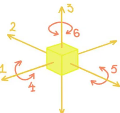
Degrees of Freedom or DoF is how much a rigid body can move in a three-dimensional space. The most DoF a ridged body can have is six, see figure 1, where you have:
1. Movement along the X-axis 2. Movement along the Y-axis 3. Movement along the Z-axis 4. Rotation around the X-axis (Roll) 5. Rotation around the Y-axis (Pitch) 6. Rotation around the Z-axis (Yaw)
(API Marketing, 2019)
2.3 Use of spherical coordinate system
There are a several different uses for spherical coordinate system, the following chap-ter will present and describe two types of robots that use this system: spherical robots and surgical robots.
2.3.1 Spherical robots
Spherical coordinate system is used as a driving system in spherical robots. Typically, the robot includes its drive system (mechanism, control devices and energy sources) inside a ball-shaped outer shell. In order to make the outer shell rotate the drive system needs to transfer power to the outer shell.
Axis of rotation (z-axis)
Rotation angle (alpha)
Displacement of mass
Weight
Figure 2: Illustrates the pendulum drive system for spherical ro-bots. Redrawn from Chase & Pandya (2012).
THEORETICAL FRAMEWORK
7
Generally, it moves through a mechanical fixed component like a gear and an electro-magnetic device like a motor (Chase & Pandya, 2012).
Spherical robots move through a holonomic system which in robotics is a system where the orientation does not affect the desired direction of movement. In comparison to a vehi-cle that must point its front in the same direction as intended direction of movement, a spherical robot can change its direction at any stage of movement (Chase & Pandya, 2012).
There are a several versions of spherical robots due to numerous ways to solve the problem of developing an internal drive system that provides three-dimensionally rotations independently from the outer shell. Considering that the shell needs to be connected to the inner drive system in some way. The most common type of spherical robots moves by shifting the sphere’s centre of gravity. As the sphere’s internal drive system move, the mass distribution will shift, which will cause the sphere to roll to a new position of equilib-rium, which is illustrated in Figure 2 on p. 6. This is because a robotic sphere wants to rest in equilibrium (Chase & Pandya, 2012).
Spherical robots have been used for moisture measurement in crop fields by obtaining and geo-referring environmental data, in child development studies where the young chil-dren interact with the ball as well as in underwater experiments (Chase & Pandya, 2012).
2.3.2 Surgical robotic assistant
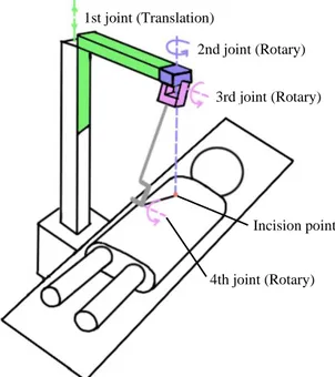
Mirbagheri, Farahmand, Meghdari and Karimian at Sharif University has developed a robotic cameraman to assist the surgeon during a laparoscopic surgery i.e., medical imag-ing. This procedure is usually handled by a human assistant who is responsible for holding the camera and monitoring the laparoscope on the surgeon’s commands. The procedure needs coordination between the surgeon and the assistant, which can be difficult to main-tain through the entire procedure. The developed robotic cameraman, see figure 3, requires four degrees of freedom i.e., three rotational and one translation (Up/down). This basically means a spherical movement is needed for the robot (Mirbagheri, et al., 2011).
1st joint (Translation)
2nd joint (Rotary)
3rd joint (Rotary)
4th joint (Rotary) Incision point
Figure 3: Example of robotic assistant including four degrees of freedom. Redrawn from Mirbagheri et al. (2011).
Figure 5: Example of a robotic assistant including five de-grees of freedom. Redrawn from Muñoz et al. (2006).Figure 6: Example of robotic assistant including four degrees of
8
There are two categories of mechanisms that has been combined to construct this robot. The first includes mechanisms that allows remoting the centre of motion which means that, for example, if the camera is placed on this point, it can be forced to pivot around the point and achieve spherical movements (called active joints). The second category includes mechanisms that in the most distal wrist joints has limited rotary degrees of freedom (called passive joints).
This means that if the camera is held by the wrist, spherical degrees of freedom can be provided but the orientation of the camera must be controlled by position the tip of the camera. Generally, the first category offers more precise result as well as more stable plat-form for the surgery. However, the second category includes low-cost mechanisms since they are simpler and automatically adjusting the patient.
This robot is designed to be effective and low-cost. Therefore, both categories have been combined. The robot has one linear and two rotary joints as well as one limited en-coded rotary joint, see figure 3 on p. 7 for position of the joints.
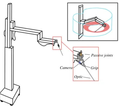
Muñoz, Garzía-Morales, Perez del Pulgar et al. at University of Malaga has designed a similar robot but this has a mechanism of five degrees of freedom composed of two com-ponents, see figure 4. This robot uses Cartesian movement controls to gently generate a spherical trajectory to position the camera. A typical prismatic joint configuration or slider configuration consists of three DoF. This configuration is supposed to position the camera as well as a passive wrist joint with two DoF. This is supposed to achieve required orienta-tion (Muñoz, et al., 2006).
Passive joints
Grip Optic
Camera
Figure 4: Example of a robotic assistant including five degrees of freedom. Redrawn from Muñoz et al. (2006).
9
2.4 Development of flexible products
Flexibility in products can be defined as “the ability to adapt to changes easily and re-versibly” (Bischof, 2010, p. 18), where easily refers to economic and rapid change while reversibly refers to the ability to change back to original form. According to Ulrich & Ep-pinger (2014) a product is defined as something that an enterprise is selling to its custom-ers in order to satisfy their needs. To include flexibility in products, the products can both rapidly be adapted to changes but also be adapted to specific customer needs, which will expand the customer group. When the product can be adapted to satisfy a larger customer group the product is more generalizable due to it not being designed to accomplish certain characteristics.
2.4.1 Rack-and-pinion mechanism
The rack-and-pinion mechanism is one example of making a product flexible. For ex-ample, racks and pinions are used for drilling machines as well as positioning devices. For the drilling machine racks and pinions are used to adjust the height of the table, see figure
5. Regarding positioning devices, some examples of devices that can need positioning for
making up-and-down height adjustments are cameras and sensors.
Racks and pinions are usually used to convert circular motion to linear and vice versa. The mechanism involves a rectangular bar (the rack) having teeth on one side that cooper-ate with teeth on the smaller gear (the pinion), see figure 6 (Britannica, 2021).
The most common application for this mechanism is for steering cars. By using a gear system can the steering wheel’s circular motion be translated into linear motion to turn the direction of the wheels. Another feature of the mechanism is that it also provides gear re-duction to make it easier to turn the wheels. The gear rere-duction will be accomplished by connecting the pinion gear to the steering shaft, which will make the gear spin and move the rack while the steering wheel turns, see figure 7 (Heart Autos, Inc., 2021).
Pinion
Rack
Figure 6: Illustrates a rack-and-pinion mechanism. Redrawn from Britannica (2021).
Rack and pinion
Figure 5: The rack-and-pin-ion mechanism within drill-ing machine use. Redrawn from CarThrottle (2019).
Figure 7: The rack-and-pinion mechanism within car steering use. Redrawn from Ryan (2002-2017).
10
2.4.2 Spring-loaded-device mechanism (Plungers)
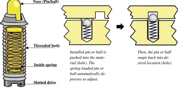
Plungers are mechanical components usually used to position and lock objects. There are two types of plungers: spring plungers and ball plungers. To lock and locate separate components spring plungers are used. Unlike spring plungers, ball plungers have a ball as nose, instead of a pin, and allows movement in and out of position. The disadvantage with ball plungers is that they are not designed to allow movement when applying a side-force as well as heavy side-load (Monroe, 2020). The different elements a spring/ball plunger con-sists of is illustrated in figure 8.
The mechanism of a plunger works through a contact force that puts pressure on the nose of the plunger (ball or pin), then the nose depresses into the body of the plunger and force the internal spring to compress. The compressing spring allow the contact force to position the nose into the desired area, see figure 8. This type of plungers is used to lock something into a certain position. But it can also be used as a cushion between two objects when the plunger depresses only to a certain point which allows little space between the objects. In addition, another application is as support between objects. When the plunger nose depresses as it comes in contact with an object, it pushes out until the object is lined up with an object next to it i.e., adding support from side force. This mechanism can rela-tively easy be applied in devices and equipment (Monroe, 2020).
Installed pin or ball is pushed into the mate-rial (hole). The spring-loaded pin or ball automatically de-presses to adjust.
Then, the pin or ball snaps back into de-sired location (hole).
Slotted drive Inside spring Threaded body Nose (Pin/ball)
Figure 8: Illustrates the mechanism of a plunger and its elements. Redrawn from Monroe (2020) and Pivot Point Inc. (2021).
11
2.5 Agile methodology
Working in an agile way includes shorter steps of work, called sprints, where every step lasts less than a month. This involves the customer in a more structural and recurrent manner because the result is presented after each sprint where the customer is “forced” to have opinions. Therefore, the customer is frequently involved which gives the customer the opportunity to change, add or remove requirements or goals from the thesis. In summary, agile method is more like a philosophy than a structural method that has the purpose to re-peatably and more effective than traditional methods manage changes. Changes that can occur due to new insights as well as changed market conditions (Gustavsson, 2020). In ad-dition, the agile methodology has made it easier to develop prototypes and get rapid user feedback (Birkinshaw, 2018).
2.5.1 Design thinking process
Generally, the Design Thinking Process can be described as an analytic and creative process that generates opportunities to create and prototype models, experiment, collect in-formation as well as redesign. However, it is also described as an agile, iterative, explora-tory and partly a chaotic process where it starts from abstract specifications and gradually the specifications are refined to create the product the company and customers are satisfied with. In several areas, Design Thinking is based on knowledge generated through action in which the results have been evaluated (Razzouk & Shute, 2012).
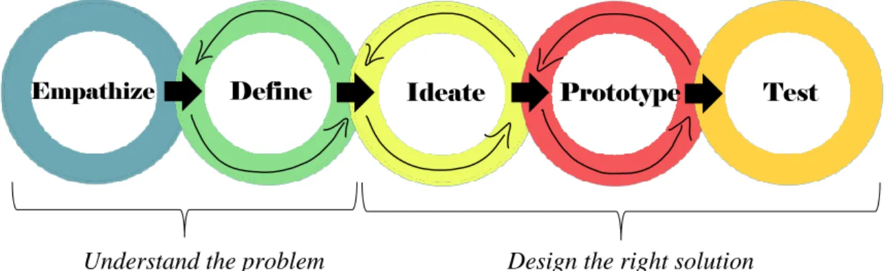
The process includes five steps (empathize, define, ideate, prototype and test) that usu-ally follows in an iterative order which tend to be more effective than following them in designated order, see figure 9. The first two steps, empathize and define, brings an under-standing of what the customer want, bringing clarity to the design as well as defining the problem by discovering connections and patterns related to collected information. Ideation combine your understanding of the problem and customers with your creativity to generate possible solution concepts. Thereafter, you need to communicate your ideas to your even-tual team member(s) or customers as well as test the possibilities. This can be made through prototypes which can be sketches on paper or computer based but it can also be physical models (Shanks, 2010).
Empathize Define Ideate Prototype Test
Understand the problem Design the right solution
12
Typically, there are two types of people working with this process: finders or makers. Finders are more focused to discover, understand and explain the phenomena that being studied while makers are focused on producing what they know in new concepts, construc-tions, arrangements and patterns. In addition, typical techniques for this process depends on the person or group, if they are novices or experienced engineers. Novices tend to use trial-and-error techniques to generate design solutions, test and evaluate it as well as gener-ate another design solution. Experienced engineers tend to use employed integrgener-ated design strategies and make preliminary evaluations of the design solution before prototyping and testing (Razzouk & Shute, 2012).
2.6 Additive manufacturing (3D-printing)
Through 3D-printing three dimensional solid objects can be produced from a digital file. 3D-printing is an additive manufacturing method that produce objects by laying mate-rial in successive layers until the object is produced. This method is often used for proto-typing as it can produce parts quite quick as well as create complex shapes using less mate-rial compared to other manufacturing methods.
Regarding the quality of the 3D-printed objects it primarily depends on the height of each layer, the smaller each layer is the better print quality. However, a small layer height also means that it will take longer to complete. Therefore, this method needs balance be-tween quality and print speed (Chakravorty, 2020). In addition, the 3D-printed model can sometimes differ from the computer-based model due to the precision of the printer. There-fore, it is important to respect tolerances (number of allowed quantities). This difference can occur due to, previously mentioned, layer height. However, it also can depend on size of the printer, spacing between objects as well as shrinking which will result in a smaller model (Sculpteo, u.d.).
Further, the quality can depend on the direction of the layers. If the printed model will be exposed to a load the direction of the layers can be crucial for the strength. Hence, a 3D-printed model is the weakest when loading occur along the direction of the layers.
13
3 Methodology
Following section will present the methodology of the thesis, how it will be
ap-proached. Terms such as action research, literature study, empirical study, data collection and analysis as well as source criticism (validity and reliability) will be presented and ex-plained.
3.1 Research methodology
The research design that this thesis will follow is called action research and is defined as an approach where the researcher and the client or customer collaborate to develop a so-lution to the problem. In other terms action research is characterized by collaboration be-tween the researcher and an organisation member in order to find solutions to organisa-tional problems (BRM, 2021).
This approach can be divided into three categories: positivist approach, interpretive ap-proach and a critical apap-proach. Positivist apap-proach is the most common and is about testing hypothesis in a real-world environment. Interpretive approach is more theoretical, instead of practical tests it focuses on specifying solutions through studies of local and organisa-tional factors. Finally, critical approach is about being critical to processes and aims for improvements (BRM, 2021).
Advantages of action research are high level of practical research, tolerant with both qualitative and quantitative data as well as possibility to get in-depth data about a certain problem. Disadvantages are difficulties to separate action and research and ensure that both has been accomplished as well as lack of repeatability due to the practical elements of the approach (BRM, 2021).
In summary, action research is based on evaluation and critical analysis of practical tests in order to define improvements to specific situations and their context (BRM, 2021). Action research seem to have a link to the Design Thinking process, see p. 11, due to pri-marily the action-based method. However, it is important to distinguish between Design Thinking and action research as Design Thinking is not a method but a mindset. Thus, this thesis will combine action research as well as an agile methodology and Design Thinking.
3.2 Literature study
This thesis has included a literature study in purpose of gaining a theoretical back-ground to the research question. The literature study resulted in three main parts:
a) A description of different techniques of imaging breast tissue that are used today. b) A description of different applications that uses a spherical coordinate system. c) A description of the agile development process, mechanisms used to develop flexible products as well as 3D-printing as prototype tool.
14
The study was based on document studies. There are different types of documents; offi-cial documents such as scientific publications and statistics from public agencies, docu-ments and statistics from companies, media docudocu-ments or news as well as archival materi-als (Säfsten & Gustavsson, 2020). This study was based on secondary data in form of peer-reviewed scientific articles, books as well as documents from agencies or companies re-lated to the area.
3.3 Empirical study
Besides the literature study this thesis has conducted an empirical study where the pur-pose was to investigate how the transmitter stand could be designed to achieve the custom-ers’ requirements i.e., collecting data needed to answer the research question. The empiri-cal study was based on an action research methodology where primary data were collected, data in form of market research, concept development and prototype tests.
Concepts and prototypes were developed during four sprints about three weeks each and were accomplished through a Computer Aided Design (CAD) program as well as 3D-printers. This study was based on the CAD program called SolidWorks which is used to visualize design and functions of a product. Usually, CAD is used to reduce the need of making physical models because prototype producing often is both costly and time con-suming. However, it also facilitates the prototype producing due to it being combined with a 3D-printer to print the modelled objects into physical models.
The empirical study resulted in two main parts:
a) A description of identified customer requirements
b) A description of how the concepts have been generated and modified through func-tion prototypes.
3.4 Data collection and analysis
To collect scientific publications, within the area, for the literature study the databases ABI/Inform and Google Scholar were used via the library of Mälardalen University. To collect authority and company publications Google were used. Search terms such as
Mam-mography, tomosynthesis, biopsy, ultrasound, breast imaging, techniques, robots, spheri-cal coordinate system, spherispheri-cal robots, spring-loaded-device, plungers, rack-and-pinion mechanism, agile methodology, design thinking, 3D-printing and degrees of freedom were
used in different combinations to find relevant articles for the study. To ensure that the arti-cles found via Google Scholar were reliable and peer reviewed Ulrichsweb was used. Ex-cept collections of document data, this thesis has also collected empirical data through CAD and observation of testing of 3D-printed prototypes as well as meetings with the cus-tomers. The 3D-printer type that have been used to produce function prototypes is called Ultimaker 2+ with Polylactide (PLA) as print material.
The collected material has then been analysed through an analysis method called con-tent analysis. This method is a scientific tool that offers new insights, increases understand-ing of a certain phenomenon and informs practical actions (Krippendorff, 2019).
15
Qualitative content analysis is the most common analysing method for written material. This is because of its systematic quality due to all relevant material is taken into account in several steps. This means that content analysis requires a lot of trustworthy data because the method collects a wide range of qualities (Elo, et al., 2014). This method can be ap-plied in a wide range of data used within different fields to find correlations and patterns among different concepts. It is also used to understand intentions of an individual, group or organization, identify bias, revealing differences in different contexts as well as analysis consequences of content such as flow of information or interview responses.
Content analysis can be divided into three main steps excluding collecting data; decon-struction of data in smaller parts and categorising, coding data which means defining rules for which data are relevant and will be included as well as analysing the results and draw conclusions (Luo, 2021).
3.5 Process of concept development
For the empirical study, this thesis has used Design Thinking and followed the generic process of concept development that Ulrich and Eppinger presents in the book product
de-sign and development (2014). The process includes several activities that can be followed
in a certain order or iterative order. This thesis will work iteratively with identifying the customer needs, product goal specifications, concept generation, concept choice, concept testing and prototype development.
3.5.1 Identifying of customer requirements and specifications
The purpose of identifying customer needs is to create a high qualitative information stream between the target group and the product developers. In addition, identifying the re-quirements of the customers leads to a greater chance of achieving high customer satisfac-tion. The difference between requirements and specifications is that requirements describe generally what the customer wants and specifications describes in detail how the product will achieve the needs (Ulrich & Eppinger, 2014).
3.5.2 Concept generation
The purpose of this step is to research several product concepts that are possible solu-tions to satisfy the customers. The generation includes extern research, creative problem solving within the project group as well as systematic investigation of sub-solutions that the group generates (Ulrich & Eppinger, 2014).
3.5.3 Concept choice
The next step is to analyse and successively eliminate product concepts to identify the most outstanding solution. This method is often treated by several iterations i.e., can lead to further concept generation and further development (Ulrich & Eppinger, 2014).
16
3.5.4 Prototype development and concept testing
Every stage in the process of concept development involves different forms of models or prototypes such as physical prototypes or analytical models which helps the developers to demonstrate how well a concept can be accomplished or to evaluate design and ergo-nomic or to demonstrate ideas to customers (Ulrich & Eppinger, 2014).
Concept testing has the purpose of identifying any defects that needs to be solved dur-ing further development as well as verifydur-ing if selected concept is achievdur-ing the customer needs or if changes are necessary. One way to test concepts are through any forms of pro-totypes (Ulrich & Eppinger, 2014).
3.6 Validity & reliability
When using document studies as data collection method source criticism is important because publication via internet is available for almost everyone. Common criteria that are used for evaluating the source are whether the data are true, within a fair range of time, in-dependent, objective as well as competent (Säfsten & Gustavsson, 2020).
According to Kristina Säfsten and Maria Gustavsson validity is “the extent to which what is measured/observed corresponds to what was intended to be studied (internal valid-ity) and in which contexts the results are valid (external validvalid-ity)” (Säfsten & Gustavsson, 2020, p. 224). In other terms validity ensure that a method measures what is intended to measure i.e., the produced results are comparable to real properties and changes in both so-cial and physical world. Reliability is “the ability to repeat an observation and get the same results” (Säfsten & Gustavsson, 2020, p. 224).
To ensure the validity of this thesis data triangulation will be used. Triangulation have been made when more than one researcher, method or data source have been used for the study, (Säfsten & Gustavsson, 2020). Triangulation have been used for this thesis by use of different types of data sources: secondary data such as scientific articles, books and com-pany documents but also primary data from tests of physical prototypes. However, this the-sis has also been approached by two researchers. To ensure reliability, ability to repeat, methods of primarily the empirical study will be presented and described as detailed as possible including figures.
17
4 Action research
Following section will describe how the empirical study has been conducted and what has been done as well as describing the current construction of positioning the transmitter, in other terms this chapter is the basis of the result section.
4.1 Current design of positioning the transmitter
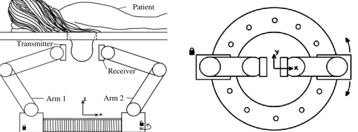
The idea of the MDH robot includes one circular plate as base where the two three ar-ticulated arms are attached to, see figure 10. The receiver arm is thought to move along this plate while the transmitter arm is thought to be fixed. At the end of the fixed arm are a cy-lindrical transmitter attached whilst at the end of the other arm is a receiver. These are then attached to a module that will move through use of a spherical coordinate system. This, in order to position them along the curvature of the breast. In this case the microwave system is an active system with a radar approach. The procedure of scanning and examining the breasts will be performed by the patient laying down on an examination table where the breasts are hanging down through a hole in the table. The breast will then be examining by placing it between the two arms, see figure 10.
4.2 Developed design of positioning the transmitter
During the development process, the process of concept development has been used in an iterative order. However, several requirements, that was needed to take into account during the development, from the primarily customers have been identified. Thereafter, concepts have been generated, produced as prototypes, tested, evaluated and modified. To investigate the possible positioning solutions of the transmitter the authors, in consultation with the research team, decided to design a stand to visualize the final positioning solution of the transmitter. As the first tests will be performed on a ceramic model with a diameter of 100 mm the development process has been based on this model. The ceramic material has approximate properties as a breast which gives the possibility to use it as a simulated breast. This resulting in a stand fully adapted to this model. However, the stand will also be possible to adapt to other sizes and forms.
Receiver Transmitter
Arm 1 Arm 2
Patient
18
4.2.1 Identification of customer requirements
The customer requirements were identified through a meeting with the research team. As mentioned in the previous chapter the idea of the stand to the transmitter was to have a similar arm as to the receiver, namely an articulated arm, which still is planned. However, to be able to make the first tests, the design of the transmitter stand needed a less complex design including position under the breast model instead of beside it, see figure 11.
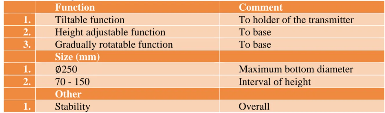
Further, three requirements refer to the function of the stand. Firstly, the customer wanted the holder of the transmitter being able to “tilt” i.e., follow the curvature of the breast. As it makes it possible to adjust the transmitter’s position in relation to the form of the breast as all breasts are not similar to each other. Secondly, the stand requires an adjust-able function to the be adjust-able to change the height as the length of a hanging breast can vary from individual to individual. Thirdly, the stand will be able to rotate gradually as it will cover as much as possible of the breast model which will generate as true measurements as possible. In addition, there is a predetermined requirement referring to size as there is a limited space where the stand will be positioned. Lastly, an important requirement refers to overall stability of the stand as instability would occur a worse condition for good meas-urement results. In table 1, a collection of all requirements will follow.
Table 1: Customer requirements.
Function Comment
1. Tiltable function To holder of the transmitter
2. Height adjustable function To base
3. Gradually rotatable function To base
Size (mm)
1. ∅250 Maximum bottom diameter
2. 70 - 150 Interval of height
Other
1. Stability Overall
Figure 11: Position requirement of the trans-mitter stand is illustrated.
.
19
4.2.2 Sprint 1 - Development of first concept
To define the first concept the authors discussed possible solutions to the stand that in-cluded the requirements. Thereafter, the ideas were modelled in SolidWorks and followed by a several function prototypes produced with a 3D-printer. The purpose of the prototypes was to test the functions to control that them actually work as well as control the size.
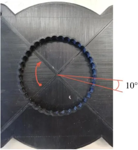
To include the three function requirements the solution was divided into three parts: a bottom part, a middle part and a top part. Figure 12 is presenting the assembled function prototype. The bottom part will make the stand rotate gradually. The idea of accomplishing this function was to have one part that includes a ball, or similar, attached to a spring, i.e., spring-loaded-device mechanism, see figure 13. This part will then be assembled on a fix part including a track in which the ball will follow to achieve the gradually rotating move-ment, 10 degrees in each step, as well as making a clicking sound, see figure 14.
Top Part
Middle Part
Bottom Part
Figure 12: Presents the first concept of assembled transmitter stand.
Figure 13: Presents spring part of the bottom part.
10°
Figure 14: Presents track part of the bottom part.
20
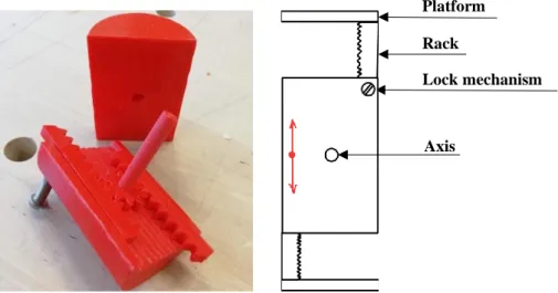
The middle part will achieve the requirement of being able to adjust the height. The idea of the adjustable function includes a rack-and-pinion mechanism, see figure 15. This mechanism will be placed into a cylindrical shell. When an axle drives a gear, the gear will drive two racks in which the racks will raise a platform, for the transmitter holder. To lock the stand at a certain height the idea was to use a screw to make the racks fixed at a certain position.
Regarding the top part it has the purpose of achieving the tilt function. To accomplish this, the idea was to use a gear that drives a curved gear rack. Then, the transmitter will be placed on the gear rack that is held in by a pin construction. In this way, the gear rack will be able to make a U-shaped movement, see figure 16.
Lock mechanism Platform Rack Axis Transmitter Gear Breast model Gear rack Pins
Figure 15: Presents the first concept of the middle part.
Figure 16: Presents the first concept of the top part.
21
4.2.3 Sprint 2 - Development of second concept
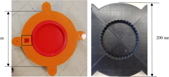
The second concept is primarily a development of the first concept, the functions that were not working or were not working good enough as well as the parts that were too over-sized or underover-sized had to be developed and adjusted. Figure 17 shows the second concept as an assembled stand.
During testing of the bottom part, the authors realized that it was oversized as well as there were no margins between the components that would be assembled. With that aside, the function of it worked as intended. The bottom part of the second concept was therefore based on changes about downsizing, see figure 18, and adding margins between parts that would be assembled. In addition, a gap has been added to mark the number of degrees the stand has been rotated, see figure 18.
150 mm 200 mm
Top Part
Middle Part
Bottom Part
Figure 17: Presents the second concept of assembled transmitter stand. .
22
The function of the middle part was also shown to work as intended. However, oppo-site to the bottom part this part was too small and therefore too unstable, in other terms it was difficult to make it stand by itself. Further, due to support material was missing in the first concept it causes instability, for the gear racks, when they were positioned at the high-est mode. The second concept is therefore based on changes about upsizing and adding material, see figure 19.
The top part, in comparison with the other components needed further development ex-cept upsizing and adding margins between the assembled components. The first conex-cept included small pins that hold the curved gear rack which was making it unstable. To stabi-lize, the walls was raised in which the gear rack was supported better than with just small pins.
In addition, it was difficult to be sure that the curved gear rack could be set to the same degree several times which will make it difficult to get correct measurement values. To make sure that the user knows how the gear rack has been adjusted a spring-loaded-device mechanism was added. Instead of one gear that drives the gear rack, two gears have been added as well as another gear that drives in connection with a spring-loaded-device to mak-ing a gradually movement and a clickmak-ing sound, see figure 20.
In other terms, the top part of the second concept has a design that combine the func-tions of the bottom and middle part, namely a rack-and-pinion mechanism as well as a spring-loaded-device mechanism.
Figure 19: Presents the second concept of the middle part.
Figure 20: Presents the second concept of the top part.
23
4.2.4 Sprint 3 - Development of third concept
The third concept includes further development of the top part and the middle part from the second concept. Dur-ing tests and after feedback from the research team the au-thors realized that instability occurs in the middle part as well as the top part was not adjustable for different breast curvatures due to the gear rack was following a predeter-mined curve.
Due to instability the middle part was developed in a way that includes wider racks as well as four smaller sup-port pillars, see figure 21. The reason for rectangular pillars was due to the prototype method: 3D-printing. To get strong cylindrical pillars they have to be halved to print them and thereafter be assembled. A homogeneous con-struction element is stronger and therefore the rectangular pillars.
The top part was developed from a gear rack following a track to a free-standing trans-mitter holder which makes it possible for the holder to tilt in a much wider range. The holder also offers space underneath for the wires to the transmitter. This concept includes three movements unlike previous concepts that included one. This has a rotational move-ment for the arms, that holds the transmitter, as well as the transmitter holder. However, the arms also include tracks which gives the potential to adjust the holder up and down, in a linear movement, along the curve of the breast, see figure 22. In addition, the movement for the arms is controlled by a spring-loaded-device mechanism to offer a gradual setting.
To tell the user how the transmitter holder has been adjusted (rotated) a type of com-pass will be used. Thus, the direction of gravity goes downward, an arrow formed metal plate linked to the transmitter holder will form a type of compass based on gravity, to show the degrees, 0-180, rotated at a board, see figure 22.
Figure 21: Presents the third concept of the middle part, in highest mode.
Figure 14: Presents the third concept of the middle part, in highest mode.
Figure 22: Presents the third concept of the top part.
Breast model
Transmitter holder Transmitter
Arm Compass
24
4.2.5 Sprint 4 - Development of fourth concept
The fourth concept includes further development of the top part from the third concept. Feedback from the research team included that they rather would have the arms moving along x-axis than a clicking mechanism which makes the concept able to adjust to different diameters of breasts. In addition, the research team also noted that the function of making the transmitter holder being adjusted up and down is not necessary that the authors thought due to the middle part is adjusting the height. Overall feedback included uncertainties about the stability, it seemed to be a weak and unstable construction.
The further development resulted broadly in a completely new design, see figure 23. The clicking mechanism was removed to make it move along just the x-axis instead of both x- and z-axis. The arms were designed without tracks as well as with the transmitter holder positioned in the ends which will make it rotatable. In addition, the arms are no longer angle adjustable instead they are fixed with the ends pointing upwards. However, the gravity-based compass was still included in this iteration. To clarify, the stability is en-sured by the moving parts that can be locked through use of screws, see figure 23.
Transmitter holder
Arm
Figure 23: Presents the fourth concept of the top part.
25
5 Results
Following section will present the result of the accomplished work (empirical study). In other terms the investigation of the research question, presented in the introduction sec-tion, will be based on the data presented down below.
After an analysis of the current design of positioning the transmitter as well as a thor-ough research process to identify customer requirements has different concepts been gener-ated and modified in purpose of developing a flexible design to the transmitter stand during a timeframe of 15 weeks. The main issue that this report has discussed is that the research team of MDH who are developing a microwave breast imaging robot was searching for an alternative way to position the transmitter. This, in order to be able to start with prelimi-nary tests. The idea of the new alternative way of positioning is illustrated in figure 24.
The development process resulted in a fully operative function prototype, called Trans-mitter Adjustable Platform (T.A.P), including a design consisting of three distinct parts where every part had different functions, see figure 25 on p. 26. As this stand will achieve same adjustable purpose as the current design these movements are required to accomplish good test results due to the fact that the transmitter will be positioned in a three-dimen-sional space.
The top part was designed for two movements, namely a movement along x-axis as well as a movement around y-axis. The former movement make it possible to adjust inde-pendently of the breast size, up to a diameter of 100 mm, while the other movement posi-tion the transmitter along the breast curvature. However, a gravity-based compass will clar-ify how the transmitter has been angle adjusted, see figure 25 on p. 26.
Figure 24: Illustrates the final positioning solution of the transmitter in relation to receiver and patient body.
Transmitter
26
The middle part was designed to adjust the height of the stand in purpose to position the transmitter independently on the breast length. In detail, the height can be adjusted be-tween 70-140 mm, see figure 25, which was made with a rack-and-pinion mechanism. In addition, to retain stability this part also includes some support pillars.
Regarding the bottom part, this is aiming for a rotational function in purpose to position the transmitter around the breast (z-axis). This part includes a spring-loaded-device mecha-nism in order to give a clicking-sound as well as achieve a gradual movement, ten degrees at a time, around the breast. Therefore, it will make it easier to control the movement. In addition, the bottom part includes a marking on how many degrees it has been rotated, see
figure 25.
See appendix A for a specification as it will visualize how these functions will achieve the required positioning.
70 mm 140 mm
Figure 25: Presents the prototype of the final positioning solution including its different elements and functions.
27
6 Analysis
Following section consists of four parts. The first part presents if and how the research question has been answered. Following part is an analysis of the final product design. The two last parts presents an analysis of the working process as well as if and how the pur-pose, aim and requirements have been fulfilled.
6.1 Regarding the research question
RQ: “How can a product be designed to position and adjust a microwave transmitter to various locations in order to help testing of cancer research equipment?”
The main issue with this thesis was to develop and examine a design of positioning a transmitter in different ways. This, in order to help the research team to test their existing robot. First and foremost, the research question at hand is now investigated and answered with the help of CAD models and function prototypes.
During the process of making the final design, many iterations were made, these itera-tions made it clear that the research question has more than one answer. But the final de-sign was not only created to answer the research question, but also had to fulfil the stability and functionality requirements set by the researchers. This is the reason that the first itera-tions needed to be remade. The final design is now good enough for the first testing of the robot.
6.2 Analysis of product design
The final iteration of the product design includes four DoF to control the positioning of the transmitter. Two rotating movements (around z-axis (yaw) and y-axis (roll)) as well as one lateral (along x-axis) and one vertical (along z-axis). This is to have full control over the movement around the whole breast model as well as a suggestion of translating the original spherical movements into this design. As the robotic cameraman, developed by Mirbagheri, Farahmand, Meghdari and Karimian, which is similar to the original construc-tion of stand requires four degrees of freedom (three rotaconstruc-tional and one translaconstruc-tion) the T.A.P is comparable with its four different movements. However, previous design itera-tions also included a diagonal movement instead of the lateral one. This design flaw made the platform unstable and limited the range of breast sizes that could be scanned with the T.A.P.
The final design fulfils the physical requirements where it needed to rotate, change height as well as tilting the transmitter. The tilting part includes a mechanism that Mirbagheri, Farahmand, Meghdari and Karimian calls active joints. Active joints force a point, where the transmitter is positioned, to pivot around this point and achieve spherical movements. This in combination with a translational movement in x-axis the transmitter could be position along the curvature of mostly the whole breast model.
28
The middle part that changes the height of the transmitter still has a few flaws; the racks are jumping out of their guide tracks when turned to much. This needs to be cor-rected before making a high precision prototype. Another of the flaws that was discovered when making the final middle part iteration is that it was hard to operate. This could be fixed with some miner tuning in the CAD files as well as some lighter torquing of the screws holding the middle part together. Overall, the prototyped middle part clearly visual-izes the idea of the T.A.P and how it will position the transmitter up and down.
The rotation part of the T.A.P was deemed fully functional with easy movement and easy to understand controls through the clicking function.
6.3 Analysis of working process
This thesis has been conducted in an agile way regarding the development process of T.A.P while overall arrangement of the thesis has been managed in a more traditional way. The agile process occurred naturally due to the advantage of frequently, during the devel-opment process, making use of new insights from changes and customer feedback. There-fore, the thesis was given an open assignment the agile process has worked very well. With this process the authors could develop concepts based on the customer requirements but also frequently get new insights from the customers. To distinctly follow different phases would just limit the authors in the development process due to the open assignment.
Developing T.A.P in several sprints has been really meaningful for this thesis where the sprints have included concept generation, prototype building and evaluation through a De-sign Thinking process. In addition, the sprints have included communication with the cus-tomers who has analysed and been given their point of views on how the product would develop stability or functionality. This working process has been conclusive so that the the-sis would result in a concept positioning a transmitter comparable to the original construc-tion. Another conclusive factor has been building and testing prototypes of every concept. Through building, testing and evaluating prototypes could explicit data, about what was working and not, be gained and a new solutions could be developed. This is what Razzouk and Shute is called trial-and-error technique.
Due to prototype building and testing as well as communication with the customers could a concept be developed without actively using a method for concept choice such as Pugh Matrix. Therefore, could a fully operative prototype of the T.A.P be produced.
This agile working process has been given new insights and learnings to the authors due to the customer involvement. Developing a product and frequently present partial re-sults to the customers which come with important feedback for further development is something that the authors realized was lacking in previous teaching. In other terms the ability to go back and forth to the customers during the whole development process. Thus, this thesis has showed and clarified the importance of customer feedback, without a satis-fied customer the product surely will stand and collect dust.