MÄLARDALENS HÖGSKOLA UNIVERSITÀ DEGLI STUDI DELL’AQUILA
MASTER THESIS
“Bidirectionality in Model Transformations”
Global Software Engineering European Master
Candidate: Alessio Bucaioni MDH Supervisor: Antonio Cicchetti UDA Supervisor: Alfonso Pierantonio UDA Supervisor: Romina Eramo MDH Examiner: Ivica Crnkovic
Abstract
In Model-Driven Engineering bidirectional model transformations emerged as an important ingredient to cope with scenarios such as change propagation, synchronization and to keep consistent system views whenever changes occurring on some view have to be propagated over the others. However, bidirectional mappings open a number of intricate issues that have been only partially solved by research.
This master thesis identifies a set of features characterizing bidirectional transformations and validates them against two existing approaches. In particular, a benchmark based on the UML2RDBMS transformation and consisting of two different configurations is implemented by means of two different approaches, such as Triple Graph Grammars and the Janus Transfor-mation Language, for understanding bidirectional transforTransfor-mations with respect to the elicited features.
Acknowledgements
This dissertation would not have been possible without the guidance and the help of several individuals who in one way or another contributed to this personal growth.
First and foremost, my utmost gratitude to my advisors Antonio Cicchetti, Alfonso Pieran-tonio and Romina Eramo whose guidance has made this a thoughtful and rewarding journey. Especially, Romina has been a mentor, colleague, and friend and i will never forget how she solely encouraged my work.
It is with immense gratitude that i thank my teacher Henry Muccini whose devotion to the GSEEM program led me live this great experience.
I cannot find words to express gratitude and love to my family, for never discussing my dreams even when these bring me far away from their life. A grateful thank to Giada for having accepted nothing less than me.
I am indebted with my friend and colleague Gian Luca: these six years have not always been easy, but i could not demand a better mate. I wish him the best for his life.
I will never forget my "Swedish family" and all the people who made me live an unforget-table year. I am still astonished how this could have happened, but they entered in my life and they will always be part of it. All my affection to Reyes for having held me when i needed it more.
I would like to thank my friends, especially my long-standing friends, for having taken the blows without never doubting our friendship.
Last but not the least, i thank my grandpas Vincenzo and Terzilio, my aunts Ines and Nun-ziata and the One above all of us, God, for answering my prayers and for giving me the strength to never throw in the towel.
Contents
Introduction 12
1 Background and basic concepts 13
1.1 Model-driven engineering . . . 13
1.2 Models . . . 13
1.3 Metamodels . . . 14
1.4 Model transformations . . . 14
1.5 Bidirectional model transformations . . . 16
2 Bidirectionality and change propagation 17 2.1 Motivating example . . . 17
2.1.1 A non-injective scenario . . . 19
2.1.2 A change propagation scenario . . . 20
2.2 Requirements for bidirectionality . . . 21
2.3 Bidirectionality applications . . . 23 3 Identified features 25 3.1 Reverse . . . 25 3.2 Source/Target relationship . . . 26 3.3 Transformation domain . . . 28 3.4 Tracing . . . 29
4 Existing bidirectional model transformations approaches 30 4.1 Considered approaches . . . 30
4.1.1 TGGs . . . 31
4.1.2 JTL . . . 34
4.2 Related approaches . . . 37
5 Specifiyng and executing the transformation with the selected tools 39 5.1 Non-bijective configuration in EmorF . . . 39
5.3 Change propagation configuration in EMorF . . . 42 5.4 Change propagation configuration in JTL Framework . . . 43
6 Evaluation 44
6.1 EMorF . . . 44 6.2 JTL Framework . . . 45 6.3 Summary of evaluation . . . 46
7 Conclusions 48
A UML2RDBMS transformation in Emorf 50
B UML2RDBMS transformation in JTL Framework 56
Bibliography 59
List of Figures
1.1 The OMG four layers metamodelling architecture . . . 14
1.2 MDE in a nutshell . . . 15
2.1 Simplified UML metamodel . . . 18
2.2 Simplified RDBMS metamodel . . . 18
2.3 UML model . . . 19
2.4 RDBMS model . . . 19
2.5 Modified RDBMS model . . . 21
2.6 Modified UML model . . . 21
2.7 Bidirectionality applications . . . 24
3.1 Diagram of the identified features . . . 26
3.2 Example of an injective function . . . 27
3.3 Example of a non injective function . . . 27
3.4 Example of a surjective function . . . 28
3.5 Example of non surjective function . . . 28
4.1 Feature-based diagram of model transformations . . . 30
4.2 A TGGs in EMorF notation . . . 32
4.3 EMorF. Specification of the metamodels . . . 33
4.4 EMorF. Rules organization . . . 34
4.5 EMorF. Transformation execution . . . 34
4.6 JTL framework architecture . . . 36
5.1 Tranformation execution in Emorf - non-bijective configuration . . . 40
5.2 Tranformation execution in JTL Framework - non-bijective configuration . . . 41
5.3 Tranformation execution in Emorf - change-propagation configuration . . . 42
5.4 Tranformation execution in JTL Framework - change-propagation configura-tion . . . 43
A.1 Package2Schema rule in EMorF . . . 50
A.2 Class2Table rule in EMorF . . . 50
A.3 Attribute2Colum rule in EMorF - Case of an inherited persistent primary attribute 51 A.4 Attribute2Colum rule in EMorF - Case of an inherited persistent not primary
attribute . . . 52 A.5 Attribute2Colum rule in EMorF - Case of an inherited not persistent primary
attribute . . . 53 A.6 Attribute2Colum rule in EMorF - Case of an inherited not persistent not
pri-mary attribute . . . 54 A.7 Attribute2Colum rule in EMorF - Case of a primary attribute . . . 54 A.8 Attribute2Colum rule in EMorF - Case of a not primary attribute . . . 55
List of Tables
Introduction
Model-Driven Engineering (MDE)[19] is a relatively new discipline, which aims to abstract the software development from the implementation technology and to reduce its complexity by shifting the focus from coding to modelling phase. In this model-centric view, models and model transformations become first-class citizens: models may be seen as different rep-resentations of the software while model transformations could be considered as the gluing mechanism between models [21]. Therefore, starting from a model, and by means of model transformations, it is possible to automatically obtain a variety of others artefacts. In particular, model transformations can be exploited for a large variety of tasks, not limited to source code generation, such as analysis, testing, model consistency checking and model synchronization.
The adoption of the MDE paradigm led to a rapid growth of the discipline itself, which is continuously facing more and more complex challenges. Bidirectional model transformation (BX) is a challenge which arises as soon as modifications on the target model are allowed, since those changes have to be mapped back to the source in order to avoid their loss due to target overwriting [23]. A first attempt to develop a standard BX language is represented by QVT Relations (QVT-R), which is included in the Query View Transformation (QVT)[18] by the Object Management Group (OMG). Although affected by several weaknesses, as discussed in[24], it clearly established the relevance of BX in MDE.
The intrinsic difficulty to approach BX resides in the nature of model transformation them-selves, which are in general neither injective [22] nor total [14]: each time a change occurs, more than one reverse function may be available; moreover, in general the transformation only involves a subset of elements of the source and target models. A number of approaches and languages have been proposed due to the intrinsic complexity of bidirectionality. Each one of those languages is characterized by a set of specific properties pertaining to a particular applica-tive domain [5, 23]. Despite the large number of available model transformation approaches and the common understanding about the importance of bidirectionality, there is a lack of stan-dardisation: most of the BX issues are still not properly investigated; more important, there is not a clear understanding on which features a BX language should provide to overcome specific bidirectionality issues.
The contribution of this work is: (i) to identify a set of pragmatic features characteriz-ing bidirectional model transformations and (ii) to validate them against two bidirectional ap-proachesnamely Janus Transformation Language (JTL) and Triple Graph Grammars (TGGs): JTL is a declarative model transformation language specifically tailored to support bidirec-tionality and change propagation [4]; TGGs is a very well-known paradigm that in the last decades was adopted in MDE exploiting the similarities between metamodels, models and graphs schemata and graphs [20]
The UML2RDBMS transformation scenario consisting of two different configurations is implemented by means of the selected approaches for understanding the practicality of bidirec-tional transformations with respect to the elicited features. At the same time an evaluation of the implementations is provided highlighting differences and similarity between the approaches and giving a cue to identify their possible applications. We take into account a different version as the transformation is proposed in the literature, i.e., with the non isomorphic source (UML) and target (RDBMS) modeling languages. In order to apply the approaches to specific con-texts concerning bidirectionality and change propagation, we implement the transformation by means of selected tools.
Outline of the thesis
The thesis is structured as follows:Chapter 1 describes the basic concepts used in this master thesis work. More precisely, Model Driven Engineering (MDE) is introduced together with the definition of models and metamodels. Moreover, the concepts of model transformation and BX are discussed and de-fined.
Chapter 2 presents a motivating example used to discuss the importance of bidirection-ality in MDE and to analyse the major issues and the application scenario. Moreover change propagation, as a bidirectionality application, is introduced and defined.
Chapter 3 identifies the fundamental features of BX used as metrics in the frameworks evaluation.
Chapter 4 gives a formal characterization of TGGs and JTL, based on the feature identifi-cation illustrated before. Moreover, it presents the TGGs and JTL implementations considered for the comparison. Finally it introduces the related BX languages
Chapter 5 presents the implementation of the case study for the selected tools.
Chapter 6 compares the implementations based on the features identified in the Chapter3. Chapter 7 draws conclusions and discusses some perspective works.
Chapter 1
Background and basic concepts
The following chapter provides an overview of some basic concepts used in this master thesis. As first we introduce the concept of MDE along with the concepts of models, metamodels and model transformations. We after move to the world of BX.
1.1
Model-driven engineering
MDE is a young discipline born to fill a historical gap in the software development: contrary to the other engineering disciplines, software development, and computer science in general, did not exploit any form of preliminary design in order to uncover potential issues before the real application was even started to be developed. Such a need has become more and more evident with the ever increasing intricacy of the applicative scenarios taken into account. The usage of models brings some intrinsic benefits primarily addressable to an overall reduction of complexity. Following the principle of “everything is a model” MDE shifted the focus from the coding to the modelling process, promoting models to first-class citizens.
We can describe MDE as a framework which is composed, at least, of: - models,
- metamodels
- and model transformations.
1.2
Models
In the literature we can find several definitions of models. Despite this multitude there is a common understanding on what models are.
Following [3] we can define models as an abstraction of a real system, built with some precise goal in mind. In this context, models have to be able to answer in place of the actual
system; the more models are accurate, the more working with models and models transforma-tions can bring benefits in the software development.
By looking at programming languages and grammars we can say that in the same way a programming language complies to its grammar, a model is said to conform to a precise metamodel if the former is made up of well-formed constructs defined in the latter.
1.3
Metamodels
A metamodel defines the set of all the concepts and rules needed to build an abstraction of the system for a specific purpose. Formally has been argued how the metamodels, and metamod-elling in general, are a way to define the abstract syntax of the models.
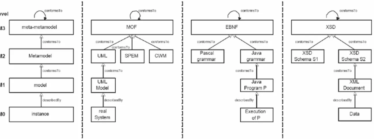
Figure 1.1. The OMG four layers metamodelling architecture
OMG has standardized the concepts of model and metamodel in the well-known four layers architecturedepicted in Figure 1.1. Each layer is defined in terms of the layer above and it is connected to it by means of the conformance relation. The only exception is the last layer, the layer 3, which is reflexively defined in terms of itself.
1.4
Model transformations
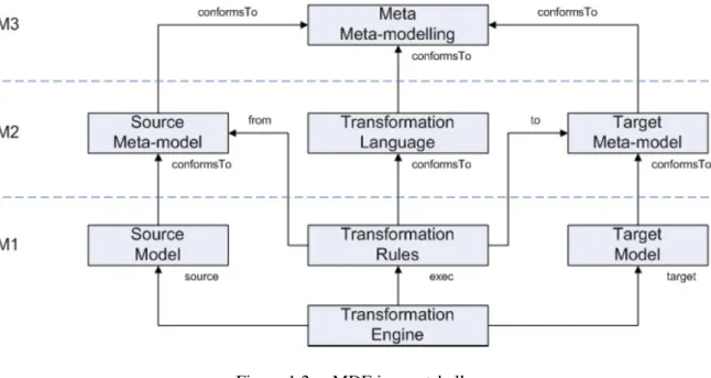
Model transformations can be considered as the core of the MDE framework: without a mature transformation technology the goodness and the efficiency of the framework itself could not be granted. Figure 1.2 places model transformations in the proper context of meta-modelling architecture.
Following the “everything is a model” principle also model transformations could be seen like models: in the same way source and target models conform to their respective metamodels,
Figure 1.2. MDE in a nutshell
in the same way transformation rules conform to their transformation language; all the meta-models, thus the source metamodel the target metamodel and the transformation language, con-form to one meta-metamodel, which belong to the M3 level of the metamodelling architecture depicted in Figure 1.1.
Model transformations can be defined as a conversion process between a source and a target model driven by some mapping relation linking objects in the source model to objects in the target model [15].
Transformation rules basically define a set of mappings between elements of the source and target metamodels; once specified, the transformation is executed from the transformation engine by instantiating the transformation rules on the source and target models.
Although the key role they play, model transformations have been standardized only in 2005 by the OMG Query/View/Transformation request for proposal [18]. Despite the definition of a standard model transformation language the development of new transformation mechanism is still very active. In fact, the belated standardization together with the different needs of both industry and academy ends up in a set of different languages.
In [5] the authors present a feature based diagram for the classification of model trans-formation approaches. In the first level, the approaches are characterized by a set of eight features, which go from the modality of the transformation specification until the aiding mech-anisms such as the tracing. Without loss of detail we can characterize a model transformation approach by establishing how the transformation and the transformation rules are specified and by defining its directionality. More precisely, the directionality of an approach regards the ability of the transformation engine to execute a transformation in more than the forward di-rection, thus from source to target model. Eventually, a transformation engine can also keep
track of the transformation execution information, such as the models elements involved, pro-ducing new namely trace instances. Figure 1.2 depicts a unidirectional scenario in which the transformation are executed in the forward modality.
A transformation is often specified by means of a set of transformation rules; eventually some approaches can contain some extra logic, e.g. pre and post OCL expressions, to constrain the transformation behaviour; usually a transformation specification, being relational, is not executable as it is.
Depending if the approach is graph-based, rather then MOF based or constraint based, the transformation rules are specified in accordance with the related syntax and notation.
In the following, we provide deeper analysis for selected bidirectional model transformation approaches.
1.5
Bidirectional model transformations
The problem of multidirectionality and bidirectionality arose in the MDE community as soon as the MDE framework has been introduced and used in the software development process. In the early phases of MDE the normal work-flow scenario was depicted as a source model to be transformed towards a target model. In this respect, changes were confined to the source model and a model transformation was devoted to restore the consistency between the two models by propagating the changes to the target model. When changes to the target model became a need, the framework had to be enriched by considering bidirectional model transformations in order to keep the consistency between source and target artefacts.
According to [6], a BX is defined as a way to enforce consistency between two models when changes on the target model are allowed. BX face intrinsic difficulties which have been investigated in these last decades. One of the earliest issues is the debate about weather or not a transformation should be written down as a single expression: nowadays there are two main approaches for realizing bidirectional transformations: (i) by programming forward and backward transformations in any convenient unidirectional language or (ii) by using a bidirec-tional transformation language where every program describes both a forward and a backward transformation simultaneously.
Unfortunately these challenges are still open. In the following chapter we introduce and explain the major problems related to the BX by means of a running example.
Chapter 2
Bidirectionality and change propagation
Nowadays the software development cycle is much more an iterative process rather than a straightforward activity: software is often refined and modifications are propagated back to reflect new and more precise knowledge gained within the working domain.
By embracing the MDE vision, models and model transformations are exploited within the whole software lifecycle, ranging from requirements documentation to test phases. Conse-quently, modellers have often to cope with complex scenarios in which models are related via non-trivial model transformations. In the simplest case, model transformations are exploited to establish unidirectional relationships between a source and a target model. However, in the more general case both the source and the target models are modified independently. In this respect, bidirectionality can be seen as a mean to guarantee/ensure the synchronisation/consis-tencybetween models.
Based on this perspective, this chapter discusses the importance of bidirectionality in MDE, posing particular focus on one bidirectionality application, namely change propagation. The structure of the chapter is the following: Section 2.1 introduces the motivating example used through this master thesis; Section 2.2 introduces bidirectionality starting from its requirements while in Section 2.3 relevant bidirectionality applications are showed.
2.1
Motivating example
In this thesis we focus on non-injectivity and non-surjectivity, which are intrinsic and of not-obvious issues related to BX. In order to better illustrate such difficulties, hereafter we will consider the class diagram to relational database (UML2RDBMS) benchmark described in [14, 6], and usually used to validate the salient characteristics of model transformation lan-guages.
The Unified Modeling Language (UML) is a general-purpose modeling language in the field of software engineering. It was developed in 1990 by Grady Booch, Ivar Jacobson and
Figure 2.1. Simplified UML metamodel
Figure 2.2. Simplified RDBMS metamodel
Jim Rumbaugh at Rational Software, but since 1997 is managed by the OMG. In 2000 the International Organization for Standardization(ISO) standardizes UML as industry standard for modeling software-intensive systems.UML is composed by a set of graphic notation tech-niques used to specify, visualize, modify, construct and document the artifacts componing a software system. The UML metamodeling architecture is defined in the Meta-Object Facility (MOF)[17].
A relational database management system (RDBMS) is a database management system for relational databases. A relational database is a way to collect data into a set of formally described tables, which make the data-access easier. A relational database is created in terms of first-order predicate logic database model, namely relational model. The first commercial RDBMS was ORACLE1, realised in 1979 by Relational Software.
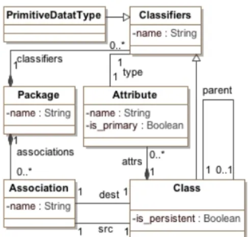
Simplified versions of the UML and RDBMS metamodels are depicted in Figure 2.1 and Figure 2.2, respectively. According to the specification of the UML2RDBMS transformation, each UML package is mapped to a corresponding RDBMS schema, each persistent class to
1
http://www.oracle.com
a corresponding table whose columns are derived from the source class attributes, including the inherited ones. If an attribute is marked as primary then the corresponding column will be transformed as primary key of the related table. Non-persistent classes are not mapped to tables. However, one of the main requirements of the transformation is to preserve all the information of the source diagram. As a consequence, attributes pertaining to non-persistent classes have to be distributed over those tables stemming from persistent classes that access non-persistent ones.
2.1.1
A non-injective scenario
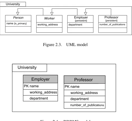
If the transformation involves bijective mappings then the forward transformation is an injective function, and the backward transformation is the corresponding inverse. In this case, by re-applying the transformation from the generated target model, the source model is generated without any ambiguities. However, in the general case the forward transformation can be an arbitrary function and not necessarily bijective. In order to illustrate the difficulties that may occur, in Figure 2.3 an UML model is shown.
Person name {is_primary} Worker working_address department Employer {persistent} University PK name working_address University Employer department PK name working_address Professor department number_of_publications number_of_publications Professor {persistent}
Figure 2.3. UML model
Person name {is_primary} Worker working_address department Employer {persistent} University PK name working_address University Employer department PK name working_address Professor department number_of_publications number_of_publications Professor {persistent} Figure 2.4. RDBMS model
In particular, the packageuniversityis composed of an inheritance hierarchy of classes. The persistent class professor, with attribute number_of_publications, inherits from the persistent class employer, with attribute department. The parent class workeris not
persistent and contains the attributeworking_address. Finally, the top parent non-persistent class person has the attribute name. By applying the UML2RDBMS transformation to the class diagrams depicted in Figure 2.3, the schemas in Figure 2.4 is obtained. In particular, the inheritance hierarchy of non-persistent classes person and worker and persistent class
employeris flattened as a single tableemployerthat has corresponding columns for all the attributes inherited by the other classes in the hierarchy. In general, attributes of the parent classes induce corresponding columns in both the parent and child classes, therefore the ta-ble professor includes all the attributes of the table employer (as mapped to appropriate columns).
The UML2RDBMS transformation gives rise to non-injective mappings, i.e. inherited at-tributes can be restored in more than one way . Furthermore, in order to obtain the original source model from the target, the transformation should be able to preserve all the information of the UML model, i.e. non-persistent classes have to be generated again and attributes have to be restored in the appropriate original classes. Some of these problems can be alleviated by managing tracing information of the transformation executions: in this way, each generated element can be linked with the corresponding source and contribute to the resolution of some of the ambiguities. In particular, those links can be exploited later on to trace back the changes from a RDBMS model to the corresponding UML one. Nonetheless, as showed in the next scenario, traceability links between source and target elements is a necessary but not sufficient condition to support bidirectionality, since, for instance, elements discarded by the mapping may not appear in the traces, as well as new elements added on the target side.
2.1.2
A change propagation scenario
Manual changes might be needed on the generated models in order to resolve unforeseen re-quirements or limited expressiveness of the involved metamodels. By taking into account the running example, any manual modifications of the generated RDBMS model should be back propagated and eventually reflected in the source UML model. Such modifications might in-duce several ambiguities, which need to be managed. For example, let us suppose that the generated model is manually modified as depicted in Figure 2.5.
The first change involves a new columnemail, which has been added in the table
professor. This gives place to an interesting situation since such modifications can be re-flected to the source model in Figure 2.3 in four alternative ways: the attribute (corresponding to the manually added column) can be associated with the classprofessor or with each of the parent classes, i.e.employer,workerandperson, as in Figure 2.6. Consequently, more than one source model propagating the changes exist.
Intuitively, each time a UML model is mapped to the corresponding RDBMS model a
PK name working_address University department PK name working_address Professor [isLocal] department number_of_publications [email] number_of_publications Professor {persistent} Person name {is_primary} Worker working_address department Employer {persistent} University [email] [email] [email] email Employer [isLocal]
Figure 2.5. Modified RDBMS model
PK name working_address University department PK name working_address Professor [isLocal] department number_of_publications [email] number_of_publications Professor {persistent} Person name {is_primary} Worker working_address department Employer {persistent} University [email] [email] [email] email Employer [isLocal]
Figure 2.6. Modified UML model
loss of informationmay cause ambiguities when trying to map back corresponding target revi-sions. As said, some of these problems can be alleviated by managing traceability information. Nonetheless, maintaining trace links between source and target elements is a necessary but not sufficient condition to support.
For instance, if the designer of the RDBMS model in Figure 2.4 wants to specify the lo-cation of the tables (that is whether the data of a given table is retrieved from remote or local resources) the considered model has to be improved and the isLocal attribute of the meta-class Table has to be considered as shown in the new version of the RDBMS model in Figure 2.5. Because of the limited expressive power of the considered UML metamodel, which does not support this annotation, such a revision does not have counterparts in the UML model in Figure 2.6.
2.2
Requirements for bidirectionality
Bidirectionality is a relevant aspect in model transformations: often it is assumed that during development only the source model of a transformation undergoes modifications, however in practice it is necessary for developers to modify both the source and the target models of a
transformation and propagate changes in both directions in order to re-establish a consistency relation [23].
By modelling an unidirectional transformation as a function f : M → N , where M and N are the sets of source and target models, respectively, informally the consistency relation between m ∈ M and n ∈ N is defined such that m and n are consistent if and only if n = f (m)[23].
Stevens [19] formalizes bidirectional model transformation as two functions. If M and N are metamodels and R ⊆ M × N is the consistency relation to be established on the models, a bidirectional model transformationconsists of two functions:
− →
R : M × N = N ←−
R : M × N = M
Given a pair of models (m; n) ∈ M × N , the function−→R changes n to be consistent to m. Similarly,←R changes m in accordance with n.−
Since the definition of bidirectional model transformation does not constrain the behaviour of the transformation, Stevens[19] proposes three properties that a bidirectional transformation should satisfy.
Correctness. This property ensures a bidirectional transformation does something useful. Intuitively given two models m, n, the forward and backward transformations must establish the consistency relation R between them.
Formally given two models m and n, conforming to the metamodels M and N , respectively, a transformation T is correct if:
∀m ∈ M × n ∈ N T (m,−→T (m,n)) ∀m ∈ M × n ∈ N T (←T (m,n),n)−
Hippocraticness. This property prevents a bidirectional transformation from doing some-thing harmful. Given two consistent models m and n, if neither model is modified by users, the forward and backward transformations should modify neither model.
Formally a transformation T is hippocratic if ∀m ∈ M and n ∈ N , we have T (m,n) ⇒−→T (m,n) = n
T (m,n) ⇒←T (m,n) = m−
Undoability. Given two consistent models m and n, suppose that m is updated to m0 and the changes are propagated to the N side. After the transformation the designer realizes that the update is a mistake and he modifies m0 back to m and performs the forward transformation again. The undoability will ensure the latter transformation will produce exactly n to cancel the previously operated modification.
Formally, a transformation T is undoable if ∀m,m ∈ M and ∀m,m ∈ M , we have T (m,n) ⇒−→T (m,−→T (m,n)) = n
T (m,n) ⇒←T (− ←T (m,n),n) = m−
In this master thesis we do not require bidirectional transformations to satisfy the undoabil-ity property since it puts strong requirements on the consistency relation R, practically disabling many currently available transformation approaches.
A bidirectional model transformation is bijective if the consistency relation R is a bijection, thus if R is injective and surjective.
A relation R is injective if does not map different elements of the domain to same element of the codomain. By contrast, a non-injective function could map different elements of the domain to the same elements of the codomain. Such characteristic is typically troublesome since it leads to a non-deterministic situation in which the consistency between the source and target models involved in the transformation can be restored in more than one (valid) way. Taking into account the motivating example presented in Section 2.1 is trivial to notice that the specified transformation is non-injective, since demands both inherited attributes and attributes to be mapped in columns, without a separation of concerns.
A relation R is surjective if each element in the domain has a corresponding element in the codomain. By contrast a non-surjective function could not involve all the domain/codomain elements in the relations, thus rising difficulties in restoring consistency between non-involved elements. For instance, the transformation specified in the motivating example presented in Section 2.1 is clearly non-surjective considering that the non-persistent classes are not trans-formed in tables.
The issues discussed so far can affect BX in a way to invalidate the correctness property. On the one hand, in a non-injective transformation, there could be more than one way to propagate back the changes, thus to restore the consistency. If a BX approach is not able to consider more than one recovery option or to simply select the right one, the transformation will be incorrect.
On the other hand, in case of a non-surjective transformation, the changes could affect a subset of elements not involved in the transformation definition and hence have no available information to propagate those changes back.
From a theoretical point of view it would be sufficient to consider bijective BX; in practice however, most of the actual BX are non-bijective. The intuitive reason resides in the nature of transformation themselves, which in practice involve metamodels with different expressive power.
2.3
Bidirectionality applications
The need of bidirectionality was an early necessity within the MDE community [20]. A fun-damental acknowledgment to bidirectionality came in 2005 by the OMG, which included a
bidirectional language in the QVT standard transformation language, namely QVT Relations (QVT-R). Regardless this formal acknowledgment, the importance of bidirectionality is practi-cally remarked by its large number of application scenarios. Figure 2.7 depicts relevant appli-cations that rely on bidirectionality.
Figure 2.7. Bidirectionality applications
Change-propagation. In dealing with models and model transformations, the modeller may want to perform some manual changes to one of the two models involved in a trans-formation. In this respect, it is important that each change can be mapped back to the other model accordingly. If more than one model propagating the changes exist, is important, for the transformation approach, to be able to generate all the feasible models propagating the change.
Round-trip engineering. Round-trip engineering (RTE) concerns with the change propa-gation of target model manipulations. The source and target models as well as the changes to the target are given, the goal is to produce a new source model such that, once re-transformed, will exactly reproduce the modified target [14].
Synchronisation. Synchronisation actually involves the application scenarios analysed so far. In a synchronisation scenario there are no-constraints on the number of involved models as well as there are no-constraints on the kind of the changes. Two or more models have to be kept synchronisedby propagating changes in any direction even in concurrent or parallel mode.
Multi-view modelling. Separation of concerns is a well-known principle that prescribes the use of multiple points of view to approach a complex problem by means of sub-problems with a typically reduced intricacy. In this respect, very often software systems are specified by means of views, viewpoints and correspondences. Models and model transformations can be exploited to keep the available views synchronised, to propagate changes across them, and for evaluating the impact of the changes.
Chapter 3
Identified features
In the last decade several works proposed different formal characterizations of model mations. We saw how [5] identifies a set of features that could describe any model transfor-mation approach; [14] is another attempt in identifying relevant aspects for bidirectional model transformations approaches.
Although the latter is much narrowed and especially tailored for bidirectional model trans-formations, both characterizations do not provide any meaningful metric to practically evaluate the impact of a certain approach in coping with the intrinsic difficulties of bidirectional model transformations.
In this section, starting from such difficulties we identify a set of pragmatic features, which can characterize bidirectional model transformation approaches and their implementations.
The selected features are utilized as evaluation framework of the considered approaches. Figure 3.1 summarizes the considered features, which are hereafter described one-by-one.
3.1
Reverse
As introduced in Chapter 1 there are two main approaches for realizing bidirectional transfor-mations: (i) by programming forward and backward transformations in any convenient unidi-rectional language, i.e., the backward transformation is given by user (see the entry given in Figure 3.1) or (ii) by using a bidirectional transformation language where every program de-scribes both a forward and a backward transformation simultaneously (see the entry computed in Figure 3.1).
Looking at bidirectional model transformations as a mean to restore consistency between two models, no consistency management on the models is feasible if no consistency between the pair of functions is ensured.
A major advantage of the latter approach is that the consistency of the transformations can be guaranteed by construction. Otherwise, an approach requiring the reverse transformation to be given by the user might be cumbersome and error-prone. In fact, the designer needs
Figure 3.1. Diagram of the identified features
to manually ensure the consistency. More precisely, the user has to guarantee that the given reverse behaves like the mathematical inversion of the forward transformation function, i.e. that f = f ◦ f−1 ◦ f . If this property cannot be guaranteed, synchronization possibilities are reduced [14].
As a consequence, it is not surprising that most of the available approaches compute the re-verse, thus reducing the likelihood of introducing inconsistencies between the pair of functions constituting a bidirectional transformation.
3.2
Source/Target relationship
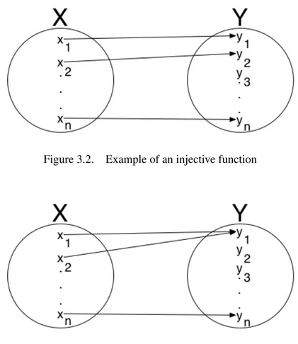
Considering a model transformation as a function, we can formally define what is an injective function: a function R is an injective function if it never maps distinct elements of the domain to the same element in the codomain. Figure 3.2 depicts an example of an injective function, while Figure 3.3 shows a function which is clearly non-injective.
The difficulty faced with bidirectional transformation is the often neglected fact that trans-formations in general are non-injective. In other words, there are different concepts in the source metamodel that are mapped to the same element in the target metamodel. Intuitively this phenomenon is ascribable to the different expressiveness of the metamodels involved in a transformation as well as to the specification of the transformations, which are generally am-biguous. Considering that neither the simplest functions are generally injective, bidirectionality in model transformations raises not obvious issues.
Figure 3.2. Example of an injective function
Figure 3.3. Example of a non injective function
Going in more details, a bidirectional model transformation is injective if the consistency relation is injective, which means that for any model there exists a unique corresponding model which is consistent with it. It is a strong condition since it requires two models to be isomorphic (i.e., the same information represented in different ways).
The ability to specify non-injective transformations is a not obvious characteristic required in the current bidirectional transformation languages.
On the one hand, as soon as modifications to the target model are allowed and they are not propagated back to the source, any further modification on the source model would demand the re-execution of the transformation and the consequent overwriting of the target model, leading to the loss of the changes previously performed on the target model.
On the other hand, if the transformation is non-injective, when applying a transformation to a pair of inconsistent models, there can be more than one way in which consistency could be restored. As a consequence, the correctness [24] of a transformation may not hold whenever more than one way to propagate changes exists.
On the one hand, additional constraints can be added during the implementation of the trans-formation in order to avoid ambiguities. It means that the mappings are made injective, in the sense that there can be only one way, encoded in the transformation, to restore the consistency relation (see the entry selected solution in Figure 3.1).
On the other hand, the transformation is able to generate all the feasible solutions according with the consistency relation (see the entry multiple solutions in Figure 3.1).
3.3
Transformation domain
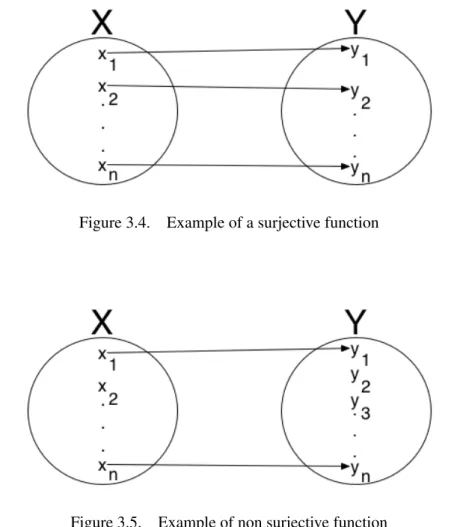
Considering a transformation as a function, the partiality corresponds to a not surjective func-tion (i.e., the image does not cover the whole codomain). Formally we can define a surjective function as follows: a function R is a surjective function if every element x of the domain X is related with at least one elementy of the codomain Y (Figure 3.4).
Figure 3.4. Example of a surjective function
Figure 3.5. Example of non surjective function
Model transformations in general are partial, i.e. there are concepts in the source model that do not have a correspondence in the target model and vice versa (Figure 3.5). The issue in
dealing with partial bidirectional transformation resides in the backward execution: by running the backward transformation, target elements not having a source counterpart may be lost.
A bidirectional approach could deal with a partial domain in two different ways: by modi-fying the transformation with mappings involving the neglected elements (see forced mapping in Figure 3.1) or by implementing a dedicated support to maintain all the information from both the domains (see dedicated support in Figure 3.1).
3.4
Tracing
One of the major difficulties that the MDE community is trying to solve is the lack of standard-ization of the used terminology.
Although there seems to be a common understanding on what tracing means, there is not a standard definition.
Consequently is not even clear what a tracing mechanism should provide.
Czarnecki and Helsen [5] suggest that tracing can be thought as a footprint of a transforma-tion executransforma-tion, thus as a way to catch and record some informatransforma-tion about the actual executransforma-tion. The characterizing features highlighted in that work focus on the modality of traces creation, e.g. automatic or manual, and on the storage location, e.g. in the models file or in a separated file.
Albeit these features can be sufficient to characterize any model transformation approach in a broad sense, they do not state any information about the purpose of such a tracing mechanism. On the one hand, in unidirectional model transformation tracing can be a complement mechanism to perform some further analyses, i.e. impact analyses.
On the other hand, in bidirectional model transformation tracing is a key aspect to solve the intrinsic issues of bidirectionality.
In this respect, it may also be interesting to understand what information the tracing mech-anism is able to record and hence provide a characterization based on the different capabilities. In particular, trace links (see trace links in Figure 3.1) between the transformed source and target model elements may be created and maintained to contribute to the resolution of some ambiguities (for example, when restoring back the attributes in the original classes in Figure2.3).
Furthermore, also the information lost in the current execution of the transformation may be stored: trace elements (see trace elements in Figure 3.1) should be generated each time a model element is discarded by the mapping and then needs to be stored in order to be regenerated during the backward transformation (for example, the added propertyisLocalin Figure 2.5).
Chapter 4
Existing bidirectional model
transformations approaches
This chapter introduces relevant BX approaches, briefly discussing their basic concepts and ideas. The chapter poses particular focus on the two approaches chosen for the comparison developed in this thesis work, e.g. TGGs and JTL, giving a formal characterization of the languages and presenting the related implementations, e.g. EMorF and JTL Framework.
The chapter is structured as follows: Section 4.1 presents the TGGs and JTL approaches and their reference tool EMorF and JTL Framework while Section 4.2 discusses the related bidirectional transformations approaches.
4.1
Considered approaches
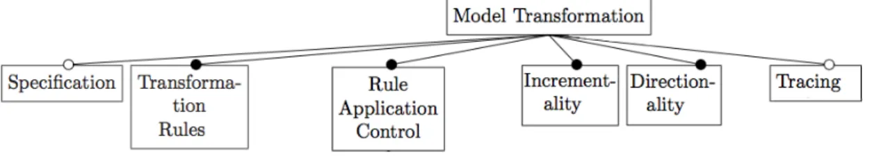
Czarnecki and Helsen in [5] define a framework for the classification of model transformation approaches. The framework is given as a feature-based diagram, thus a hierarchy of features describing the set of instances of a concept. Several levels compose the diagram: the nodes on the top-level represent the features and each sub-node represents a point of variation. For the sake of this thesis work, we consider a subset of the first-top layer.
Figure 4.1. Feature-based diagram of model transformations
Figure 4.1 shows a representation of the considered feature-based diagram; the description 30
of the first-top level features follows [5]:
- Specification, refers to the modality in which the transformation is specified. For in-stance, some approaches can have some OCL pre- and post-conditions.
- Transformation rules, refers to the rules specification.
- Rule application control, refers to the mechanisms which determine rule application, such as the order in which they are executed, i.e. scheduling.
- Incrementality, refers to the ability to incrementally update the target model based on the source model changes.
- Directionality, refers to the possibility of executing the transformation in only one direc-tion or multiple direcdirec-tions.
- Tracing, refers to the mechanism that allows the approach to record aspects of the trans-formation execution, such as the trace links between the transformed elements.
Hereafter, the features illustrated so far will be used to characterize the TGGs and JTL approaches.
4.1.1
TGGs
TGGs as introduced by Schürr [20, 16] belong to the class of graph transformations, and they are considered as a natural framework for specifying bidirectional model transforma-tions. Formally, a triple graph grammar T GG := (T G,R) consists of a type graph triple T G and a finite set R of rules, where T G is a triple of connected typed graphs denoted as G = GS ← GC → GT, while a rule r = (pS,pT,pC) consists of three productions responsible
of transforming the corresponding graph.
Exploiting the similarities between graph schemata and metamodels, graphs and models, in TGGs the three graph schemata represent the source and the target metamodels, and the correspondence metamodel, which keeps track of the links between the source and the target elements. Whereas, a TGGs rule specifies consistency mappings between elements of source and target metamodels. Starting from a TGGs rule specification, which is declarative and use-less as it is, the aforesaid three productions are derived and used in the transformation process by executing them in the forward, the backward and the correspondence mode, respectively. By going into more details, each production is composed of a left-hand side (LHS) and a right-hand side (RHS): whenever elements in the source model bind the LHS of a production, these will be substituted in the source model with the RHS of the production.
The specification of a transformation within TGGs is mainly given by a set of TGGs rules. Most of the current TGGs implementations provide a dedicated editor, which provides support
Figure 4.2. A TGGs in EMorF notation
for the visual syntax and OCL expressions, e.g. assignments and constraints. Figure 4.2 depicts a TGGs rule specification in the EMorF tool notation; it represents one of the rules specifying the mapping between Attribute and Column described in Section 2. Without loss of generality, hereafter rule specifications are given by means of the EMorF syntax to increase the readability and the comprehension.
Intuitively, a TGGs rule specifies consistent mappings between elements of source and tar-get metamodels, e.g., in Figure 4.2 the metaclassAttributeof the source domain is mapped to the metaclassColumnof the target domain. The separation of the metamodels is graphically rendered by vertically splitting the rule in three areas. The top-part of the rule represents a pre-condition, whose elements are marked with the modifier <<bind>>. All the other elements marked with the modifier <<create>> compose the body of the rule. In the bottom part four OCL expressions are visible: they are used to constrain the rule behaviour, i.e. constraint, or to specify the value of certain model element properties, i.e. assignment.
TGGs rules within a transformation are scheduled as based on the preconditions and OCL constrains: whenever the precondition is satisfied, the rule is checked further against its con-straints. If they are satisfied the rule is executed.
TGGs have been often regarded as an incremental technique for model transformation:[10] establishes how TGGs can be exploited for realizing an incremental model synchronisation.
Nowadays there exists a common understanding about the bidirectional nature of the TGGs, which, even if often considered for unidirectional model transformations, are broadly consid-ered as the main approach to cope with bidirectional model transformations.
The considered approach has a natural mechanism for the tracing which relies on the TGGs paradigm itself: in fact, the correspondence model is generated in each transformation execu-tion and is able to record all the mappings between the source and target model involved in the transformation.
EMorF
EMorF1 is an Eclipse Modelling Framework (EMF)2 tool for TGGs. It has been developed from the FUJABA3creators and provides an easy and efficient way to manage TGGs.
Figure 4.3. EMorF. Specification of the metamodels
The core of the EMorF tool is the interpreter engine, which pre-compiles and executes the graphical rules: in such a way the user only concern about the rules specification, which is done within a dedicated editor.
The first step in a transformation definition is the declaration of the source and target meta-models, which can be any arbitrary EMF metamodels (Figure 4.3). A transformation is speci-fied by a set of graphical rules: each rule is given as an .emorf_diagram file. All the rules within a transformation are grouped in a single .emorf file that will be exploited for the transforma-tion executransforma-tion (Figure 4.4). The executransforma-tion of a transformatransforma-tion demands the specificatransforma-tion of the source and target models, the selection of the correspondence model (that in the tool is called trace instance) (number 3 in Figure 4.5), the specification of the rule to be launched (number 1 in Figure 4.5) and the modes of the execution (number 2 in Figure 4.5). In particular, according to the TGGS theory, a rule can be executed in forward, backward and correspondence modes.
1http://www.emorf.org
2http://www.eclipse.org/modeling/emf/ 3
Figure 4.4. EMorF. Rules organization
Figure 4.5. EMorF. Transformation execution
4.1.2
JTL
JTL is a constraint-based model transformation language specifically tailored to support bidi-rectionality. The implementation relies on the Answer Set Programming (ASP) [9], which is a
form of declarative programming oriented towards difficult (primarily NP-hard) search prob-lems and based on the stable model (answer set) semantics of logic programming. The seman-tics is given in terms of ASP: a JTL program (as well models and metamodels) is automatically translated in an ASP program. The transformation engine is written in the ASP language as consisting of bidirectional rules able to interpret the correspondences among elements and ex-ecute the transformation. Then, the ASP solver looks for and generates all the possible models consistent with the transformation rules. Such a generation process is realized by means of a deductive process in a single execution.
In order to understand how a model transformation is derived in ASP, we define a transfor-mation TASP := (Σ,R,C) consisting of a signature Σ specifying the input and output types
of the transformation, a set of relations R, describing correspondences among element types of the source and target metamodels, and a set of constraints C, which specify restrictions on the given relations. Relations between element types are derived from the relations of the JTL transformation, whereas constraints translate (i) model patterns that must be matched against model elements of the domain and (ii) pre- and post-conditions that must be met.
JTL adopts a QVT-R like syntax and allows a declarative specification of relationships be-tween Ecore models. The language supports object pattern matching, and implicitly creates trace instances to record what happened during a transformation execution. A transformation between candidate models is specified as a set of relations that must hold for the transforma-tion to be successful. In particular, it is defined by two domains and includes a pair of when and where predicates which specify the pre- and post- conditions that must be satisfied by the elements of the candidate models.
A transformation can be invoked for enforcement or as checkonly. When invoked for en-forcement, it is executed in a particular direction by selecting one of the candidate models as the target. The execution of the transformation proceeds by first checking whether the rela-tions hold, and for relarela-tions for which the check fails, attempting to make the relarela-tions hold by creating, deleting, or modifying only the target model, thus enforcing the relationship.
A transformation can also be invoked in bidirectional mode by marking as enforcement both domain directions; in such case the transformation can modify both models attempting to restore the relations between them.
JTL support a mature tracing mechanism, which allows the approach to record both the models elements involved in the transformation execution as well as the models elements dis-carded during the transformation process.
JTL framework
The overall architecture of the JTL framework has been implemented as a set of plug-ins of the Eclipse framework and mainly exploits the EMF.
Figure 4.6. JTL framework architecture
solver4 (which has been wrapped and integrated in the overall environment) to execute
trans-formations in both forward and backward directions. For a designer, the major advantage is the usage of the only JTL-syntax to specify the transformation; in fact, once the specification is completed, the JTL program is automatically translated in ASP programs by means of ATL transformations.
1 t r a n s f o r m a t i o n uml2rdbms ( uml : UML, rdbms :RDBMS) { 2 . . .
3 r e l a t i o n A t t r i b u t e T o C o l u m n { 4 an , a t : S t r i n g ;
5 e n f o r c e domain uml c : Class {
6 a t t r s = a t t r : A t t r i b u t e { name = an , p a r e n t = c , i s _ p r i m a r y = f a l s e } 7 } ; 8 e n f o r c e domain rdbms t : Table { 9 c o l s = c o l : Column { name = an , p a r e n t = t } 10 } ; 11 } 12 t o p r e l a t i o n S u p e r A t t r i b u t e T o C o l u m n { 13 e n f o r c e domain uml c : Class { 14 p a r e n t = sc : Class { } 15 } ; 16 e n f o r c e domain rdbms t : Table { 17 } ; 18 when { { ClassToTable ( c , t ) ; } o r { S u p e r A t t r i b u t e T o C o l u m n ( cc , t ) ; cc = c . p a r e n t O f ; } } 19 where { A t t r i b u t e T o C o l u m n ( sc , t ) ; } 20 } 21 }
Listing 4.1. Fragment of the UML2RDBMS transformation in JTL
4http://www.dlvsystem.com/
In Listing 4.1 we report a fragment of the UML2RDBMS transformation, which is expressed in the textual concrete syntax of JTL and applyed on models given by means of their Ecore rep-resentation within the EMF framework. In particular, the following relations are defined: a) Attribute2Column, which relates attibutes and columns in the two different metamodels and b) SuperAttribute2Column, which relates attributes of the parent class to columns of the cor-responding child table. The when and where clause specify conditions on the relation. In particular, the when clause in Line 18 allow to navigate the parent classes of each attribute, then the where clause in Line 19 generates the correspondent columns. These relations are bidirectional, in fact both the contained domains are specified with the construct enforce.
4.2
Related approaches
In the last decades bidirectional model transformations have been used to face a wide number of difficulties even outside the conventional MDE purposes. In [6] the authors try to categorize all the existing bidirectional model transformation approaches under the computer science sub-community they belong, i.e. lenses belong to the programming languages sub-community while QVT-R to the MDE one.
Despite such a characterization, what seems to be clear is that each approach tries to face the bidirectionality problem as tailored to a particular bidirecionality application, i.e. in [14] the authors describes an approach for Round-Trip engineering (RTE). Each of these applications poses different difficulties, and together with the intrinsic problems of BX forces the approaches to impose relevant restrictions on the involved transformations.
QVT-R is a relational language defined in the OMG’s Queries, Views and Transformations standard and based on MOF. It has a textual syntax and allows to specify bidirectional trans-formations in a declarative and relational style. Within QVT-R a transformation is defined by a set of relations, each composed by two or more domains, where each domain represents the metamodel involved in the transformation. Patterns are used to describe the domains, which can be marked as checkonly or enforced, depending on the purpose of the transformation. When and where clauses complete the specification of a transformation by specifying pre- and post-conditions, respectively, related to a certain rule. The QVT-R semantics is referred to as check-before-enforce: first the approach evaluates whether the two domains are consistent and, when not, it tries to restore the consistency working on the domain(s) marked as enforced.
Despite the great expectations, the language specification has several ambiguities on wheth-er the approach is able to deal with non-injective bidirectional transformations. Stevens[19] discusses all these ambiguities, also proposing some general properties that a bidirectional
transformation should satisfy. The aforesaid ambiguities also limit the tool support for the lan-guage; for instance, Medini QVT5and ModelMorf6are two available QVT-R implementations, even though there is an open-debate on how strictly these tools follow the language specifica-tion. Recently [12] tried to formally characterize the QVT-R semantics in order to overcome the mentioned ambiguities.
Lenses as defined by Foster [8] are a programming language semantic framework. A bidi-rectional transformation is specified by means of a pair of lenses, i.e. functions; more complex functions can be composed by a set of primitive lenses. The forward function works on the source model; then, the reverse function uses the old source model and the new target model to generate the corresponding updated source. In this respect, the approach demands the functions to be total and injective, restricting the changes only on the semantic overlapping of the two involved structures.
Lately the works on lenses shifted the focus on a delta-based framework for addressing symmetric synchronization[26]. Boomerang [citazione] is the reference implementation for the lenses approach.
Others. The Bidirectional Object-Oriented Transformation Language (BOTL) is a rela-tionalapproach based on MOF that restricts the support to bijective transformations only.
Lawely in [14] proposes a formal definition of RTE based on a process which confines the changes only to the relevant part of the metamodels considered from the transformation.
In [25] a change propagation transformation language, i.e. PMT, is presented. The language aim is to propagate back target manipulations toward the source. The approach is affected by issues related to the invertibility of the transformation and to conflicts between the generated and already existing models.
Other interesting applications vary from incremental techniques [13, 11] to the automation of transformation specifications by means of the inductive construction of first-order clausal theories from examples and background knowledge [1].
5http://projects.ikv.de/qvt 6
http://www.tcs-trddc.com/trddc.../ModelMorf/ModelMorf.htm
Chapter 5
Specifiyng and executing the
transformation with the selected tools
In this section we discuss the execution of the UML2RDBMS transformation specified by means of TGGs and JTL. To this end, corresponding execution environments are considered. In par-ticular, we consider EMorF for TGGs and the JTL framework for the JTL language.
Section 5.1 and Section 5.2 introduce the non-bjective configuration of our running example implemented by means of EMorF and JTL Framework, respectively; Section 5.3 and Section 5.4 discuss the EMorF and JTL Framework implementations of the change-propagation con-figuration of the running example.
5.1
Non-bijective configuration in EmorF
The models involved in the first configuration are those in Figure 2.3 and Figure 2.4: the source UML model is basically a hierarchy of four classes: employer and professor are non-persistent in contrast withpersonandworkerthat are persistent.
The transformation in EMorF has been specified by means of a set of eight rules. The mappings specified by the rules are those discussed in Section 2.1, thus:
- Package2Schema, - Class2Table
- and Attribute2Column.
The first two mappings have been specified by means of two rules, in contrast with the third mapping, which required a set of five rules to support all the possible cases, i.e. the inherited attributes, the primary attributes. The interested reader can find the complete transformation rule set in Appendice.
Figure 5.1. Tranformation execution in Emorf - non-bijective configuration
The forward execution of the transformation has unexpectedly generated the RDBM S1
model in Figure 5.1 slightly different from the one depicted in Figure 2.4: the tablesemployer
and professor instead of containing all the attributes inherited from all the parent classes, only contain the columns representing owned attributes, and theworking_addressand
number_of_publicationsattributes derived from thepersonandworkerparent classes. To the best of our knowledge, this issue is due to the EMorF implementation, which is not strictly aligned with the TGGs theory and does not support the transitive-closures.
Theoretically, in TGGs it could be possible to navigate a model for obtaining all the nec-essary bindings, by means of OCL constrains. An example of such a constraint might be: c1 → closure(parent) → includes(c2), where c1 represents the child class while c2 the par-ent. However, the current implementation of EMorF does not support multiple bindings for the elements marked as <<bind>> in the rule specification. An improvement of the EMorF engine could overcome this lack of expressiveness.
It is important to note that the RDBM S1model in Figure 5.1 also differs from the expected
one in Figure 2.4 for the name of some columns, which end with the“_own”suffix.
Such a naming convention has been needed in order to do not loose the inheritance infor-mation about the attributes during the execution of the backward transforinfor-mation.
The backward transformation has been launched on the generated RDBM S1model, which
has been assumed to be correct. Thanks to the adopted naming convention the transformation is able to properly restore the packageuniversity, the classesemployerandprofessor, and the department and number_of_publications attributes, while it is not able to restore any information about the parent relations. Moreover, the non-persistent classes personand
worker are not considered in the transformation and thus not re-generated in the backward execution (U M L01 model in Figure 5.1), since they are not existing in the RDBMS model.
Conceptually, this is caused by the loss of information due to the non-surjectivity of the transformation that, being partial, does not involve all the source/target model concepts in the transformation itself. The naming convention and similar techniques try to overcome this issue by forcing the surjectivity of the transformation. It is important to note that a correct target
UML model could be obtained introducing other naming conventions. Nevertheless such tech-niques, even if theoretically feasible, can be time consuming and error prone.
Tracing mechanisms might be employed to overcome all those issues due to non-bijectivity of the transformation. In such a case an improvement of the TGGs paradigm is required in order to manage the tracing instances used to record also elements which are discarded during the transformation execution.
5.2
Non-bijective configuration in JTL Framework
As aforesaid, JTL is a bidirectional and change propagating transformation language available as Eclipse plug-in. The implementation of the scenario has started from the same pair of models shown in Figure 2.3 and Figure 2.4.
The specification of the transformation required the definition of five mappings, two for the Package2Schemaand Class2Table relations and the others for the correct and complete handling of the Attributes2Column relation. The interested reader can find the whole specification in Appendix A.
Figure 5.2. Tranformation execution in JTL Framework - non-bijective configuration
Starting from the U M L1 model in Figure 5.2, the forward execution of the JTL
transfor-mation given in Listing 4.1 is able to produce exactly the expected target model (RDBM S1
model in Figure 5.2), thus the tool is able to navigate the whole parent hierarchy in the UML source model and to correctly generate all the columns in the RDBMS target model. In fact, JTL is capable to perform the transitive closure by means of a series of recursive calls (e.g., in Line18of Listing 4.1).
Even though the backward transformation is non-injective, the execution of the reverse transformation produces exactly the same U M L1 model from which we started the
JTL trace mechanism, which also keeps track of the non-transformed elements (in the consid-ered example, they are classes thepersonandworkertogether with the parent relations).
5.3
Change propagation configuration in EMorF
In this configuration the models in Figure 2.5 and in Figure 2.6 are taken into account. Essen-tially, they represent an evolution of the original models, and they have been defined in order to evaluate the change propagation facilities of the considered transformation tools.
The changes operated on the model in Figure 2.5 give place to additional difficulties related to the adopted naming convention. In fact, a modeller might not be aware of all the modelling solutions used in the previous implementations and consequently could not be obvious that a columnemailwithout the suffix“_own”is supposed to belong to the parent classes.
It is interesting to note how the non-determinism introduced by the modifications is solved by considering the fixed solution encoded in the transformation rules. Being more precise, let us suppose that the modeller has introduced the column with the suffix“_own”. The transformation given in EMorF in this sense EMorF exactly behaves as stated in the TGGs theory -will generate the unique model which is possible to obtain by means of the specified rules, thus the model in which the column is transformed in the attribute of the classprofessor.
Figure 5.3. Tranformation execution in Emorf - change-propagation configuration
Nevertheless, there are still situations in which the non-determinism is not solved.
Let us consider the opposite case in which the column email is introduced without any suffix (RDBM S2model in Figure 5.3), meaning that the column comes from a previous
trans-formed hierarchy relation on the classes. In this case, no attribute will be generated for that class.
Unfortunately, this situation will bring to a non-deterministic case in which the column could be transformed at least in three different ways, depending on which class will be estab-lished to be the owner.
In our implementation, EMorF would not transform the columnemailmeaning that it has been considered to belong to one of the two non-persistent classes (U M L2model in Figure 5.3).
But again, which one of the two? The naming convention, as well as any forcing mechanism, practically introduces further and not obvious issues, generally increasing the complexity of the transformation itself.
5.4
Change propagation configuration in JTL Framework
As previously mentioned, JTL is able to deal with non-injective situations by exploiting tracing information. However, considering the RDBM S2model in Figure 5.4, no trace information is
available concerning the newly added elementemail, thus the non-injectivity has to be solved generating all the feasible solutions consistent with the target models and with the changes.
Figure 5.4. Tranformation execution in JTL Framework - change-propagation configuration
Being more precise, the transformation execution produces a set of four models, each one representing a different solution where the columnemailis thought to come from each of the four different classes included in the UML source model.
The ability to generate multiple solutions as result of a transformation comes straight from the underneath ASP engine. Please note that, even if the propertyis_local(see the RDBM S2
model in Figure 5.4) is not directly involved in the transformation (thus not mapped in the UML metamodel/model), its correctness is ensured by means of the tracing mechanism.