Nikolay Grozev
A comparison of component-based software engineering
and model-driven development from the ProCom
perspective
Master thesis, Software Engineering
Mälardalen University, School of Innovation, Design and Engineering
University of Sofia, Faculty of Mathematics and Informatics
Supervisor: Juraj Feljan, Mälardalen University Consultant: Sylvia Ilieva, University of Sofia Examiner: Ivica Crnkovic, Mälardalen University
i
Abstract
Component-based software engineering (CBSE) and model-driven development (MDD) are two approaches for handling software development complexity. In essence, while CBSE focuses on the construction of systems from existing software modules called components; MDD promotes the usage of system models which after a series of transformations result with an implementation of the desired system. Even though they are different, MDD and CBSE are not mutually exclusive. However, there has not been any substantial research about what their similarities and differences are and how they can be combined. In this respect, the main goal of this thesis is to summarize the theoretical background of MDD and CBSE, and to propose and apply a systematic method for their comparison. The method takes into account the different effects that these development paradigms have on a wide range of development aspects. The comparison results are then summarized and analyzed.
The thesis also enriches the theoretical discussion with a practical case study comparing CBSE and MDD with respect to ProCom, a component model designed for the development of component-based embedded systems in the vehicular-, automation- and telecommunication domains. The aforementioned comparison method is refined and applied for this purpose. The comparison results are again summarized, analyzed and proposals about future work on ProCom are made.
Keywords
Component-based software engineering, Model-driven development, ProCom, Comparison
ii
Contents
1 Introduction ... 1
1.1 Purpose ... 2
1.2 Structure of the thesis ... 3
2 Related Work ... 4
3 Background of the general comparison ... 6
3.1 Overview of component-based software engineering ... 6
3.2 Overview of model-driven development ... 10
3.3 Method of comparison ... 15 3.3.1 Business specifics ... 17 3.3.2 Requirements ... 17 3.3.3 Design ... 17 3.3.4 Development ... 18 3.3.5 Organizational specifics ... 18
4 General comparison of CBSE and MDD ... 20
4.1 Business specifics ... 20
4.1.1 Drivers ... 20
4.1.2 Maturity ... 21
4.1.3 Target system specifics ... 22
4.2 Requirements ... 23
4.2.1 Requirement specification ... 23
4.2.2 Changing requirements ... 24
4.3 Design ... 25
4.3.1 Separation of concerns (SoC) ... 25
4.3.2 Architectural support ... 26
4.3.3 Design for Extra-functional requirements ... 28
4.3.4 Design & Architecture evaluation ... 29
4.3.5 Design reuse ... 30
4.4 Development ... 31
4.4.1 Required tools, technologies and their maturity ... 31
4.4.2 Verification and Validation (V&V) ... 33
4.4.3 Traceability, understandability and maintainability ... 36
4.4.4 Dealing with legacy code ... 37
4.4.5 Code reuse ... 38
4.5 Organizational specifics ... 39
4.5.1 Development methodologies ... 39
4.5.2 Organizational requirements ... 40
4.5.3 Team member qualification ... 42
4.5.4 Financial issues ... 43
4.6 Comparison results and analysis ... 45
5 Background of the comparison with respect to ProCom ... 50
5.1 Overview of ProCom ... 50
5.2 Method of comparison ... 57
6 Comparison of CBSE and MDD with respect to ProCom ... 58
6.1 Business specifics ... 58
6.1.1 Drivers ... 58
iii
6.1.3 Target system specifics ... 59
6.2 Requirements ... 60
6.2.1 Requirement specification ... 60
6.2.2 Changing requirements ... 61
6.3 Design ... 61
6.3.1 Separation of concerns (SoC) ... 61
6.3.2 Architectural support ... 62
6.3.3 Design for Extra-functional requirements ... 62
6.3.4 Design & Architecture evaluation ... 64
6.3.5 Design reuse ... 65
6.4 Development ... 65
6.4.1 Required tools, technologies and their maturity ... 65
6.4.2 Verification and Validation (V&V) ... 67
6.4.3 Traceability, understandability and maintainability ... 69
6.4.4 Dealing with legacy code ... 69
6.4.5 Code reuse ... 70
6.5 Organizational specifics ... 71
6.5.1 Development methodologies ... 71
6.5.2 Organizational requirements ... 72
6.5.3 Team member qualification ... 73
6.5.4 Financial issues ... 73
6.6 Comparison results and analysis ... 75
7 Conclusion ... 81
iv
List of Figures
Figure 1 Design of a typical component based system. ... 9
Figure 2 The modeling spectrum . ... 12
Figure 3 MDA layers and transformations . ... 14
Figure 4 Hierarchy of comparison aspects ... 16
Figure 5 Statistics from an online interview on CBSE inhibitors by SEI . ... 40
Figure 6 External view of a subsystem with three input message ports and two output message ports . ... 51
Figure 7 Subsystems and a message channel ... 52
Figure 8 An example of a composite subsystem ... 52
Figure 9 A ProSave component with two input ports . ... 53
Figure 10 A component with two services - S1 with two output groups and S2 with single output group ... 54
Figure 11 Examples of connectors ... 55
Figure 12 The model checking approach ... 68
List of Tables
Table 1 Summary of the comparison discussion. ... 47Table 2 Summary of the comparison with respect to ProCom ... 77
v
Acronyms
CBSE Component-Based Software Engineering MDD Model Driven Development
MDA Model Driven Architecture XMI XML Metadata Interchange XML eXtensible Markup Language
IDE Integrated Development Environment UML Unified Modeling Language
MOF Meta-Object Facility
CIM Computation Independent Model PIM Platform Independent Model PSM Platform Specific Model
ISM Implementation Specific Model AMDD Agile Model Driven Development SoC Separation of Concerns
RUP Rational Unified Process ER Entity-Relationship model ORM Object Role Modeling VEG Vehicle Expert Group
BPMN Business Process Management
CRCD Cyclical Requirement-Component Dependency ADL Architecture Description Languages
JVM Java Virtual Machine
DLR Microsoft's Dynamic Language Runtime
- 1 - Introduction
1 Introduction
The decades of experience in software development abound in examples of project failures in spite of the ever growing investments in the field. As a result software costs have become a major component of corporate expense. It is not uncommon for the software and computing budgets of a company to exceed 10% of the annual corporate expenditures. Despite the huge investments it is a fact that the software industry has the highest failure rate of any engineering field. This is supported by Jones’ statistics [1] that more than 75% of software projects end up late and 35% of the large ones are canceled before they finish. Jones summarizes these statistics by stating that currently software engineering is not a true engineering discipline and emphasizes on the need for sound engineering principles incorporated in the field [1]. A plethora of books, research papers and practitioners’ analyses over the years have made software development complexity proverbial and have emphasized on the need for systematic means to tackle it.
Two promising systematic approaches to coping with the development complexity are component-based software engineering (CBSE) and model-driven development (MDD). CBSE focuses on the construction of systems from existing software modules called components, and makes a clear distinction between developing a component and developing a system. From the perspective of CBSE the development of a component should result with a reusable software module implementing a cohesive set of functionalities called a component. System development is the selection and “binding together” of existing components. A key concept for this paradigm is reusability, since the developed components are meant to be relatively self-sustained and thus may be used in various systems.
MDD brings the notion of models as main development artifacts to software development. The main idea is to build models which are close in nature to the targeted application domain and then gradually refine/transform these models until a fully functional system is achieved. Models and model transformations are the two key concepts in MDD. A popular analogy to MDD is drawn from civil engineering where a building is created after a series of models, starting from an architectural one which is then elaborated multiple times until a detailed blueprint is created. As McConnell states “… the power of models is that they're vivid and can be grasped as conceptual wholes” [2]. It is this conceptual entirety and understandability that
- 2 - Introduction makes models valuable, since it is much easier first to design roughly and then to refine the achieved models, rather than to think in the algorithmic/implementation level from the start. CBSE and MDD have been used successfully multiple times to mitigate the complexity when developing general purpose and enterprise applications, but they have rarely been utilized for the development of embedded systems. This is not surprising, since most CBSE and MDD approaches do not address adequately the specifics of the embedded domain when it comes to extra-functional properties. Besides, most modern paradigms, programming languages and tools provide additional abstraction layers to the software developers, which very often hurt the overall performance. Thus embedded systems are usually manually written in low-level programming languages agnostically of the practices of paradigms like CBSE and MDD. However, the need to develop embedded software within time and budget constraints forces practitioners and researches to revise some of the advances from general purpose development so as to meet the specifics of embedded software development.
One notable such initiative is PROGRESS [3], which is a large research project bringing CBSE techniques to the development of embedded systems. More specifically PROGRESS aims to provide know-how, theoretical methods, and a set of tools and models that facilitate component based development of embedded real-time systems. Among them is the component model ProCom [4]. It also accommodates certain aspects of MDD by supporting different views of a system and its components through various models. Thus ProCom provides the embedded software developers with means from both CBSE and MDD so as to work at a higher level of abstraction and reduce development efforts and time through component reuse.
1.1 Purpose
This thesis has two main goals. The first one is to systematically compare CBSE and MDD. This comparison is meant to provide insight into their theoretical backgrounds, typical usages, practical aspects and key differences and similarities. Few similar research projects have been carried out before and thus the thesis presents some novel results. The thesis also aims to analyze the comparison results and to suggest how these two paradigms can be combined. The second main goal is to enrich the results from the general comparison with a case study comparing CBSE and MDD with respect to ProCom. This comparison aims to add practical
- 3 - Introduction aspects to the general one and to illustrate the key differences and similarities between CBSE and MDD with the concrete technological aspects of ProCom. Also, the thesis aims to analyze further the outcome of the practical case study and to suggest future improvements of ProCom so as to better accommodate features of the two paradigms.
1.2 Structure of the thesis
The rest of the thesis is organized as follows. Section 2 summarizes the research with related scope to the one of the thesis. Section 3 summarizes the background of the paradigms and then introduces and motivates a comparison method. Section 4 describes the general comparison of CBSE and MDD. The section also provides the results of the application of the previously introduced method and analyzes them. Section 5 introduces the ProCom component model and a revised version of the previous comparison method suitable for the comparison of CBSE and MDD from the viewpoint of ProCom. Section 6 presents the second comparison of CBSE and MDD from the perspective of ProCom. This section also summarizes and analyzes the results of this comparison. Section 7 concludes the results of the thesis.
- 4 - Related Work
2 Related Work
As mentioned just a few related to the thesis scope studies have been identified. The most related one among them is a paper by Törngren et al. [5] which defines and applies a framework for the comparison of CBSE and MDD in the context of the development of vehicular embedded systems. The framework codifies important issues in the development of embedded systems and the comparison section discusses the approaches of both paradigms when it comes to each of these issues. Though the scope of this paper is obviously very much related to the one of the thesis the paper does not compare CBSE and MDD in general and does not discuss the comparison with respect to some concrete technology like ProCom. An interesting method facilitating model-driven and component-based development of embedded systems is MARMOT, which stands for Method for Component-Based Real-Time Object-Oriented Development and Testing. A few papers have been written to describe and validate the applicability of this method. Among these are two papers by Bunse et al. [6] [7] which describe exploratory studies about the possible practical combination of MDD and CBSE and the overall usefulness of MARMOT. Both publications conclude that combining CBSE and MDD has a positive impact on reuse, effort, and quality. However, these studies do not provide a systematic comparison of the two paradigms. Also the generalization of their results can be considered questionable since the subjects of analysis were small projects, developed in academic environment.
Several papers describe approaches and tools combining CBSE and MDD in the embedded domain. Among them is a publication by Schmidt et al. [8] showing how MDD tools and techniques can be used to specify, analyze, optimize, synthesize, validate, and deploy component middleware platforms which are customizable for the needs of distributed real-time and embedded (DRE) systems. The approach is exemplified with the CoSMIC MDD tool suite developed and designed especially for these purposes. Other papers discussing combinations of CBSE and MDD were created as a part of the DARPA PCES project [9], which provides a variety of capabilities for model-driven implementation and analysis of component middleware systems. Most notably the publications by Childs et al. [10] and Hatcliff [9] describe the approach adopted by the project and some practical observations about Cadena – a prototype developed as a part of the project. Carlson et al. [11] also suggests
- 5 - Related Work a combination of the two paradigms, only this time with respect to ProCom. More specifically the paper describes the ProCom approach for deployment and synthesis of component based embedded systems which makes use of MDD techniques. Again none of these publications presents a systematic comparison of the two paradigms, though combining CBSE and MDD is still related to scope of the thesis.
Przybylek [12] introduces and applies a systematic comparison method for the comparison of two of the most popular post object-oriented paradigms – aspect-oriented programming and composition filters. The study investigates in details how the two paradigms deal with a predefined set of issues inherent for the post-OO approaches – e.g. implementing crosscutting concerns etc. Unfortunately these issues are too specific for the post-OO approaches and this comparison method cannot be directly reused for comparing CBSE and MDD, though the idea of defining a set of issues or aspects as a basis for comparison is viable for the purposes of the thesis.
- 6 - Background of the general comparison
3 Background of the general comparison
The first two subsections of this section present an overview of CBSE and MDD respectively. Their goal is to familiarize the reader with the essence of the two paradigms before diving into the detailed comparison. The third subsection introduces and motivates a general comparison method that can be employed to compare other development approaches as well.
3.1 Overview of component-based software engineering
The philosophy of CBSE is to build software systems from pre-existing components rather than to develop them from scratch. Ideally this should lead to reduced development time and efforts because of the component reuse. Jones summarizes well the engineering nature and the motivation for such an approach: “So long as software applications are hand-coded on a line-by-line basis, "software engineering" will be a misnomer. Switching from custom development to construction from certified reusable components has the best prospect of making really significant improvements in both software engineering disciplines and in software cost structures.” [1].
Admittedly, the paramount concept in CBSE is the component. There have been many different definitions of what a component is. These definitions mostly differ in the nuances of the context in which the term is defined and are complementary to each other. All of them adhere to the intuitive idea that "Components are things that can be plugged into a system" [13]. Probably the most popular definition is the one from Szyperski: "A software component is a unit of composition with contractually specified interfaces and explicit context dependencies only. A software component can be deployed independently and is subject to composition by third party" [14]. The requirement that a component should be independently deployed implies that a clear distinction from its environment and other components is made. A component does its communication with its surroundings only through its interfaces while its concrete implementation remains encapsulated and inaccessible from its environment and other components. This is what makes a component a subject to direct third-party composition and deployment. Usually components are in a ready to use state and it is not required to recompile or relink an application when adding a new component to it [15].
- 7 - Background of the general comparison Another important concept in CBSE is the interface. It is used in almost all definitions of component. As to Szyperski [14] an interface of a component can be defined as a specification of its access point. A component would typically provide a set of interfaces corresponding to different access points. Usually each access point provides a different service aimed at a distinct client need. A component is normally agnostic of its clients. A component’s client has knowledge only about its interface and knows nothing about the concrete implementation. Thus Szyperski emphasizes on the contractual philosophy of interfaces [14]. It is important for a component to specify well its interfaces and for the clients of that component to obey the contract imposed by the interface they are using. Components should also obey “their part” of these contracts by implementing correctly the specifications of their interfaces. An interface does not provide implementations of the operations it defines - it just specifies them. This makes it possible to change the underlying implementation of a component without having to modify the rest of the application.
Interfaces can be classified as imported or exported. An exported interface of a component is an interface provided and implemented by it. An imported interface of a component is one which is required for it to work correctly. Exported and imported interfaces are also called outgoing and incoming. For example let’s consider a component A which exports/provides an interface a1 for logging programming events and imports/requires an interface for I/O
manipulations a2. In order to use the logging functionality of a1 provided by A, a client must
ensure that a component that provides/exports an I/O manipulation interface a2 is present.
Interfaces can be versioned, so each component can specify which interface version(s) it requires or provides. Versioning is important since it facilitates interface evolution. In the sense of the previous example component A may require interface a2 with a version higher
than 1.0, since in this version a new feature used by A has been introduced. Hence a client of A should ensure the presence of a component providing a2 with a version within this required
interval.
A major topic in CBSE is the specification of components’ functionality and behavior. Since components are "visible" only through interfaces their specification contains only the specifications of their interfaces. There are three kinds of interface specifications - syntax,
semantic and extra-functional. A syntax specification is absolutely necessary for a
component interface. It specifies what are the operations of an interface by their names, parameters etc. The semantic specification describes the functionalities of the operations of an interface. A semantic specification would typically define a set of preconditions and
- 8 - Background of the general comparison postconditions for each operation similarly to the ones from the development technique Design by Contract [16]. Also a semantic specification may include invariants of the interface state model and inter-interface conditions, which are predicates over the state models of all interfaces of a component [15]. Extra-functional specifications define the so-called extra-functional properties of interface operations such as performance, reliability etc. Such specifications are especially important for embedded, real-time and mission-critical systems where it is vital to foresee the exact behavior of a system. However, it is laborious, difficult and sometimes even impossible to describe precisely the behavior of an operation in terms of a given extra-functional property. Thus there is a need for ways to describe approximately such properties. One approach which often works well enough for specifying performance is to give asymptotic estimations of the memory consumption and needed time for execution. A more general approach is to use the so-called credentials, which provide numerical estimations and descriptions of an interface property [15].
As discussed, a component communicates with its environment and other components exclusively through its interfaces. However, nothing has been mentioned so far about what this environment exactly is and how the binding of components actually happens. Two other notions need to be defined for these purposes – namely component framework and
component model. As the survey by Bachman et al. [17] emphasizes some authors do not
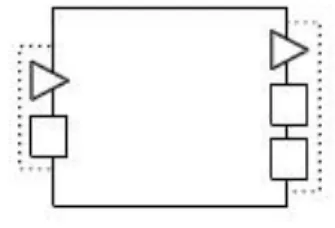
distinguish between these concepts. In this thesis they will be considered different. By component model we shall mean a set of well defined standards and conventions for a component. More specifically, a component model defines what a component is and how it interacts with other components. In order for a group of components to work together it is necessary for them to be compliant to the same component model. On the other hand a component framework is a concrete technical solution. It allows components compliant to a given component model to work together. Bachman et al. liken a component framework to a mini-operating system, because it manages resources shared by components, and provides the mechanisms for their communication just like an operating system does with processes [17]. Figure 1 brings all the CBSE notions previously described together and shows how a typical component based system is organized.
- 9 - Background of the general comparison As depicted in Figure 1 a component framework provides the technical means for components to work together. Crnkovic and Larsson liken a component framework to a circuit board in whose positions components are inserted [15]. The component model defines the requirements for a component which is to be deployed in the framework. Each component defines its incoming and outgoing interfaces. All incoming interfaces of a component must be resolved before it is successfully composed into a framework.
A subfield of CBSE that is being actively worked on is component system modeling. Its aim is to create simplified representations (models) of the components and their interactions. Different modeling formalisms have been defined for the purpose. Component system models usually describe the whole architecture of the component system under consideration, but often can be used to describe lower level designs as well. It can be argued that modeling is not an integral part of CBSE, since none of the popular definitions of CBSE mentions it and many popular component technologies provide no means for adequate and useful modeling. However, component modeling is an essential part of the component based development process. Practicing component based development without having at least coarse-grained models of the needed components and their interactions can be chaotic and poses a great risk for the whole project. Also, having such models allows for early evaluation of the system before it has been implemented. Hence, in the rest of the thesis component system modeling will be considered as an integral part of CBSE, though it is not yet a well established practice and there is little consensus about the modeling best practices in the context of CBSE.
- 10 - Background of the general comparison
3.2 Overview of model-driven development
As Selic emphasizes it is hard to imagine that a building or an automobile can be created without first creating a set of specialized system models [18]. Many software systems are much more complex than this and thus it seems logical that modeling techniques from other engineering disciplines are adopted in software development. That is what MDD tries to achieve. Models in MDD are used to reason about a problem domain and design a solution in the terms of that domain. In essence the philosophy of MDD is to start with models which are simple and include only the most essential parts of the designed system. Then typically these initial models undergo series of elaborating transformations until a final model is achieved. This final model actually is the target system itself and is the model with the lowest abstraction level.
Raising the level of abstraction in order to simplify software development has always been a primary goal in software engineering. An outstanding example for this is the transition from second-generation (assembly) languages to third-generation programming languages (3GL). 3GL languages are much more programmer-friendly and allow engineers to program agnostically of some non-essential, hardware specific details. MDD can be seen as another logical step in this direction. Usually when following a MDD approach the models are lacking any details unrelated to the system view being represented – not only the low-level hardware details as it is in 3GL. MDD promotes shifting the focus from code and programming constructs to abstract models throughout the whole development lifecycle, including documentation, requirements gathering and analysis, design, testing etc.
The term model has several different definitions and is a primary one in MDD. As to Beydeda et al. "a model is a set of statements about some system under study" [19]. Rahmani et al. augment this definition by defining a model as "a description or specification of a system and its environment for some certain purposes" [20]. The key idea that makes this definition more substantial than the first one is that a model is aimed at a few distinct purposes. Every model is meant to allow engineers to reason about and design the target system ignoring irrelevant details and focusing on the artifacts related to the purposes of the model. A variety of modeling concepts and notations may be used to emphasize on specific views and perspectives of the system, depending on what is considered relevant at some point. These concepts and notations are usually a part of the model formalism (or language), which defines the model's syntax and semantics [19]. Rothenberg captures well the essence of these
- 11 - Background of the general comparison definitions and the concept of modeling in general in his self-explanatory definition: "Modeling in its broadest sense is the cost-effective use of something in place of something else for some purpose. It allows us to use something that is simpler, safer, or cheaper than reality instead of reality for some purpose. A model represents reality for the given purpose; the model is an abstraction of reality in the sense that it cannot represent all aspects of reality. This allows us to deal with the world in a simplified manner, avoiding the complexity, danger and irreversibility of reality" [21].
When a complex system is being designed it is quite common to develop not just one, but a set of models. These models usually present different views to the system and might be at different levels of abstraction. It is often necessary to convert between the different models, or to create new ones based on the already existing models. This is achieved through transformations. A model transformation can be defined as an operation which takes as input a model of a system described in formalism F1 and produces another one described in
formalism F2. Transformations are also a primary notion in MDD and have been a subject of
many both theoretical and practical studies. Many different classifications of model transformations have been created over the years. In this section only a few of the most notable ones (also described by Beydeda et al. [19]) are presented.
A very simple distinction between transformations is based on the type of the input and output formalism. More specifically a transformation is called endogen if the formalism of its input model and the one of its output model are the same (F1 = F2). Otherwise it is called exogen (F1
≠ F2).
Another distinction can be based on the abstraction level of the input and output models. Transformations evolving the input model into an output model at the same level of abstraction as the input one are called horizontal. Ones which transform the input model into a model that is closer to the run-time platform (e.g. source code generation) are called
vertical.
Another important distinction is based on the amount of manual work needed for a transformation. In this respect a transformation can be classified as fully automatic, partially
automated or manual.
The last classification to mention is based on the technique used for the description and execution of a transformation. A declarative transformation is described by rules, which are
- 12 - Background of the general comparison specified by pre- and post-conditions. These pre- and post-conditions describe statements about the states of the input and output models which hold true respectively before and after a successful execution of a transformation. Transformations which define series of actions which should be taken to create the output model from the input one are called operational (or imperative).
So far the general idea and the most important notions of MDD have been described. However, nothing has been mentioned about how modeling fits in software development, and more specifically what have been the most notable practices. Beydeda et al. suggest a classification of the current MDD practices with respect to the ways models are synchronized with the source code [19]. Note that for the sake of simplicity in this classification it is not considered that source code itself is a system model, though it can be viewed this way.
Figure 2 The modeling spectrum [19].
Figure 2 shows the spectrum of modeling approaches with respect to such a classification. The distinct groups of practices are:
Code only - this approach considers the source code (usually written in a third-generation programming language) as the only representation of the system. If any separate modeling is done it is informal and intuitive. Obviously this approach is only adequate for small projects developed by very small teams or a single developer.
- 13 - Background of the general comparison
Code Visualization - this approach uses the source code itself as an initial representation over which transformations are applied. These transformations result in different visual representations of the code. These are used by the software engineers to better understand the code. Such transformations are usually fully automated.
Roundtrip Engineering takes the idea of Code Visualization one step further. Following this approach firstly a model is created, which is then transformed to source code or source code stubs, which are later manually implemented. Whenever a change is made to the code, the initial model is updated to reflect it. Thus it is guaranteed that the code and the model are always synchronized. Usually this approach is supported by a set of tools that automate the needed transformations between the code and the abstract model.
Model-centric. This approach requires that the models of the system are detailed enough so that the automatic generation of the full source code is possible.
Model only. In this approach models are used for design discussions and analysis, better understanding of business requirements, communication etc. Such models are usually not used in the actual implementation of the system.
The existence of so many MDD related practices shows that MDD defines a very general and abstract development approach, which allows different interpretations and unfortunately misinterpretations of its philosophy. In fact MDD defines no formal requirements as to how models and model transformations are described. Also it does not concisely define a development process. Thus there is a need for a set of development standards which augment the general idea of MDD. The most prominent such initiative is Model Driven Architecture (MDA) which is created and supported by OMG. MDA employs OMG’s established modeling standards like Unified Modeling Language (UML) [22] and Meta-Object Facility (MOF) [23] to define an open, vendor-neutral MDD based approach [19]. MDA defines the following types (layers) of models:
Computation Independent Models (CIM) - these are the initial type of models when following the MDA approach. The CIM models only represent the business context and business requirements.
- 14 - Background of the general comparison
Platform Independent Models (PIM) - a refinement of the CIM models. Specifies services and interfaces that the target systems must provide to the business. PIM models do not include any platform specific information.
Platform Specific Models (PSM) - a refinement of the PIM with respect to the chosen technological platform.
Implementation Specific Models (ISM) - the final source code of the system.
The models in each of these layers are elaborated to construct the models of the successive layer. Figure 3 shows how the layers correlate to each other and what kinds of models are typically included in each of them.
Figure 3 MDA layers and transformations [19].
MDA is the most popular MDD standard, but it has also been heavily criticized for being overly complex, too formal and requiring too much upfront investment in training. An alternative model-driven approach called Agile Model Driven Development (AMDD) has been introduced as a lightweight alternative to MDA. AMDD is aimed at incorporating better modeling into the agile software development, thus scaling it beyond its usual small and co-located team approach [24]. However, it can be argued that AMDD is not a true MDD approach since it discourages the constant usage of detailed models as main artifacts
- 15 - Background of the general comparison throughout the whole development lifecycle. AMDD promotes the usage of models which are only good enough to drive the overall development efforts. AMDD is becoming more and more popular in the context of the constantly growing interest in agile methodologies.
3.3 Method of comparison
There are two general approaches for comparing development paradigms. The first is a non structured one. Following this approach a comparison would typically be at a high-level and provide mostly theoretical and philosophical reflections on the common and different features of the paradigms. On the contrary, a structured comparison would require a clearly defined comparison method. Such a method would typically select important aspects of software development which are very much influenced by the used development paradigms. The comparison then would comprise of an in depth and justified considerations of how the targeted paradigms influence these aspects.
In this thesis an intermediate approach is taken. Firstly a systematic comparison method is introduced and motivated. Then this method is applied by discussing and comparing the influences of both CBSE and MDD over the selected aspects. These discussions and comparison are supported by references to established publications, practical case studies and where appropriate metrics. The comparison results are used as a basis for a brief and higher level comparison, which extracts the essence of the previous one and proposes ways for combining CBSE and MDD.
The method proposed in this thesis is based on a small, two-level hierarchy of what is called
comparison aspects. The first level of this hierarchy contains aspects correspondent to the
main activities in software development. The Requirements comparison aspect corresponds to the activities of requirements gathering and requirements analysis. The Design comparison aspect corresponds to all low-level and high-level design activities. The Development aspect corresponds to the activities of implementation, validation, verification, deployment and maintenance.
Besides these, the first level also contains comparison aspects related to the decision making whether a paradigm should be used or not. Such a decision usually depends on two types of factors - factors related to the business needs and ones related to the specifics of the
- 16 - Background of the general comparison organization developing the software. Thus the first hierarchy level also contains the following comparison aspects - Business specifics and Organizational specifics.
The comparison aspects from the first level are very general and it is hard to directly compare development paradigms with respect to them. Thus each of them is further divided into more specific ones. Figure 4 shows the whole comparison aspects hierarchy in the form of a simple mind map. The following subsections list all comparison aspects and define the questions that should be answered in the process of applying the comparison method.
Figure 4 Hierarchy of comparison aspects
The method proposed herein is a general one and can be used to compare development approaches other than MDD and CBSE as well. Moreover it can be used to compare software engineering objects other than development approaches as well, by comparing them from the perspective of each aspect. This is because the comparison aspects defined by the method are general and are spanned in scope throughout the whole development process. This allows for systematic analysis of the impacts the objects under consideration have on the different phases of software development. Some of the considered objects may not interfere in any way with the matters implied by a comparison aspect and this should be as well taken into consideration when applying the method.
- 17 - Background of the general comparison
3.3.1 Business specifics
When discussing this top-level aspect the facts that make the approaches selected for comparison attractive or unattractive from a purely business point of view should be considered. Such a discussion should clarify what business needs does each of the considered approaches meet and what are the business threats posed by each of them. Also it should be reasoned about the appropriate contexts in which the paradigms can be used successfully, judging by the experiences and considered best practices. Follows a list of the sub-aspects and the questions to be considered when discussing them:
Drivers – What are the motivations and aims for the paradigms?
Maturity – For how long have the paradigms existed? What is the overall opinion of the practitioners? How many success stories do we know?
Target system specifics – What kind of systems (in terms of domain, size etc.) are usually built using these paradigms?
3.3.2 Requirements
The discussion of this aspect should encompass how flexible and convenient are the approaches regarding requirement specification and reaction to requirement changes. It should also consider the benefits of each of the selected approaches when it comes to requirements-to-design transformation. The sub-aspects to consider are:
Requirement specification – Do the paradigms help in modeling the initial requirements? If they help - how? Can the modeled requirements be easily used for a design?
Changing requirements - How flexible are the paradigms towards changing requirements?
3.3.3 Design
This top-level aspect implies a discussion on the different approaches to software design at all levels of granularity and abstraction when using the selected paradigms. Moreover the following sub-aspects should be considered:
- 18 - Background of the general comparison
Separation of concerns (SoC) - How is SoC achieved? What are the building blocks of SoC?
Architectural support - Do the paradigms help in describing architecture? If so - how? Is there anything that should be considered when creating the architecture for software that is to be built by using these paradigms?
Design for Extra-functional requirements - How do the paradigms deal with extra-functional requirements at design time?
Design & Architecture evaluation - What are the design best practices for these paradigms? Is there an easy way to evaluate a design and identify problems early?
Design reuse - If a design is once created using these paradigms is it possible to reuse it (even partially) for other systems?
3.3.4 Development
This top-level aspect implies a discussion encompassing all issues related to system development, verification, validation and maintenance. More specifically the following sub-aspects should be considered:
Required tools, technologies and their maturity - What kind of tools are required? How mature are these tools? Is it possible to avoid vendor lock-in?
Verification and Validation (V&V) - Are there some benefits or handicaps when verifying or validating software built using these paradigms?
Traceability, understandability and maintainability - How easy is it to understand a solution when using these paradigms? How maintainable are the built systems? How easily can a new team member "catch up"?
Dealing with legacy code - How legacy code can be encapsulated, so that new development can take place without having to modify it?
Code reuse - Can we build modules that can be reused in other systems? What is the price for such a reuse - glue code, adapters etc.?
3.3.5 Organizational specifics
This aspect implies a discussion on what an organization adopting the paradigm should take into consideration. Moreover the following sub-aspects should be considered:
- 19 - Background of the general comparison
Development methodologies - Are there any problems using these paradigms when working with the most popular development methodologies - waterfall, iterative approaches, agile approaches, RUP etc.?
Organizational requirements - Is there anything special about an organization that would like to use these paradigms? How mature should it be? What kind of in-house experience and know-how should it possess?
Team member qualification - What kind of qualification should the engineers have? How easy are the technologies and paradigms to adopt and learn?
Financial issues – Are the tools, technologies and employee trainings expensive? For how long does such an investment pay off?
- 20 - General comparison of CBSE and MDD
4 General comparison of CBSE and MDD
So far the backgrounds of CBSE and MDD have been summarized and a general comparison method has been introduced. The two paradigms are still areas of active research which tries to overcome (or at least to mitigate) their many open questions – e.g. dealing with extra-functional properties in CBSE and managing models versions. Being mostly a bottom-up approach CBSE hopefully can make use of many of the advantages that MDD provides and vice versa [5]. This makes the comparative analysis of the two paradigms a potential source of improvements. This section deals with one of the two main purposes of this thesis – the general comparison of CBSE and MDD. The comparison is focused on the theoretical properties of the two paradigms. However, the current technological state of affairs of both paradigms is also discussed in details. It even predominates when considering matters which are currently being actively researched and still there is no consensus about. For this purpose the previously defined general method is used and this section discusses all of its comparison aspects with respect to CBSE and MDD. The final subsection summarizes and analyzes the comparison results.
4.1 Business specifics
4.1.1 Drivers
The main business driver for CBSE is component reuse. Ideally a component should be relatively self-sustained and encapsulated and should implement a coherent set of functionalities. This allows for a component to be directly reused (or with a minimal adaptation) in many other systems. Obviously, this reduces the needed efforts for development, test and maintenance. Thus other drivers consequent of component reuse include reduced time-to-market, enhanced quality and simplified maintenance [11], [5]. MDD also facilitates reuse though at a different level. Some of the created models when following a MDD approach can be reused in other systems as well. However, reuse is not considered the most motivating factor to adopt MDD, though in certain cases it can be very beneficial as well – e.g. the reuse of Platform Independent Models (PIM) in MDA to implement a system in different platforms. The main driver for choosing MDD is considered
- 21 - General comparison of CBSE and MDD to be the ability to abstract away irrelevant details so as to design more easily. This also allows for early evaluation and correction of the chosen design approaches leading to reduced overall costs and efforts [5].
4.1.2 Maturity
It is considered that the notion of component reuse, which is paramount in CBSE, was introduced by Mcllroy [25] in 1968. However, it was only in the 1980s and the 1990s that the theory of CBSE started to evolve fast to what we know today. In the last decades dozens of CBSE related technologies have surfaced. There are CBSE technical solutions designed to be used when developing in the most popular third generation programming languages. Using component technologies like OSGI [26], Java Beans [27] and .Net [28] has become common in the development of almost all kinds of software. This comes to show that CBSE philosophy is now widely understood by practitioners and has proven itself in practice.
Unfortunately, the majority of the existing component technologies do not implement some of the theoretical achievements in the area. For example most such technologies only allow syntactic component specification, but do not allow for semantic or extra-functional ones. This can be attributed to the fact that components are often understood in different ways in academia and in industry. Practitioners tend to think of a component as a large reusable piece of software with complex internal structure that does not necessarily have interfaces well-understood in terms of semantics and extra-functional properties [15]. Another reason for this mismatch between theory and practice may be that these theoretical achievements are not adequate to the requirements to develop software within time and budget constraints which forces practitioners to resort to more informal methods. All these come to show that CBSE theory, technologies and practitioners still have a way to go before CBSE can be considered mature in its entirety.
The first formal approaches to data modeling were introduces in 1970's [29]. Among them are the highly successful Entity-Relationship (ER) model and Object Role Modeling (ORM). In 1995 UML emerged, and UML diagrams since then have become synonymous to models in the minds of many software developers. Indeed it is now quite common to use UML and ER diagrams in the development of large projects. However, practitioners' attitudes towards modeling (and UML in particular) are not uniform. There is a group of them (e.g. those practicing MDA) who consider that modeling with formalisms is a necessity for successful
- 22 - General comparison of CBSE and MDD software development. On the other hand MDD and more specifically MDA has been a subject to a lot of criticism for being too complex and difficult to use [29]. Many practitioners do not believe that an investment of both money and time in modeling training pays off and thus still a lot of software is developed only by coding. Very similar ideas have been expressed by advocates of the agile development principles and most notably by Ambler. However, MDD and agile principles are not mutually exclusive. Even though agilists are critical about MDA and UML, Ambler defines Agile Model Driven Development (AMDD) which is an agile version of MDD. AMDD advocates models which are "just barely good enough" to drive the overall development efforts [24].
All these different attitudes to modeling show that almost all practitioners value modeling to some extent, but MDD still has not proven indisputably to be a mature paradigm which defines a set of universal best practices.
4.1.3 Target system specifics
CBSE technologies have been used in the development of virtually all kinds of software. Outstanding examples of CBSE technologies used successfully in a wide range of applications are Java Beans and EJB. These technologies constitute the core of the Java Platform Enterprise Edition (Java EE) and are used throughout industry to implement web interfaces, transaction safety, messaging and persistence. Another example of a successful CBSE technology in the Java world is OSGI which has been used successfully by the following markets: enterprise, open source, mobile, telematics, SmartHome and E-Health [26]. A notable extension of the OSGI component model is the Eclipse platform [30] which has been widely used to build rich desktop applications like the Eclipse IDE itself.
CBSE has been put into practice even in domains where non-functional requirements are equally or even more important than the functional ones. Examples of this are the embedded and real-time systems. Traditionally such applications are developed in an assembler or in C [15]. CBSE is usually avoided for such systems since most of the existing component based technologies do not allow specifying the non-functional attributes of the components. There are some developments like ProCom and Cadena which bring CBSE to the development of such systems. OSGI is also being developed to accommodate such changes by the Vehicle Expert Group (VEG) [31]. Then again, CBSE is still not considered the method of choice
- 23 - General comparison of CBSE and MDD when developing such systems, even though methods for applying component based technologies in these domains are being actively researched.
CBSE is usually a sane method of choice when developing a product line of software products. Well designed components are ideal subjects for proactive, systematic, planned, and organized reuse. Crnkovic and Larsson discuss the advantages that the component approach has compared to alternatives like using libraries or OO frameworks for building product lines [15]. Some component models have been designed especially for the purpose of developing product lines. One notable such model is Koala [32] which is used by Philips software architects and engineers to develop a product population for mid- and high-range TV sets. Almost every medium-sized or large software project involves some modeling, even if it is for example something as simple as a small UML use case diagram. MDD approaches can be used in every project and it is hard to say what makes a project suitable for such an approach. The opinions of the researchers and practitioners range from the idea that MDD is an absolute necessity for successful software development, to complete denial of modeling as a useful activity. It is usually up to the "taste" of the practitioners to decide whether or not to use MDD or its refinements (like AMDD and MDA) for a given project. It is however reasonable to suggest that the need for software models is proportional to the complexity and size of the target application, since MDD targets to reduce design complexity in first place.
4.2 Requirements
4.2.1 Requirement specification
Unclear and ambiguous requirements are among the main risks for CBSE [15]. In order to select or design and implement the appropriate components it is a prerequisite that the correct functional and nonfunctional requirements are known. A component based technology may provide a way for modeling requirements. However, this is often not the case and most such technologies do not provide any mean for the requirements analysis of the whole system being developed. Thus CBSE is usually augmented with techniques for requirement engineering. On the other hand MDD provides suitable ways for the modeling and specification of requirements. MDD tries to tackle development complexity by raising the abstraction level
- 24 - General comparison of CBSE and MDD higher than the level of technical details and closer to the application domain. This allows expressing the requirements easily in a way which is close to the application domain.
When using MDD the initial models usually represent a formalized expression of the requirements. These models are then transformed multiple times until a fully functional system is achieved. An outstanding example for a modeling technique that allows specifying requirements are the UML use case diagrams. They are used to model the functionality provided by a system and are widely used in practice for business and requirements analysis. Other notable techniques used for modeling requirements are UML activity and state machine diagrams and BPMN [33].
4.2.2 Changing requirements
CBSE focuses on composition of components code and thus it is mainly a bottom-up approach. However, a requirement change usually imposes a "top-down" change in the software, meaning that a requirement change may imply architectural and design changes which then imply implementation changes. Such changes are hard to implement in bottom-up approaches since they do not provide traceability between requirements and implementation artifacts like components. Thus after a requirement change is introduced an analysis should be carried to evaluate which components should be replaced or adapted.
Another major problem with changing requirements in CBSE is the cyclical requirement-component dependency (CRCD) introduced by Tran et al. [34]. In brief, this cyclical dependency constitutes of the following:
1. Reexamination of a set of previously selected components. This usually happens after the creation or modification of a system requirement. In the worst case, the reexamination leads to the evaluation and selection of new components, which is a lengthy and laborious process.
2. Reexamination of associated requirements. The replacement of a set of components often leads to lack of proper support for some existing system requirements implemented by them. Such problems are usually discovered during the integration or at the worst during later phases. These problems lead to reevaluation and re-negotiation of these system requirements to ensure timely delivery, which then leads to the reexamination of a set of previously selected components (step 1).
- 25 - General comparison of CBSE and MDD Tran et al. suggest strategies for the mitigation of the effects of CRDC like Ensuring appropriate support for early component evaluation and Prioritizing system requirements. Still CRDC remains a key problem in CBSE that has not yet been adequately addressed [34]. A system being developed by adhering to the MDD approach usually observes very good traceability between requirements and implementation artifacts (e.g. source code). This is because each model, except for those created from scratch, is achieved by transforming others. Thus the relations between models representing system requirements and low-level models, which are close in nature to the implementation artifacts, are clear and it is straightforward to assess the impact and needed efforts.
Ideally, whenever a system requirement is added or changed then the models directly representing it should be modified to facilitate the change. After that the corresponding model transformations should be reapplied resulting in a new version of the system implementing the changed requirements. Thus the actual efforts needed for the implementation of a requirement change depends on the level of automation of the used transformations. If all transformations are fully automatic then only the changes in the initial models need to be manually applied. On the other hand, if no suitable transformation tools are available then there might be a lot of efforts needed for the propagation of a change to the low-level models. Hence the ease of implementing a requirement change depends on the quality and the level of automation of the available tools for model transformations.
4.3 Design
4.3.1 Separation of concerns (SoC)
Separation of concerns (SoC) is a paramount concept in software engineering. The introduction of the term is often attributed to Dijkstra [35], even though the ideas of SoC have been incorporated in software engineering before that.
In essence, SoC in software engineering refers to the separation of a software system into
elements that correlate with each other. Ideally, these elements should have exclusivity and
singularity of purpose, meaning that no element should share in the responsibilities of another or encompass unrelated responsibilities. The area of interest with which one of these elements deals is called a concern. Implementing SoC leads to more stable, extensible and
- 26 - General comparison of CBSE and MDD maintainable systems which observe less duplication and allow for reuse of modules across other systems [36]. SoC is usually achieved through boundaries delineating a given set of responsibilities. Some examples of boundaries for the definition of core behavior would include the use of methods, objects, components, and services [36].
Clearly in CBSE the software elements (building blocks), as defined by SoC, are the components. Component interfaces can be seen as the boundaries between the components, delineating components’ responsibilities and functionalities. CBSE allows software engineers to enforce SoC in a much more coarse-grained way than third generation programming languages do – by functions, classes etc. Thus components are usually subjects to SoC themselves, meaning that they are further divided into functions, classes or subcomponents. The main objects of work in MDD are the different models of the system being developed, but not modules constituting the system, as it is in CBSE. Thus SoC elements and boundaries in MDD are not that apparent as they are in CBSE. Actually MDD does not define explicitly how SoC is achieved. Once again approaches, augmenting the core MDD ideas have been defined for the purpose. These approaches implement SoC over the models of the target system rather than the system itself. An example for this is the MADE approach proposed by Beydeda et al. [19]. It suggests specifying individual concerns at all model levels including documentation, test code, and if possible deployment information.
4.3.2 Architectural support
Architecture of a software system can be defined as "...the structure or structures of the system, which comprise software elements, the externally visible properties of those elements, and the relationships among them" [37]. It is intuitive to liken components to the software elements and interfaces to the sets of their externally visible properties from the previous definition.
Software architecture and software components are complementary to each other. While the software architecture defines the elements (in case of CBSE - the components) that make up the system, it is the components that provide the needed properties and functionality. Moreover, software architecture focuses on the early design phases when the overall structure is designed to satisfy functional and non-functional requirements. On the contrary component technologies are focused on composition and deployment, closer to or at execution time. In
- 27 - General comparison of CBSE and MDD many component-based systems the architecture is visible even at runtime, since the system comprises the distinct components defined in the architecture [15]. Exceptions to this are technologies that perform code optimizations, which result in indistinguishable components at run time. Examples for this can be seen in the embedded systems domain - e.g. ProCom [11]. As mentioned a component technology may allow modeling of system architecture. The survey by Feljan et al. [38], reports on the properties of 22 component models, of which only 5 do not facilitate modeling. This comes to show that most current component technologies allow for architecture definition. However, there are no widely accepted component system modeling formalisms, which may eventually lead to vendor lock-in. Also most of the existing technologies only use specifically designed for their purposes modeling formalism thus constraining designers and architects in terms of expressiveness. In addition this reduces the ability to communicate architectural decisions since fellow designers, architects and developers may not be acquainted with these technology-specific formalisms.
The use of component technologies often constrains the architectural freedom. An architect might have only a limited set of available components to use. Thus the architecture should be defined in a way that uses only available components or custom made components, in case that the time and budget constraints allow for component development. Moreover, for many of the already existing components (especially for the commercial ones) the source code is not available and the APIs are not informative enough to foresee their actual behavior and potential integration problems. This complicates the tasks of evaluating and selecting appropriate components. Obviously, a successful architecture created under such constraints may not be possible for all cases.
MDD approaches are especially suitable for documenting architectures. Perhaps the most important concept related to architecture documentation is the view. A view of software architecture can be defined as "a representation of a coherent set of architectural elements, as written by and read by system stakeholders" [37]. A model was previously defined as "a description or specification of a system and its environment for some certain purposes" [20]. These definitions come to show that architectural views are in fact types of models, since a view is indeed a specification of a system and its environment for the purpose of representing a system from the perspective of a given set of stakeholders. Thus it is not surprising that approaches from MDD are widely used for describing software architectures. Today the Unified Modeling Language (UML) [39] is considered as the de facto standard notation for
![Figure 1 Design of a typical component based system [15].](https://thumb-eu.123doks.com/thumbv2/5dokorg/4729609.125107/15.892.173.714.105.461/figure-design-typical-component-based.webp)
![Figure 2 The modeling spectrum [19].](https://thumb-eu.123doks.com/thumbv2/5dokorg/4729609.125107/18.892.106.777.487.906/figure-the-modeling-spectrum.webp)
![Figure 3 MDA layers and transformations [19].](https://thumb-eu.123doks.com/thumbv2/5dokorg/4729609.125107/20.892.411.781.420.867/figure-mda-layers-and-transformations.webp)

![Figure 5 Statistics from an online interview on CBSE inhibitors by SEI [58].](https://thumb-eu.123doks.com/thumbv2/5dokorg/4729609.125107/46.892.106.780.594.1003/figure-statistics-online-interview-cbse-inhibitors-sei.webp)
![Figure 6 External view of a subsystem with three input message ports and two output message ports [4]](https://thumb-eu.123doks.com/thumbv2/5dokorg/4729609.125107/57.892.357.532.726.857/figure-external-subsystem-input-message-ports-output-message.webp)
![Figure 7 Subsystems and a message channel [4].](https://thumb-eu.123doks.com/thumbv2/5dokorg/4729609.125107/58.892.210.681.109.328/figure-subsystems-message-channel.webp)
![Figure 10 A component with two services - S1 with two output groups and S2 with single output group [4]](https://thumb-eu.123doks.com/thumbv2/5dokorg/4729609.125107/60.892.363.525.480.774/figure-component-services-output-groups-single-output-group.webp)
