This is the published version of a paper published in Computer-Aided Design and
Applications.
Citation for the original published paper (version of record):
Heikkinen, T., Stolt, R., Elgh, F. (2020)
Incorporating Design for Additive Manufacturing in Multidisciplinary Design
Automation – Challenges Identified
Computer-Aided Design and Applications, 17(5): 936-947
https://doi.org/10.14733/cadaps.2020.936-947
Access to the published version may require subscription.
N.B. When citing this work, cite the original published paper.
Permanent link to this version:
Computer-Aided Design & Applications, 17(5), 2020, 936-947 © 2020 CAD Solutions, LLC, http://www.cad-journal.net
Incorporating Design for Additive Manufacturing in
Multidisciplinary Design Automation – Challenges Identified
Tim Heikkinen1 , Roland Stolt2 and Fredrik Elgh3 1Jönköping University, tim.heikkinen@ju.se
2Jönköping University, roland.stolt@ju.se 3Jönköping University, fredrik.elgh@ju.se
Corresponding author: Tim Heikkinen, tim.heikkinen@ju.se
Abstract. One interesting method to take advantage of the particular capabilities
of Additive Manufacturing is to utilize a combination of lattice-structures and topology optimization. This paper presents the results and experiences from attempting to incorporate these in an existing multidisciplinary design automation system within the aerospace industry. A combined state of art and practice is outlined with discussions regarding challenges in current commercial CAD tools, multidisciplinary design automation, and with respect to aerospace requirements.
Keywords: Design for Additive Manufacture, Multidisciplinary Design Automation,
Lattice-based structural Topology Optimization
DOI: https://doi.org/10.14733/cadaps.2020.936-947 1 INTRODUCTION
Additive manufacturing (AM) has been defined in the standard ISO/ASTM 52900:2015 as a “process of joining materials to make parts from 3D model data, usually layer upon layer, as opposed to subtractive manufacturing and formative manufacturing methodologies” for which at least seven process categories have been identified. The opportunities or potential of AM span several fields of research and industries, for instance as outlined by [28] design opportunities range from part consolidation, using multiple materials, custom coloring, freeform geometry, cost effective customization, custom alloys and composites, cellular materials, and functionally graded materials.
However, AM is still in its infancy and there are several challenges to address, such as: CAD and digitalization where complete digital models are required, and the possible organic and small-scale optimized models are difficult to represent in current CAD-tools; production preparation is challenging because discretization, build patterns, and build orientations introduce boundaries between lines, surfaces, and layers which result in surface roughness and material anisotropy; support structures are required to compensate for loads due to gravity and temperature differences; each specific process technique and even machine capability is different which limits the material types, possibility to have embedded voids/structures, and process parameters
Computer-Aided Design & Applications, 17(5), 2020, 936-947 © 2020 CAD Solutions, LLC, http://www.cad-journal.net
possible to optimize; new verification, maintenance, repair, and recycling techniques are required for form surfaces, internal structures (e.g. lattices), voids (e.g. cooling channels), and functionally graded material; new cost models, including machine, material, labor, failures, transport, inventory etc. need to be established; and finally external and regulatory constraints are challenging due to the limited amount of historical data [28].
It is clear that design methods, guidelines, tools, and models are necessary to be able to effectively and efficiently take advantage of the opportunities presented by AM. Existing design theory and methodologies such as Design for Manufacture (DFM), Design for Assembly (DFA), and Design for Disassembly (DFD) have shown to lack especially with respect to capturing AM’s unique capabilities [30]. There seems to be a consensus that it isn’t enough to simply manufacture existing products with AM, but instead including some level of re-design as well [24], [28].
This paper presents the results from working in this direction by attempting to incorporate a Design for AM (DfAM) module in an existing multidisciplinary design automation system within the aerospace industry. The module consists of methods and models to utilize Lattice-based Structural Topology Optimization (LSTO) to synthesis AM specific solutions which could reduce weight, stiffen, and/or strengthen it by using a CAD integrated automation approach. A state of practice and art is first outlined followed by challenges identified in current commercial CAD tools, multidisciplinary design automation, and with respect to the requirements on aerospace components.
2 RESEARCH CONTEXT, FOCUS AND APPROACH
This work is part of a research project, called ProAct which is short for “Platform Models for Agile Product Development – Building an Ability to Adapt” where the main goal is to address “the need for new models, methods, knowledge and tools to build an ability to rapidly develop and adapt products when needs and requirements from different stakeholders rapidly change.”
In one of the case-companies addressed here there is currently an interest in AM, which potentially could directly reduce manufacturing costs, and in Topology Optimization (TO), which could help reduce weight. In the conceptual product development stages, the work is supported by an in-house developed multidisciplinary design automation system for the definition and analysis of large amounts of designs by varying geometry and environmental requirements (e.g. temperature) which can be used to find out how robust a design is with respect to stakeholder requirements. As an initial focus of this work, the objective was to formalize and incorporate DfAM methods and models within this system.
The project follows the Design Research Methodology (DRM) [4] which divides the research into four distinct phases; Research clarification, Descriptive study I, Prescriptive Study, and Descriptive Study II. The work presented here is part of a prescriptive phase where a combination of structured literature review and action research have been used to attempt and apply a state-of the-art modeling technique which takes AM’s particular strengths into consideration. The literature review was performed using the search engine Scopus (Scopus.com) focusing on TO, AM, and lattice using the following search term (?-sign is a wildcard representing any character): ("Additive manufacturing" or “3D printing”) and (“Topology optimization”) and (Lattice). To narrow down the search only papers written in English within Engineering, Material Science, and Computer Science fields were considered. Action research was applied by frequently working in the case-company and developing methods and models in close collaboration with the company experts.
3 RELATED WORK
3.1 Multidisciplinary Design Automation
Design automation is a process of formalizing and systematizing design processes that result in a system of pre-planned reusable assets. Design automation systems usually comprise computerized items that support engineers in a phase of a design process [16]. Design automation can be used
Computer-Aided Design & Applications, 17(5), 2020, 936-947 © 2020 CAD Solutions, LLC, http://www.cad-journal.net
to support efficient information handling and knowledge processing [11] in computer-based product modelling, as well as make possible new design exploration and optimization capabilities. It results in a collection of methods and models, which can come in the form of computer scripts, parametric CAD models, template spreadsheets, and so on. These methods and models are developed and maintained within the different disciplines involved and are dependent on each other through related product model constituents.
Knowledge-based engineering (KBE) systems are one type of design automation system. KBE is usually referred to as a method for the capture and reuse of product and process knowledge to automate repetitive tasks [25]. KBE utilizes knowledge-based system theory within the engineering field and the main difference between a conventional program is the separation of knowledge-base and inference mechanism. Configuration systems are another type of design automation system which assists design tasks where the objects involved are well understood and its main concern is to maintain consistency during a configuration task (make sure all constraints are satisfied) [1].
3.2 DfAM
DfAM is a concept used to describe the collection of design methodologies, procedures, methods, and tools specifically focusing on AM. It is rather difficult to discuss partially since AM is a collection of very different manufacturing technologies using different approaches for material deposition, recoating (if any), and bonding and is used to produce prototypes, complete end-use parts or assemblies, or for indirect production such as fixtures or tooling and they can be used to form hybrid processes (e.g. machining and inspecting layer by layer) or multi-stage processes (e.g. print on a formed component) [28].
AM design methodologies, procedures, methods, and tools have been extensively research on different levels of detail and focused on designers with varying levels of prior knowledge. There are several categorizations of DfAM research-focuses, such as: design assessment or design making [18], [20], opportunistic or restrictive [18], new or re-design [20], general or specific [30], generic, broadening, or specific [5], and concrete, quantification of effects on manufacture, and impact on design [28]. One way to categorize DfAM design tools are by file review processing software (processing e.g. scanned data), solid modelling systems, AM pre-processing software, and future AM systems such as topology optimization incorporated and cellular structure modelling systems [28]. For a completely successful transition toward AM the development of all these DfAM research focuses and design tools will need to be made.
3.3 LSTO
‘Lattice’ is a word which means different things depending on the specific context. One way to categorize lattice-structures are by its scale-level (see Figure 1); micro, meso, and macro [27]. Lattice-structures in this article are on the meso-scale and denote mainly three-dimensional periodic cellular structures (as defined in [3]). They have gained research interest the past at least two decades because of their excellent strength to weight ratio.
TO is a type of computational synthesis technique focusing on the optimal distribution of material in contrast to size or shape where geometric dimensions or the position of control vertices are optimized instead [23]. Historically, TO has been criticized for its almost organic geometric propositions which have been difficult or impossible to manufacture and the optimization has focused on the distribution of completely solid or void volumetric elements. When TO is combined with AM and lattice-structures, the material distribution results (usually in terms of relative density) from TO can be used to replace intermediate (not completely solid or void) volumetric elements with lattice-structures. Manufacturability can also be assured to some extent by focusing on the configuration of individual lattice-cells.
Computer-Aided Design & Applications, 17(5), 2020, 936-947 © 2020 CAD Solutions, LLC, http://www.cad-journal.net Figure 1: Scale levels of lattice structures, adopted from [27].
Incorporating lattice-structures based on TO can be done on different levels; macro and meso. On the macro-level, changes to the design space or boundaries where lattice-infill is allowed is optimized. This can be done using volumetric based TO methods, removing regions deemed unnecessary. On the meso-level the lattice-structure itself is optimized by looking at cell-shape and/or lattice-internal geometric dimensions. This is commonly done by using homogenization where the variations in relative density of the lattice-structure is related to some effective material property before TO since consideration of the meso-level details becomes too computationally expensive [2]. The optimization problem can be simplified by only allowing changes to one of the levels. If only meso-level changes are allowed the problem can be reduced to a size or shape optimization where the optimum relative densities are mapped to a pre-defined lattice pattern. Finally, some lattice structure TO methods incorporate feature positioning schemes as well. Below is a sample of different strategies and approaches found in a structured literature review:
• general strategies: [21], [27]
• only meso-level: [7], [9], [12], [13], [19] • meso and feature positioning: [8]
• only macro-level: [22]
• both meso and macro-level: [10], [29]
The strategy utilized in the work presented here is influenced by these but focuses only on meso-level LSTO and tries to take advantage of the approach with minimal modification to the original product. This is because the products investigated with the multidisciplinary design automation system are often highly integrated and fulfill many functional requirements. The idea is that if the designer identifies specific regions where weight might be possible to save and where there is optimally more space and few load-cases, the approach can be explored in parallel with the existing procedures.
4 CASE STUDY
The multidisciplinary design automation system addressed here is a distributed system where a shared model is used to communicate between geometric modelling and simulation. Figure 2 shows a general use-case process, first the design space to explore is defined in terms of design requirements and parameters, including their limits. These are used to generate a Design of Experiment (DoE) which specifies the designs which will need to be generated and analyzed to get an understanding of their correlations in order to evaluate for instance the robustness of the concept. From the project specification a system instance is then set up by choosing from different module methods and models, such as scripts for CAD-model configuration and automated meshing as well as template parametric CAD-models and load-cases. See [14] for a more comprehensive description.
The idea was to incorporate a DfAM module which utilized meso-level LSTO (more about this below) to a system instance utilizing programmed features which refer to geometric objects (e.g. load interfaces, constraint interfaces, optimization regions) and saves all other information (e.g. number of lattice-cells, relative density limits) within it. Then, using template pre-processor scripts and a standardized geometric representation a TO model would be created, executed, and the results retrieved in parallel to the existing procedure. During the system instance setup, the
Computer-Aided Design & Applications, 17(5), 2020, 936-947 © 2020 CAD Solutions, LLC, http://www.cad-journal.net
specific lattice type, size, relative density limits and configuration would be modelled and/or defined (see example in section 4.2). During execution the TO results would be used to calculate theoretical weight savings and to configure the lattice-structures according to the relative density maps (see example in section 4.3). Finally, a meshable geometry (using either 1D, 2D, or 3D elements) would be offered to analyze all design variants (with and without lattice-structures) according to the level of fidelity required and time as well as resources available.
Figure 2: Multidisciplinary design automation process overview with suggested DfAM module
integration (outlined section).
4.1 Case Example
The case-example involved a sector of a Turbine Rear Structure (TRS) designed to be manufactured using Selective Laser Melting (SLM), a powder-based AM technique which is well suited for lattice-structure manufacturing [6]. The TRS is a component within engines of commercial airliners and helps to de-swirl the gas-flow and works as a connection to the wing. To test the proposed method a simplified sector was filled with three different types of lattice; gyroid, square honeycomb, and center-supported cubic lattices (see Figure 3). The center-supported cubic lattice was then configured according to the results from Solid Isotropic Material with Penalization (SIMP) TO with the following settings: objective to minimize energy stiffness measure, volume constraint set to 50% of the original, relative volume between 0.2 and 0.8, and penalization factor P=1 using Abaqus ToscaTM. The reasoning behind the choice and placement of lattice-structures
was somewhat arbitrary but focused on thick sections where reduced weight might be possible. The higher specific strength of the gyroid was utilized in the connection to the wing and the higher
Computer-Aided Design & Applications, 17(5), 2020, 936-947 © 2020 CAD Solutions, LLC, http://www.cad-journal.net
specific stiffness of honeycomb and center-supported cube lattices within the blade and hub sections. All surfaces which were in direct contact with the gas-flow was disregarded.
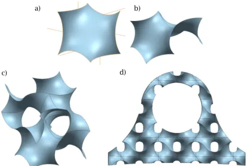
Figure 3: Three different example lattices integrated into the simplified TRS sector: (a) original
TRS sector, (b) gyroid-lattice, (c) square honeycomb, and (d) center-supported cube.
4.2 Modelling of Lattice-structures
One effective approach to model a gyroid-lattice found in literature is to plot iso-surfaces of an approximated implicit function which can then be used to export STL-files for printing or simulation [19]. Within different forums and videos found on the internet there are several approaches to model them using NURBS-based CAD-systems but there seems to always be an issue getting tangential interfaces between the cell-boundaries. For the purpose of this prototype a parametric gyroid was wanted using the CAD-system available and without getting a completely STL-based model which would be difficult to use downstream. The gyroid was built using the Fill-surface feature in Siemens NXTM with six arcs and a tangential constraint in the middle of each toward the
connecting gyroid cell (see Figure 4). The results using this approach are quite significantly different from a perfect gyroid but worked well enough for the purpose of this prototype. A large enough rectangle was then modelled and cut into the required shape. The square honeycomb was simply modelled using iso-parametric curves on the internal face of the vane and extended as sheet-bodies.
a) b)
Computer-Aided Design & Applications, 17(5), 2020, 936-947 © 2020 CAD Solutions, LLC, http://www.cad-journal.net Figure 4: Gyroid modelling in feature-based CAD system: (a) base-element, (b)-(c) gyroid
configuration from copies of base-element, (d) gyroid configuration cut to shape.
A programmed feature, called Custom Feature in Siemens NXTM, was created for the
center-supported lattice structure which could then be attached to the CAD-model rebuild tree and updated according to any changes to referenced model entities. It could also be used to represent the lattice in different levels of fidelity, either 1D points and lines for faster modelling or 3D solids possible to export as STL-format for printing or any standardized geometric format (e.g. STEP, Parasolid, IGES) for downstream analysis tasks. The center-supported lattice structure could follow the curvature of the face and was not applied to any holes in the face, see example 1D representation in Figures 3(d) and 5 as well as 3D in Figures 6, 7(b) and 8.
Packaging the information (see Figures 5 and 6(a)) required to configure and execute the LSTO DfAM module as a programmed feature object made it easier to ensure that there was no interaction with other components and without much effort a user-friendly graphical user-interface could also be provided which was thought to make it easier to share as well as maintenance (see user-interface in Figure 6(b)).
Figure 5: Center-supported cube lattice example (5 and 3 instances in U and V-direction
respectively and 2 levels with 5mm distance between levels).
a) b)
d) c)
Computer-Aided Design & Applications, 17(5), 2020, 936-947 © 2020 CAD Solutions, LLC, http://www.cad-journal.net Figure 6: Integration of center-supported lattice cube, from left to right: (a) information model,
(b) programmed feature user interface.
4.3 Automated Procedure
During execution a STEP-file was first exported and the information from the programmed feature was used to configure an AbaqusTM script by creating an instance of a script-template and updating
all the current configurations unique settings (such as path of STEP-file, coordinates for lattice design space and non-design space) using an extended script language following the convention presented in [17] (see example in Figure 8).
The script was then executed and the relative density from the results were used to configure the lattice dimensions between given min and max diameters (dmin and dmax) by finding the closest
FE-nodes relative density to a struts or nodes center and setting the diameter proportional to that with a simple linear model which gives dmin for ᴩmin and dmax for ᴩmax (see Figures 7 and 8).
Figure 7: Center-supported cube lattice examples, from left to right: min and max diameter set to
(a) 0.8mm and 2mm (b) 0.4mm and 1mm. LSTO feature
Lattice type Design space Non-design space
Relative density limits (min, max) Relative density map
Center-supported cube on Face Face
Instances (U and V-direction) Levels
Distance between levels Diameter limits Nodes Struts
Model nodes and struts Get diameter (from relative density)
Computer-Aided Design & Applications, 17(5), 2020, 936-947 © 2020 CAD Solutions, LLC, http://www.cad-journal.net
stepFile = @STEPFILE@ resultRelativeDensityFileName = @RESULTFILE@ latticeSpaceFindAtCoord = @LATTICE_COORDINATE@ nonLatticeFindAtCoord = @NONLATTICE_COORDINATE@ ... ... stepFile = 'Sector-Flexible_DC_1.stp' resultRelativeDensityFileName = DENSITY_MAP.csv' latticeSpaceFindAtCoord = (4, 45, -15) nonLatticeFindAtCoord = (3, 37, 94) ... Relative density map Configure lattice dimensions Topology Optimization
Variant model with homogenous lattice-structures
Variant CAD-model with (compliance) optimized lattice-structure Configure TO-script
Execute TO-script
Figure 8: Executive part of proposed DfAM module (see overview in Figure 2) where the modelled
center-supported lattice structure is configured according to the relative density results from TO.
5 IDENTIFIED CHALLENGES
Incorporating a DfAM module which consists of methods and models for meso-level LSTO presented several challenges using current CAD-tools as well as specifically due to the multitude of disciplines involved with the studies and the strict requirements on aerospace components. Below are separate sections addressing these points.
5.1 Challenges Related to Current CAD-tools
During the case-example development it was clear that the feature-based CAD-tool (Siemens NXTM) used at the case-company did not have adequate feature support for lattice-structure
Computer-Aided Design & Applications, 17(5), 2020, 936-947 © 2020 CAD Solutions, LLC, http://www.cad-journal.net
modelling. In the latest releases some initial support has been added to model and configure lattice-structures according to TO-results, but without the capability to export the lattice-structures in a format which can be used effectively downstream and without the capability to customize the structures further (e.g. adding additional support to the outer-most layers) they are of limited use. In addition, some lattice structures such as the Gyroid may require the possibility to model with implicit functions.
The structures need to have light-weight representations (e.g. STL) when modelling, the capability to export in mathematically sound formats (e.g. STEP, Parasolid) when sharing with downstream disciplines, as well as the ability to further model upon. Another CAD-tool investigated during this work was ANSYS SpaceClaimTM which also has a module with the capability to model
and configure lattice-structures according to TO. Similarly, however, the model is based upon STL which makes it difficult to use for e.g. analysis. Development of these modeling techniques are rapidly evolving, however. The approach applied in the case-example was to take advantage of the NXOpen API provided by Siemens NX and model using 1D and 2D geometric elements (points, lines, and surfaces) and only transform into 3D for either printing, visualization, or complete analysis.
5.2 Challenges Related to Multidisciplinary Design Automation
Multidisciplinary design automation introduced additional challenges since each discipline involved is highly dependent on the geometry and the CAD-model is often used as a carrier of information for many downstream activities [15]. In the case-example presented above the intent was to enable LSTO without affecting the established information flow. Multidisciplinary information in the current system is attached to the CAD-model using a naming convention applied to names and additional attributes of geometric entities as well as additional geometric elements which can be used to for instance convey positions. In the case-example, programmed features were used instead which utilize the CAD-systems referencing functionality and all the necessary information is embedded in this separate custom object or saved externally and then the paths are saved within it. This made it easier to identify and remove all the features which had been added during execution and is thought to simplify the sharing and maintenance of the method.
5.3 Challenges Related to Aerospace
The case-example presented here is far from meeting the tough requirements within the aerospace industry mainly due to a lack of AM-specific meso-level material models, life-analysis methods, and inspection methods. AM material models are highly anisotropic and depend on many product and process specific parameters such as build orientation, thickness variations, build angles, print patterns, etc. Predicting meso-level attributes does not make this any easier. There are several research efforts focusing on this however and their results in combination with internal testing and validation could be one interesting future research direction. Life-analysis is a particularly difficult analysis which relies on historical data and accurate behavioral models. Last, but maybe even more important is inspection. Some of the lattice-structures are difficult or even impossible to inspect in some cases using traditional approaches (look at the gyroid structure in the case-example for instance). Currently the TRS is inspected for cracks using Fluorescent Penetrant Inspection which requires tools to reach the different sections under investigation [26]. Either in-process (e.g. photographing each layer) or CT scan inspection are two interesting technologies to combat this issue.
6 CONCLUSIONS
Integrating DfAM through LSTO within multidisciplinary automation systems is interesting because the flexible lattice-materials can be automatically updated to conform to changing loads and might be a more material efficient approach to improve stiffness or strength compared to more general dimensions such as thickness. However, as identified in the work presented here it is challenging
Computer-Aided Design & Applications, 17(5), 2020, 936-947 © 2020 CAD Solutions, LLC, http://www.cad-journal.net
due to the increased number of detailed features requiring different representation for modelling, analysis, and manufacture, as well as the lack of historical data compared to other manufacturing technologies, and inspection techniques for internal structures, further emphasizing the importance of addressing them. It should be mentioned that there are rapidly evolving software tools and several research efforts working to combat these challenges.
Tim Heikkinen, http://orcid.org/0000-0002-9337-791X Roland Stolt, http://orcid.org/0000-0001-6278-2499 Fredrik Elgh, http://orcid.org/0000-0002-3677-8311
REFERENCES
[1] Aldanondo, M.; Vareilles, E.: Configuration for mass customization: How to extend product configuration towards requirements and process configuration, Journal of Intelligent Manufacturing, 19(5), 2008, 521–535. https://doi.org/10.1007/s10845-008-0135-z
[2] Arabnejad, S.; Pasini, D.: Mechanical properties of lattice materials via asymptotic homogenization and comparison with alternative homogenization methods, International
Journal of Mechanical Sciences, 77, 2013, 249–262.
https://doi.org/10.1016/j.ijmecsci.2013.10.003
[3] Azman, A. H.: Method for Integration of Lattice Structures in Design for Additive Manufacturing, Ph.D. Thesis, Université Grenoble Alpes, 2017.
[4] Blessing, L. T. M.; Chakrabarti, A.: DRM, A Design Research Methodology, Springer, 2009.
https://doi.org/10.1007/978-1-84882-587-1
[5] Booth, J. W.; Alperovich, J.; Reid, T. N.; Ramani, K.: The Design for Additive Manufacturing Worksheet, 28th International Conference on Design Theory and Methodology, 139, 2017, V007T06A041. https://doi.org/10.1115/DETC2016-60407.
[6] Challis, V. J.; Xu, X.; Zhang, L. C.; Roberts, A. P.; Grotowski, J. F.; Sercombe, T. B.: High specific strength and stiffness structures produced using selective laser melting, Materials & Design, 63, 2014, 783–788. https://doi.org/10.1016/j.matdes.2014.05.064
[7] Chen, Y.: 3D Texture mapping for rapid manufacturing, Computer Aided Design & Application, 4(6), 2007, 761–771. https://doi.org/10.1080/16864360.2007.10738509
[8] Cheng, L.; Liu, J.; To, A. C.: Concurrent lattice infill with feature evolution optimization for additive manufactured heat conduction design, Structural and Multidisciplinary Optimization, 58(2), 2018, 511–535. https://doi.org/10.1007/s00158-018-1905-7
[9] Cheng, L.; Zhang, P.; Biyikli, E.; Bai, J.; Robbins J.; To A.: Efficient design optimization of variable-density cellular structures for additive manufacturing: Theory and experimental validation, Rapid Prototyping Journal, 23(4), 2017, 660–677. https://doi.org/10.1108/RPJ-04-2016-0069
[10] Chougrani, L.; Pernot, J. P.; Véron, P.; Abed S.: Parts internal structure definition using non-uniform patterned lattice optimization for mass reduction in additive manufacturing, Engineering with Computers, 35(1), 2018, 1–13. https://doi.org/10.1007/s00366-018-0598-2
[11] Elgh, F.: Computer-Supported Design for Producibility: Principles and Models for System Realisation and Utilisation, Ph.D. Thesis, 2007, Chalmers University of Technology.
[12] Gorguluarslan, R. M.; Gandhi, U. N.; Mandapati, R.; Choi, S. K.: Design and fabrication of periodic lattice-based cellular structures, Computer Aided Design & Application, 13(1), 2016, 50–62. https://doi.org/10.1080/16864360.2015.1059194
[13] Han, Y.; Lu, W. F.: A novel design method for nonuniform lattice structures based on topology optimization, Journal of Mechanical Design, 140(9), 2018, 091403.
Computer-Aided Design & Applications, 17(5), 2020, 936-947 © 2020 CAD Solutions, LLC, http://www.cad-journal.net
[14] Heikkinen, T.; Müller, J.: Multidisciplinary Analysis of Jet Engine Components: Development of Methods and Tools for Design Automatisation in a Multidisciplinary Context, Master Thesis, Jönköping University, 2015. http://urn.kb.se/resolve?urn=urn:nbn:se:hj:diva-27784
[15] Heikkinen, T.; Johansson, J.; Elgh, F.: Review of CAD-model capabilities and restrictions for multidisciplinary use, Computer-Aided Design and Applications, 15(4), 2018, 509-519.
https://doi.org/10.1080/16864360.2017.1419639
[16] Johansson, J.: Automated Computer Systems for Manufacturability Analyses and Tooling Design: Applied to the Rotary Draw Bending Process, Ph.D. Thesis, 2011, Chalmers University of Technology
[17] Johansson, J.: A feature and script-based integration of CAD and FEA to support design of variant rich products, Computer-Aided Design and Applications, 11(5), 2014, 552-559.
https://doi.org/10.1080/16864360.2014.902687
[18] Ko, H.; Moon, S. K.: Contrasting function with affordance in design for additive manufacturing, ASME Design Engineering Technical Conference, 2017.
https://doi.org/10.1115/DETC2017-68157
[19] Li, D.; Liao, W.; Dai, N.; Dong, G.; Tang, Y.; Xie, Y. M.: Optimal design and modeling of gyroid-based functionally graded cellular structures for additive manufacturing, Computer-Aided Design, 104, 2018, 87–99. https://doi.org/10.1016/j.cad.2018.06.003
[20] Oh, Y.; Zhou, C.; Behdad, S.: Part decomposition and assembly-based (Re) design for additive manufacturing: A review, Additive Manufacturing, 22, 2018, 230–242.
https://doi.org/10.1016/j.addma.2018.04.018.
[21] Panesar, A.; Abdi, M.; Hickman, D.; Ashcroft, I.: Strategies for functionally graded lattice structures derived using topology optimization for additive manufacturing, Additive Manufacturing, 19, 2018, 81–94. https://doi.org/10.1016/j.addma.2017.11.008
[22] Richards, H.; Liu, D.: Topology optimization of additively-manufactured lattice-reinforced penetrative warheads, 56th AIAA/ASCE/AHS/ASC Structures, Structural Dynamics, and Materials Conference, 2015, 1–15. https://doi.org/10.2514/6.2015-1430
[23] Rosen, D. W.: A review of synthesis methods for additive manufacturing, Virtual and Physical Prototyping, 11(4), 2016, 305–317. https://doi.org/10.1080/17452759.2016.1240208
[24] Rosen, D. W.: Research supporting principles for design for additive manufacturing, Virtual
and Physical Prototyping, 9(4), 2014, 225–232.
https://doi.org/10.1080/17452759.2014.951530
[25] Stokes, M.: Managing Engineering Knowledge, Professional Engineering Publishing Limited, 2001.
[26] Stolt, R.; Elgh, F.; Andersson P.: Design for inspection - evaluating the inspectability of aerospace components in the early stages of design, Procedia Manufacturing, 11, 2017, 1193–1199. https://doi.org/10.1016/j.promfg.2017.07.244
[27] Tamburrino, F.; Graziosi, S.; Bordegoni, M.: The design process of additively manufactured mesoscale lattice structures: a review, Journal of Computing and Information Science in Engineering, 18(4), 2018, 040801. https://doi.org/10.1115/1.4040131
[28] Thompson, M. K.; Moroni, G.; Vaneker, T.; Fadel, G.; Campbell, R. I.; Gibson, I.; Bernard, A.; Schulz, J.; Graf, O.; Ahuja, B.; Martina, F.: Design for Additive Manufacturing: Trends, opportunities, considerations, and constraints, CIRP Annals, 65(2), 2016, 737–760.
https://doi.org/10.1016/j.cirp.2016.05.004
[29] Wang, Y.; Zhang, L.; Daynes, S.; Zhang, H.; Feih, S.; Wang, M. Y.: Design of graded lattice structure with optimized mesostructures for additive manufacturing, Materials & Design, 142, 2018, 114–123. https://doi.org/10.1016/j.matdes.2018.01.011
[30] Yang, S.; Zhao, Y. F.: Additive manufacturing-enabled design theory and methodology: a critical review, International Journal of Advanced Manufacturing Technology, 80(1–4), 2015, 327–342. https://doi.org/10.1007/s00170-015-6994-5