Low-power Wireless Networks
Beshr Al Nahas
beshr@chalmers.se Chalmers University of Technology
Gothenburg, Sweden
Simon Duquennoy
simon.duquennoy@ri.se RISE SICS, Sweden Inria Lille - Nord Europe, France
Olaf Landsiedel
olafl@chalmers.se
Chalmers University of Technology Gothenburg, Sweden
ABSTRACT
In low-power wireless networking, new applications such as cooper-ative robots or industrial closed-loop control demand for network-wide consensus at low-latency and high reliability. Distributed consensus protocols is a mature field of research in a wired context, but has received little attention in low-power wireless settings. In this paper, we present A2: Agreement in the Air, a system that brings distributed consensus to low-power multi-hop networks. A2
introduces Synchrotron, a synchronous transmissions kernel that builds a robust mesh by exploiting the capture effect, frequency hopping with parallel channels, and link-layer security. A2builds on top of this reliable base layer and enables the two- and three-phase commit protocols, as well as network services such as group membership, hopping sequence distribution and re-keying.
We evaluate A2on four public testbeds with different deployment
densities and sizes. A2requires only 475 ms to complete a two-phase commit over 180 nodes. The resulting duty cycle is 0.5% for 1-minute intervals. We show that A2achieves zero losses end-to-end over long experiments, representing millions of data points. When adding controlled failures, we show that two-phase commit ensures transaction consistency in A2while three-phase commit provides liveness at the expense of inconsistency under specific failure scenarios.
CCS CONCEPTS
• Networks → Network protocol design; Sensor networks;
KEYWORDS
Consensus, Two-phase commit, Three-phase commit, Group mem-bership, Synchronous transmissions, Capture effect, WSN, IoT ACM Reference format:
Beshr Al Nahas, Simon Duquennoy, and Olaf Landsiedel. 2017. Network-wide Consensus Utilizing the Capture Effect in Low-power Wireless Net-works. In Proceedings of SenSys ’17, Delft, Netherlands, November 6–8, 2017, 14 pages.
DOI: 10.1145/3131672.3131685
1
INTRODUCTION
Context and Challenge Many applications in low-power wire-less networks build their operation on consensus: For example,
SenSys ’17, Delft, Netherlands
© 2017 Copyright held by the owner/author(s). Publication rights licensed to ACM. This is the author’s version of the work. It is posted here for your personal use. Not for redistribution. The definitive Version of Record was published in Proceedings of SenSys ’17, November 6–8, 2017, https://doi.org/10.1145/3131672.3131685.
networked cooperative robots and UAVs agree on maneuvers to ex-ecute [3]; wireless closed-loop control applications such as adaptive tunnel lighting [9] or industrial plants [46, 47] agree on set-points for actuators. Within the network stack, protocols need to agree on which cryptographic keys to use [13], which channel hopping and transmission schedules to follow [30], or which nodes to elect as cluster heads [61].
These application scenarios exhibit key differences when com-pared to traditional data collection or dissemination in wireless sensor networks: They demand primitives for network-wide con-sensus at low-latency and highly reliable data delivery with robust-ness to interference and channel dynamics [2]. For example, after rolling out new cryptographic keys or channel hopping schemes in a network, the new configuration can only be applied once a network-wide agreement has been reached that all nodes are aware of the new data. Otherwise, nodes might be excluded and would need to re-join the network.
Similarly, mission-critical applications such as cooperative robots need to achieve a consensus on which maneuvers to execute. For this, they do not only need to exchange position and velocity in-formation reliably between all nodes at low-latency but also need to know whether the information has been reliably received by all nodes before taking a coordinated action. Specifically, a node x cannot execute an action until it knows that all other nodes agree and in turn, they cannot execute until they know that x agrees with them. This requires multi-phase agreement protocols such as two-phase commit [26]. Protocols for distributed consensus are mature solutions in a wired context, such as for data centers or databases, but have received little attention in low-power wire-less settings. We argue that the low latency of new approaches to synchronous transmissions, such as Glossy [23] and Chaos [38], are key enablers for distributed consensus protocols in low-power wireless networks.
Approach In this paper, we tackle the challenge of achieving network-wide consensus in low-power wireless networks. We in-troduce A2: Agreement in the Air, which builds on a new syn-chronous transmission kernel, Synchrotron. Synchrotron extends the concepts introduced by Chaos with high-precision synchro-nization through VHT [53], with time-slotted operation, with a network-wide scheduler, with frequency hopping and multiple parallel channels, and with security features (in part inspired by LWB [21] and TSCH [17, 30]). On top of this robust base layer, we introduce a primitive for network-wide voting, a key component of consensus protocols in A2. We then tackle the consensus challenge
and show how to enable two- and three-phase commit protocols (2PC and 3PC) [26, 55] in low-power wireless settings. In addition, we address the consistent group membership problem and build
reliable primitives for nodes to join and leave the network. Appli-cations can use A2to reliably agree on, for example, cryptographic
keys, channel-hopping sequences or set-points for actuators, even in the presence of node or link failures.
Contributions This paper makes the following contributions: • We introduce network-wide voting, based on synchronous
transmissions;
• We build network-wide consensus protocols for low-power wireless: two- and three-phase commit;
• We devise a consistent group membership protocol based on network-wide transactions;
• We present Synchrotron, A2’s underlying kernel for syn-chronous transmissions, which provides distributed sched-ules, the ability to utilize multiple frequencies in parallel, and authentication and encryption to ensure robust and fast agreement;
• We implement and evaluate Synchrotron and A2on four testbeds ranging from 29 to 213 nodes. In our experiments, A2completes a 2PC round over 180 nodes within 475 ms
at low power. Synchrotron achieves zero losses end-to-end, over millions of data points. Moreover, we evaluate 2PC and 3PC’s liveness and consistency under emulated failures. OutlineWe provide the required background on consensus and the Chaos primitive in §2. In §3, we outline our primitive for network-wide voting and introduce two- and three-phase commit in A2. In §4,
we continue to design a group membership service for A2that lets nodes dynamically join and leave. In §5, we introduce Synchrotron, our underlying system architecture for synchronous transmissions. In §6, we evaluate A2and compare it to the state of the art. We discuss related work in §7 and conclude in §8.
2
BACKGROUND
This section introduces necessary background on the two- and three-phase commit protocols for consensus and on the Chaos communication primitive.
2.1
Consensus
Consensus is the problem of reaching agreement among several processes about a proposal, i.e., accept or decline it after a finite time of execution. Achieving consensus becomes challenging when faults may occur, that is, when communication is lossy and pro-cesses may crash. Two widely used, yet simple consensus protocols are two-phase commit (2PC) [26] and three-phase commit (3PC) [55]. We introduce both next and discuss their respective properties and limitations.
Two-phase commit (2PC) The protocol assumes the existence of one static coordinator and a set of participants, or cohort. As the name suggests, 2PC works in two phases: (a) Proposal Voting: the coordinator broadcasts a proposal to the cohort, each member replies with its vote, yes or no; (b) Decide: the coordinator decides to commit if the vote is yes unanimously; otherwise it decides to abort. It then broadcasts the decision to the cohort that will commit or abort upon receiving the message.
2PC is simple and comes at a low communication complexity, but has the major limitation of being a blocking protocol. Whenever
a node fails, other nodes will be waiting for its next message or acknowledgment indefinitely, i.e., the protocol may not terminate. Recovery schemes can be considered but fall short when it comes to handling two or more failing nodes. In particular, if the coordinator and a participant both fail during the second phase, other nodes might still be in uncertain state, i.e., have voted yes but not heard the decision from the coordinator. If all remaining nodes are uncertain, they are unable to make a safe decision as they do not know whether the failed nodes had committed or aborted.
Three-phase commit (3PC) Three-phase commit mitigates the above limitations by decoupling decision from commit. This is done with an additional pre-commit phase between the two phases of 2PC. The three phases are as follows: (a) Proposal Voting: same as in 2PC; (b) Pre-Commit (or abort): the coordinator and participants decide as in 2PC, but no commit is applied (abort is applied immediately); (c) Do Commit: participants finally commit. The additional phase guarantees that if any node is uncertain, then no node has proceeded to commit.
The protocol is non-blocking in the case of a single participant node failing: remaining nodes time out and recover independently (commit or abort). 3PC can also handle the failure of the coordinator and multiple nodes, by using a recovery scheme. Nodes will then en-ter the en-termination protocol, communicate and unanimously agree to commit, abort, or take over the coordination role and resume operation. In the more challenging case of a network partition, 3PC is, however, unable to maintain consistency.
2.2
The Chaos Primitive
Chaos is a primitive for network-wide, all-to-all dissemination, col-lection, and aggregation. Chaos operates in rounds where nodes send packets synchronously and receive data thanks to the capture effect[39]. In contrast to Glossy and LWB, nodes in Chaos syn-chronously send different data. At each reception, nodes apply a user-defined in-network aggregation function before sending again in the next slot, until completion of the round.
Synchronous transmissions and capture effect Chaos roots in approaches to synchronous transmissions, such as Glossy, where multiple nodes synchronously transmit the data they want to share. Nodes overhearing the concurrent transmissions receive one of them with high probability, due to the capture effect. For example, to achieve capture with IEEE 802.15.4 radios, nodes need to start transmitting within the duration of the preamble of 160µs [38]. Typically, in 802.15.4, the radio receives the stronger one of the synchronous transmissions if its signal is 3 dBm stronger, the so-called co-channel rejection. The exact capture threshold depends on the radio hardware and modulation schemes used.
In-network aggregationIn Chaos, each packet contains so-called progress flags, where one bit is assigned to each node in the network. The coordinator node starts a Chaos round by sending a packet with only its own flag set. Upon successful reception, a node sets its flag and merges the received packet with its own. It transmits in the next time slot when it received new information, i.e., new flags, or when it sees that a neighboring node is transmitting messages with fewer flags set, i.e., a neighbor knows less than the node itself. The process continues until all nodes have set their flag. Nodes then enter the so-called final flood phase in which each node transmits
Sleep / other Protocols,
e.g., RPL, … J
Agreement
(e.g., every 2 Min.)
A
C Collect(e.g., every 6 Min.) J Join(scheduled on demand) 1 2 3 4 5 6 7 8 9 10 Min. A A C A A A C A2Round T X Packet prep., TX/RX, processing R X 1 2 3 4 No de s A2Slot Radio on Figure 1:A2Overview:A2schedules rounds for network-wide con-sensus, dissemination, join, etc. as requested by the application(s). Each round has multiple slots in which nodes transmit, receive or sleep, driven by the transmission policy of the application. Between two rounds, nodes either sleep or are free to run other protocols, such as, for example, RPL.
the result multiple times to disseminate it before completing the round, i.e., turning off. In addition, a timeout mechanism ensures that the network-wide flood is kept alive by re-transmitting when the activity dies during a round.
The rules for merging are application specific. Chaos provides merging rules for network-wide dissemination and data collection. Moreover, it introduces user-defined aggregation functions (the function must be order-insensitive and idempotent). With the Max operation, for example, Chaos identifies the maximum value: Next to the flags, the only payload is the maximum value collected so far. Upon reception, nodes compute the maximum between their local value and the payload, write it to the packet payload, merge the flags, and set their flag before transmitting in the next time-slot. Chaos is no Consensus Protocol It is important to note that the progress flags set by the nodes throughout a round are not acknowl-edgment flags. They do not state the recipient of a particular packet; rather, they identify the nodes that contributed their knowledge to the current round. Hence, Chaos does not guarantee reliable reception as nodes may leave a round once they completed their final flood and they have no information whether other nodes also reached their final phase.
A2 builds on Chaos: It contributes a voting primitive on top
of which it builds consensus primitives and network membership services. A2also contributes at the lower layers, with Synchrotron,
exploiting multiple channels, synchronizing more efficiently and ensuring security. A2, however, inherits the scaling limitations from Chaos, as it requires a flag bit for each node in the network.
3
A
2: AGREEMENT IN THE AIR
A2proposes a set of network-wide communication primitives:
• Disseminate, Collect and Aggregateare the basic primitives, inherited from Chaos. Respectively, all nodes receive one value from the coordinator, all nodes receive one value from each node, all nodes receive one network-wide aggregate. • Voteis introduced by A2. Nodes vote for or against a
coor-dinator’s proposal. A B C Slot 1 A proposes 42 and votes for it
Slot 2 B votes for 42 Vo te s Va lu e Transmission Reception TX Success TX Failure Radio On -- - ? -- - ? -- - ? X-- 42 -X - 42 XX- 42 X X - 42 X X - 42 XX! 42 X X - 42 X X ! 42 XX! 42 X X ! 42 XX! 42 Slot 3 C votes against 42, completes Slot 4 B completes Slot 5 A completes A B C
XVote for a proposal
!Vote against a proposal
-Vote not (yet) received
Figure 2: Network-Wide Voting: A initiates a voting round in slot 1 and proposes the value 42. B votes for the proposed value in slot 2. C votes against the value in slot 3 and completes, B completes and relays the packet in slot 4, A completes and relays the packet in slot 5. For simplicity, we limit the final flood to one transmission.
• 2PCis introduced by A2. Enables network-wide agreement, with the drawback of being blocking.
• 3PCis introduced by A2. Enables network-wide agreement, non-blocking but can result in inconsistencies.
• Multi-phase protocolsare introduced by A2. Add reliability to Collect and Aggregate.
• Join and Leaveare introduced by A2. Provide consistent group membership.
We begin by introducing our network-wide voting primitive. Next, we combine it with dissemination and collection primitives as introduced by Chaos to devise protocols for network-wide agree-ment: two- and three-phase commit. In §4, we introduce a consistent group membership protocol which dynamically adds and removes participant nodes. A2schedules these primitives according to appli-cation requirements, allowing it to multiplex different appliappli-cations, as illustrated in Figure 1.
3.1
A Network-Wide Voting Primitive
We first address the challenge of network-wide voting – a crucial component of A2’s consensus primitives. The voting primitive col-lects votes from all participants for or against a proposed value. In practice, such a value represents, for example, the ID of an en-cryption key or a channel hopping sequence. All nodes that can commit to the proposal, because they, for example, have previously received the proposed key or hopping scheme, will vote for it. Any node that cannot commit votes against it. At the end of a successful voting round, the coordinating node is aware of which nodes voted for and against the proposal. For our discussion, we assume the existence of a group membership service within A2, i.e., that each node is aware of who else is participating and have been assigned a flag for voting. We introduce such a group membership service in §4.
Building on the concepts of Chaos, nodes share two pieces of information in each transmission: (a) The proposed value the nodes are voting on and (b) a list of votes representing for each node whether it already voted and whether the vote was for or against the proposal. The coordinator begins a round by proposing a value
to vote on and by voting for its own proposal, see Figure 2. Upon the first reception during a round, a node votes for or against the proposal and synchronously transmits its vote in the next time-slot. After voting, upon reception, a node merges the received information with any previously received votes of this round. It then transmits in the next time slot if it either (a) learned new information, to spread the new knowledge, or (b) received a packet with fewer votes than it is aware of, i.e., from a neighboring node having less information, aiming to help this neighbor to catch up. A node reaches completion when all votes are set in its local state. It then proceeds to the final flood stage, i.e., it transmits the final result repeatedly so as to aggressively distribute it in the network, as in Chaos. When a node does not receive for a few slots, a timeout triggers re-transmissions, for resilience to packet losses.
Our voting primitive, just as the original Chaos primitives, is best-effort in nature. As discussed in §2.2, when a round completes, the only guarantee is that all nodes contributed to the vote/payload. There is no guarantee that all nodes received the final vote/payload, as a node might, for example, fail right after voting but before re-ceiving any other node’s vote. To achieve network-wide agreement, we adapt the two- and three-phase commit protocols in §3.2 and §3.3.
3.2
Network-wide Agreement: 2PC
The two-phase commit protocol (2PC) is the simplest of the two consensus protocols we consider (c.f., §2.1). In A2, we achieve 2PC with two phases of synchronous transmissions back-to-back within a single round. First, in the voting phase, the coordinator proposes a value and collects the cohort’s votes. Second, in the commit or abort phase, it disseminates the outcome of the vote, i.e., commit if all agree, or abort otherwise. This is illustrated in Figure 3. Proposal Voting PhaseThe nodes vote for or against the proposal. The 2PC voting phase utilizes the voting primitive introduced in §3.1, but introduces a different termination criterion and behavior. Upon completing the first phase, nodes in the cohort, i.e., non coordinator nodes, do not leave the round as normal after final flood; instead, they continue to transmit the result at random slots ensuring that it spreads and reaches the coordinator eventually. Commit or Abort Phase Once the result of the voting phase reaches the coordinator, it decides to commit if and only if all nodes accepted the proposal; else, i.e., after a timeout or after receiving one or more votes against its proposal, it aborts. The coordinator spreads the decision using the network-wide dissemination primitive: It commits or aborts, resets the votes, and starts the new phase in the next slot. Upon reception, nodes switch to the new phase, set their flags, adopt the final result and continue the dissemination. This way, the two phases of voting and commit/abort are interleaved rather than strictly segregated, for efficiency.
Failure Handling in 2PC 2PC handles failures with timeout ac-tions or blocking, depending on the phase of the protocol they occurred in. When a node fails before voting yes or after voting no, the coordinator takes a timeout action and aborts the transaction. When it recovers later, the failed node in this stage can safely abort the transaction. Similarly, if a node times out after voting no, it can safely abort. However, if a node times out in the uncertain state, i.e., it voted yes but does not hear back from the coordinator, then it
shall block and execute a recovery mechanism later to learn about the outcome of this transaction. Note, a node can commit when it gets the order from the coordinator; i.e., it does not need to block until it is sure that all other nodes get it too. It is important to point out that no further commit can complete until all blocked nodes are recovered.
3.3
Network-wide Agreement: 3PC
To overcome the blocking nature of 2PC, where even single-node failures may result in non-termination (c.f., §2.1 and §3.2), we next introduce three-phase commit (3PC) for A2. In a nutshell, 3PC adds
a buffer state, pre-commit, between the voting and the commit phases, ensuring that no node commits while any other node is still uncertain, i.e., it did cast its vote but is still waiting for the coordinator’s decision. In A2, this results in three phases executed back-to-back in a round: one vote and two dissemination phases. Note that 3PC trades liveness at the expense safety as discussed in §2.1.
Proposal Voting Phase The first phase is identical to 2PC, we realize it in A2with our voting primitive. At the end of the phase, the
coordinator has collected all votes and decided whether to instruct all participants to commit or abort.
Pre-commit or Abort Phase Once the coordinator has received the votes from all nodes or timed out, it switches to the next phase: If all nodes voted for the proposal, it switches to pre-commit, i.e., to enter the prepared state. Otherwise, it switches to the abort state. The coordinator distributes this new state via the dissemination primitive.
Upon receiving pre-commit, nodes know that the cohort agreed to commit. They prepare for the commit, e.g., lock resources, but do not execute anything that cannot be rolled back. Should any cohort node or network failure occur from this point onward, a timeout will result in the node committing.
This phase uses the A2dissemination primitive: As nodes do
not have the option to decline entering prepared or entering abort after voting, no further voting is required. Throughout the round, the coordinator gets individual confirmation through the progress flags, and can hence check whether all nodes have received the information and have transitioned to the requested state, i.e., are all in prepared or abort. At the end of this phase, nodes exit the round if they were instructed to abort, else, they prepare for the final phase.
Do Commit PhaseThe third and final phase is the commit phase, triggering commit at every node. This phase only follows when all nodes decided to vote for the proposal, i.e., we entered pre-commit and not abort after the voting phase. The coordinator switches to this phase once it knows that all nodes have completed the pre-commit phase, i.e., moved all to the prepared state. In A2, we realize it as dissemination round like the previous pre-commit phase. As all nodes must have confirmed (through setting their flag) the pre-commitbefore entering this phase, there is a guarantee that no node is uncertain when nodes commit, a property that enables recovering from multi-node failures.
Failure Handling in 3PC We detail here how 3PC handles incon-sistencies through timeouts. If a node times out in proposal voting,
TX Success TX Failure Voting Phase
Transmission Reception
XVote for proposal
!Vote against proposal
-Vote not (yet) received
Commit / Abort Phase
A
B
C
Slot 1
A proposes 42 and votes for it
Slot 2 B votes for 42 Vo te s Va lu
e C votes againstSlot 3
42
Slot 4 Slot 5
All votes reach A, switches to Abort (disagreement) A B C -- -? ? -- -? ? -- -? ? Ph as e -X -V 42 X X -V42 -X -V 42 X--A 42 X X -V42 X X -V42 XX-V 42 X X !V 42 X X !V 42 XX!V 42 X X !V 42 X X !V 42 -X -A 42 XX-A 42 X X -A 42 X X -A 42 X X -A42 X X XA42 X X XA42 X XX A 42 X X XA 42 X XX A 42 Slot 6 B switches to Abort phase Slot 7 C switches to Abort phase, completes Slot 8
B completes A completesSlot 9
Figure 3: Two-phase commit: Node A proposes value 42 in slot 1. In slot 2, node B agrees by voting for it. In slot 3, node C disagrees by voting against the proposal. This result propagates back to the coordinator, who initiates phase two of 2PC, abort in this example, in slot 5. In the end of the second phase, all nodes have reached the consensus to abort. For simplicity, we limit the final flood to one transmission.
then it aborts. If a node times out after receiving commit, then it can safely commit. If the coordinator does not receive all flags of pre-commitafter a certain timeout, it concludes that a node has crashed before getting pre-commit, and sends abort to avoid inconsistency. Finally, if a cohort node times out after receiving pre-commit, it concludes that the coordinator crashed in pre-commit, and proceeds to commit. Nodes recovering from a crash are assumed to have a saved state to act on. A recovering node proceeds to commit if it is in pre-commit or commit state, otherwise (voting state) it aborts.
Inconsistencies can happen in the case of network failures, e.g., when a cohort node times out in pre-commit; thus, it proceeds to commit, while the coordinator does not receive its confirmation flag and orders the rest to abort.
3.4
Multi-Phase Protocols
Instead of voting for or against a proposal, some applications merely need to reliably collect values or aggregates from the network and take a coordinated action based on this knowledge. Here, we use a modified version of the two-phase design: In the first phase, we use the collection and aggregation primitives to collect the results from all nodes. Once the coordinator has received the final result, it switches to phase two to (a) ensure that no node turns off before the result has reached all and (b) instruct the nodes to take action. Next, we build on this multi-phase design to devise consistent group membership service in A2.
4
A
2SERVICES
Building on the primitives introduced in §3, this section introduces bootstrapping, the join and leave procedures, and services such as channel hopping sequence and key distribution.
4.1
Bootstrapping: Join Request
Nodes willing to join the network bootstrap by doing a channel scan. Whenever hearing an A2packet from any node, they synchro-nize to the network: From the packet header, they learn low-level parameters such as the length of the round, slot size, packet size, and when the next round is scheduled and its application type. Once they are synchronized, they start participating as forwarders only: Upon reception they transmit in the next time slot when they learned new information, i.e., they follow the transmission policy. They do not add own data, as they have not joined the network
yet. In addition, they set a single bit flag – the so-called join flag – in the packet header of their transmissions. Other nodes receiving this flag during a round also set it in all subsequent transmissions. This flag will eventually propagate in the network and reach the coordinator, which will schedule a join round, detailed next.
4.2
Join
The goal of the join operation is to (a) assign a flag index to each node, and (b) inform all existing nodes about the new setup. We realize the join operation as a two-phase protocol. In the first phase we collect the IDs of the new nodes, i.e., nodes wishing to join. The second phase is a dissemination phase in which we disseminate the flag indexes assigned to the joining nodes. The process is illustrated in Figure 4.
Collect Phase The first phase is an extended version of the data-collection primitive, designed to let non-joined nodes contribute to the payload. The coordinator begins the round in the first slot and, upon reception, a node that wishes to join adds its node ID to the list and transmits in the next slot. Already joined nodes set their flag to indicate that they participated, and merge their local state with the received packet. For deterministic merging, we simply sort the IDs added by the nodes wishing to join and eliminate duplicates. Once the list grows too large; i.e., all fields are occupied, the merge operation employs a tiebreaker: We let the highest IDs join by keeping them on the list. Other nodes have to wait for the next round. We are limited by the packet size of 802.15.4 of 127 bytes, and typically join up to 10 or 20 nodes per round. However, note that the recent 802.15.4g standard supports packets up to 2kB in certain contexts [30].
Disseminate Phase Since we do not know how many nodes are aiming to join within a particular round, the coordinator cannot – in contrast to the previously discussed primitives – use the progress flags to determine when to switch to the dissemination phase, as flags are only assigned to the already joined nodes. Instead, the coordinator switches to the next phase if (a) the node IDs list is full or (b) it does not receive any further updates for a number of slots and the message has propagated through the whole (known) network and back; i.e., all progress flags are set, indicating that all joined nodes have seen it.
When committing on the new nodes, the coordinator assigns a flag index to each new node, registers it in the node list, and starts
A B C Slot 1 A begins Collection Phase Slot 2 Fl a g s Jo in in g N o d e Slot 3 C adds its ID to the packet Slot 4 Slot 5 A rec. C’s node ID assigns flag 3, switches
to dissemination A B - Ph a se B switches to Slot 6 dissemination Slot 7 C receives flag 3, confirms, switches to dissemination, completes Slot 8 B completes Slot 9 A completes -- - 1? ? A ssi g n e d in d e x X X 1 - - -X 1 - - -TX Success TX Failure 1: Collection Phase Transmission Reception XParticipated
- Not (yet) participated
2: Dissemination Phase -- - 1? ? -- - 1? ? -X 1 - -X 1 - - XX 1 - -X X 1 - -X X 1 - -X X 1 - -X X 1C -X X 1C -X X 1C -X X 1C -X X 1C -X - 2C 3 -X - 2C 3 X X - 2C 3 X X - 2C 3 X X - 2C 3 X X - 2C 3 X X X 2C 3 X X X 2C 3 X X X 2C 3 X X X 2C 3 X X X 2C 3
Figure 4: Membership Service: Join. In this example, nodes A and B have already joined and node C wishes to join. Thus, it has not been assigned a flag and our goal is to do so by the end of the round. For simplicity, we only allow one node to join per round here. Node A initiates a join round in slot 1, marks its own flag and sets the phase to one. In slot 2, node B, which already is joined, sets its flag and re-broadcasts. In slot 3, node C indicates that it would like to join, by writing its node ID C to the payload. It does not set any flags as only joined nodes are assigned flags. In slot 5, the coordinator commits on the new node and assigns a flag ID (the third flag in this example) to it. We mark this in this example, by switching from a patterned filling of the third flag to a solid one. All flags are reset and phase two begins. Upon reception, node C obtains its flag ID and sets its new flag. At the end of the round, all nodes are aware of the new node and the new node C has been assigned the third flag. the dissemination phase by transmitting the list of assigned flags.
The new nodes receive their flag indexes and all nodes (both the already joined and the newly joined one) set their flags indicating that have are aware of the new number of nodes. In case a new node misses this dissemination, it will request another join round and it will be assigned the same flag index again to ensure consistency.
A design alternative here is to replace the dissemination with a 2PC/3PC, bringing the join procedure to a total of three/four phases. This ensures all nodes reach a consensus on the flags update. For simplicity, we choose the simpler two-phase design by default, as we are able to resolve any inconsistency at the next round thanks to the sequence numbers introduced in §4.4.
4.3
Leave
If a node does not participate for a number of rounds, the coordina-tor distributes new flag assignments that remove the node from the list of participants. To remove a node, the coordinator schedules a leave round. Leave is by default a simple dissemination round that spreads the new configuration. As for the join protocol, leave can optionally employ 2PC/3PC, but this is not mandatory as in-consistencies can be fixed at a later point thanks to the sequence numbers, detailed next.
4.4
Ensuring Consistency: Sequence Numbers
Once an absent node reconnects to the network, i.e., after it recov-ers, we have to ensure that it does not continue to participate. To handle consistency despite failure and restart, we assign each con-figuration a sequence number, increased whenever nodes are added or removed. The coordinator includes it in every packet header to ensure only up-to-date nodes participate. In the case of sequence number mismatch, a node simply requests to join again.
4.5
Hopping Sequence and Key Distribution
We use the consensus primitives also for network configuration and maintenance, in particular, to distribute the channel hopping sequence and security keys. This can be done with either 2PC or
3PC. In the case of success, all nodes will adopt the new hopping sequence or key at the round following the consensus.
5
SYNCHROTRON
We introduce Synchrotron, the synchronous transmission kernel we design as a robust lower layer for A2. Synchrotron handles packets transmissions and receptions, network synchronization, frequency agility and security aspects, as illustrated in Figure 5c and discussed next. Synchrotron is, in part, inspired by LWB and TSCH and departs from the design of Chaos; for example, we are not limited to in-network processing operations with a constant number of CPU cycles.
5.1
Time-Slotted Design and Synchronization
Synchrotron operates as a time-slotted protocol. The minimum time unit is a slot, which fits one packet transmission/reception and processing, including packet handling by the application, au-thentication, en- and decryption, etc. Slots are grouped in rounds, where a designated function, such as collect or disseminate is run network-wide, see Figure 1 and Figure 5b. Within each slot, a node transmits, receives or sleeps according to the transmission policy of the application.
In-Slot Power Saving In order to accommodate for in-network packet processing, Synchrotron uses slots that last longer than one packet air-time, typically a few milliseconds. Synchrotron disables the radio within the slot after it completes its transmission or re-ception, see Figure 5a. Moreover, nodes turn their radio off early in case they fail to detect a valid packet at the beginning of the slot. As a result, Synchrotron can efficiently decrease the radio duty-cycle when compared to Chaos.
Synchronization with VHTA key challenge is to keep the nodes synchronized for a complete A2round within the bounds required
for successful packet capture (e.g., 160µs). A round can last up to several hundred milliseconds and can have phases when the network activity cools down. For example, during a join request (c.f., §4.2), the coordinator commits when it does not receive new
MCU Radio Radio Radio MCU Pre. VH T Transmit Proc. Pre. Li st en Receive Process Pre. Li st en Proc. Slot TX Va lid RX RX f ai l e. g. , no S F D Slots No de s Channel 1 Channel 2
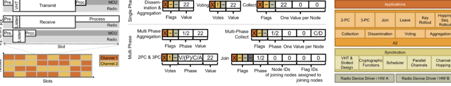
(a) Slotted design of A2. Each slot, a node either transmits, aims to receive (or sleeps). The radio is off during processing to reduce the duty-cycle. X − − 22 Flags Value Dissem-ination & Aggregation X − − 22 0 0
Flags One Value per Node Collect
X ! − V/(P)/C/A 22
Phase
Votes Value
2PC & 3PC Join X − − 1/2 0 0 0 0
Flags Phase Node IDs of joining nodes Flag IDs assigned to joining nodes Voting Multi-Phase Collect Phase X − − 1/2 0 0
Flags One Value per Node
C/D Multi Phase AggregationX − − 1/2 Flags 22 Value Phase S in gl e P ha se M ul ti P ha se X ! − 22 Votes Value −
(b) State and packets per application. Each application utilizes a specific set of flags, votes, and fields.
Radio Device Driver / HW A Radio Device Driver / HW B Synchrotron Applications VHT & Slotted Design Channel Hopping Parallel Channels Cryptographic Functions Scheduler A2
Collection Dissemination Voting Aggregation 2-PC 3-PC Join Leave RolloutKey
Hopping Seq. Rollout
(c) Layered system architecture of A2. The scheduler allows A2to operate multi-ple applications and communication prim-itives.
Figure 5: System architecture and details ofA2. information on nodes interested in joining for a number of slots. In
such scenarios, we see Chaos losing synchronization, as it depends on the constant activity of transmit/receive.
In Synchrotron, we achieve this synchronization by utilizing VHT: a virtual high-definition timer [53]. VHT uses a combination of the stable, low-power low-frequency clock and the (either unsta-ble or energy-hungry) high-frequency clock of a sensor node. This allows Synchrotron to maintain tight synchronization over long periods of network inactivity. In the context of Glossy, VHT is also employed in recent other work [36, 41, 45].
5.2
Frequency Agility
Both Chaos and Glossy see their performance degrade in presence of interference [20, 21, 28, 29, 41, 45]. In Synchrotron, we address this by introducing frequency agility and parallel channels. Channel Hopping for Robustness Nodes in Synchrotron trans-mit in each time slot on a different frequency following a network-wide schedule, similar to WirelessHART, TSCH or Bluetooth. This prohibits interference on individual channels from disturbing the operation of Synchrotron [59] and allows A2to co-exist with other
wireless technologies such as 802.11 or TSCH. Moreover, note that synchronous transmissions in combination with channel hopping have shown their robustness during the EWSN dependability com-petitions, where, for example, all three top ranking teams in 2017 combine these two design elements [20, 41, 45].
Parallel ChannelsThe probability of capture reduces as the num-ber of concurrent transmitters increases [38]. Chaos proposes re-ducing the transmission power while in Synchrotron, we use mul-tiple channels in parallel instead. Each node randomly chooses one channel per time-slot to either receive or transmit. As a result, Syn-chrotron practically reduces network density and thereby increases the probability of capture. Moreover, it does so without increasing the network diameter, as for example, decreasing the transmission power does. As a side effect, this also increases frequency diver-sity and robustness further. In §6.4 we show how the number of channels affects performance.
5.3
Scheduler
Synchrotron offers a scheduler that allows multiple A2
applica-tions to coexist: For example, it can schedule a collect round every 10 seconds, a dissemination round once a minute and schedule
Testbed NodesCoordinator Density Diam.ChannelsTx Power Flags
[#] [ID] [#] [hops] [#] [dBm] [bytes]
Euratech 213 3 106 2 15 0 27
Rennes 180 3 90 2 15 0 23
Indriya 97 35 32 3 2 0 13
Flocklab 29 3 7 4 2 0 4
Table 1: The testbeds we used for evaluation. They vary in density from very dense to low-density deployment, and they are subject to real life interference from users and network deployments.
on-demand services such as join and leave. The scheduler sets pri-orities or deadlines (EDF) to each task. In the packet header of each round, Synchrotron denotes the application type, slot length, the maximum allowed number of slots and start time of the next round.
5.4
Security
Synchrotron provides security and authentication as standardized by 802.15.4. We utilize the hardware security support to ensure that the cryptographic operations complete quickly. In our experience, these mechanisms are essential for Synchrotron: For example, when stress-testing the join service, we would occasionally see nodes with invalid node IDs join. Upon investigation, it turned out that this was due to CRC collisions, i.e., corrupted packets which accidentally had valid CRCs. Enabling message authentication in Synchrotron ensures that these faults do not propagate (c.f., §6.3).
6
EVALUATION
In this section, we evaluate A2on four public testbeds. We begin by discussing the evaluation setup, then we present a single round of each 3PC and join to highlight the inner workings of A2. Next, we evaluate the low-level properties of A2and Synchrotron including
reliability, frequency agility, and long-term performance. Finally, we evaluate the performance of the primitives in A2and compare
it to the state of the art.
6.1
Evaluation Setup
We present our A2implementation and the scenarios, metrics and testbeds used for evaluation.
Implementation 1We implement A2in C for the Contiki OS [16] targeting simple wireless nodes equipped with a low-power radio such as TelosB and Wsn430 platforms which feature a 16bit MSP430 CPU @ 4 MHz, 10 kB of RAM, 48 kB of firmware storage and CC2420 [57] radio compatible with 802.15.4 [30].
Scenarios We evaluate the following applications:
• Disseminate: shares a 4-byte data item to every node; • Max: network aggregation where the nodes collectively
calculate the maximum value of a 4-byte measurement; • Collect: collects a 2-byte data item from every node; • 2PC and 3PC: consensus primitives, as introduced in §3.2
and §3.3;
• Glossy Mode: lightweight dissemination (4-byte value) with-out progress flags, similar to Glossy [23] but run over A2; • LWB: we compare the performance of A2to LWB [21] and LWB-FS [52], which implements forwarder selection as done in CXFS [7].
Depending on the application and testbed, the slot size varies between 3.5 and 7 ms. Unless otherwise mentioned, applications repeat at a 1-minute period. In all experiments, we use a pseudo-random channel-hopping sequence that covers all 16 channels al-lowed in the IEEE 802.15.4 standard. As a result, we run A2with
co-existing 802.11 traffic and other sources such as Bluetooth as our testbeds are deployed in university buildings.
Metrics We focus on the following performance metrics: • End-to-End Loss Rate: to evaluate how reliable a protocol
is. We consider a round reliable only if all nodes receive the final value;
• Radio-on time: is the total time the radio is active during a round, as a proxy for the energy consumed during a round; • Radio Duty Cycle: is the ratio of the time when the radio is
on over the total time, a metric for energy efficiency; • Latency: is the duration of a round until all nodes complete
and they are aware of the final result, i.e., until they enter the final phase.
Testbeds We run our evaluation on four publicly available testbeds deployed in university buildings; namely, Flocklab [40] in ETH, Indriya [11] in NUS, and FIT-IoTLAB [1] in Inria at the sites Rennes and Euratech. The properties of these testbeds are summarized in Table 1, along with the number of parallel channels we use, the transmission power and the length of the A2flags.
6.2
A
2in Action
We illustrate A2by two representative rounds: three-phase commit
and join. We show how the different mechanisms in A2interact when running on large testbeds: Euratech and Rennes.
Three-phase Commit Figure 6 shows a snapshot of a represen-tative 3PC round (c.f., §3.3) in Euratech. All nodes start in phase 0. The coordinator (thick red line) starts the voting phase with a Can commitrequest in slot 1. The request disseminates and nodes merge their votes, until convergence when all progress/vote flags are set. It takes about 70 slots for the coordinator to receive all votes. In this example, all the votes are positive, the coordinator resets all
1The code is available at: https://github.com/iot-chalmers/a2-synchrotron
Voting Phase Pre-Commit Phase Commit Phase
Figure 6: A snapshot of three-phase commit in Euratech. In this example, we show a round of a successful 3PC. The upper figure shows the number of flags each node has set and the lower figure indicates which of the three phases each node is in. The thick red line shows the coordinator, while the other lines belong to the cohort. It takes about 70 slots for the coordinator to receive all votes and to switch to the pre-commit phase. It takes about 30 more slots for the cohort to hear the phase transition. The second and third phases take slightly longer to complete.
flags and triggers a transition to the next phase, Pre-commit. It takes about 30 more slots for the cohort to hear the phase transition. We evaluate three-phase commit performance later in §6.6.
Join We take a close look at the initial joining phase (c.f., §4.2) in the Rennes and Euratech testbeds, with 176 and 212 active nodes respectively. We configure A2to accept 10 new nodes per round. A2 shows a stable performance by joining exactly 10 nodes per round. On Rennes, it – in all our experiments – took a stable 18 rounds to join the 176 nodes, while on Euratech it took 22 rounds. Join executes two additional rounds at the end to make sure no nodes were left behind, so in total it took 20 and 24 rounds, respectively, to join all nodes in the networks. When scheduled back to back, this corresponds to a time of 15 and 23 seconds for 176 and 212 nodes, respectively.
Figure 7 shows a snapshot of a representative round in Eurat-ach. At this point, we have successfully joined 100 nodes, and the coordinator starts a new join round. After only 20 time-slots, all 10 join slots are filled by new nodes. Once this information reaches the coordinator, it triggers the next phase and disseminates the number of new nodes and their indices. It takes 30–40 slots for all nodes to transit, and about 80 to complete. After 120 slots in total, the coordinator sees all the flags set, and knows all 10 nodes have joined successfully. It will then switch to a new join round (not shown).
Collect Phase
Commit and Disseminate Phase
Figure 7: A snapshot of Join in Euratech. In this particular snapshot, we have joined 100 nodes in previous rounds and within this round successfully join 10 further ones. The upper figure shows the number of flags each node has set and the lower figure shows the number of occupied join slots. The thick red line shows the coordinator activity.
Testbed Nodes Rounds Slot Size Slots Total Time
[#] [#] [ms] [#] [s]
Rennes 176 20 7 107 15
Euratech 212 24 7 137 23
Table 2: Summarizing Join performance. Per round, we join up to 10 nodes, limited by the packet size of 802.15.4 and the size of the node IDs, two bytes in this setup. In total, we require 20 and 24 rounds, respectively, and 15 and 23 seconds, respectively to join all nodes.
Type Rx Rx Rx Tx CRC CRCcol . CRCcol .
Tot. Ok Corrupt Tot. Collisions /Rxcor . /Rxt ot .
Multiplier [packets ×106] [packets] [ratio ×10−6]
Rennes 120 103 17 97 84 4.9 0.7
Euratech 135 104 31 101 219 7.0 1.6
Table 3: CRC collisions happen in Rennes and Euratach. Resp. 4.9e-6 and 7.0e-6 of all corrupted packets suffer a CRC colli-sion, i.e., are wrongly classified as correct at the receiver.
6.3
Packet Error Detection
The IEEE 802.15.4 standard provides a 16-bit CRC in the packet footer for transmission error detection. However, in the preliminary evaluation of A2, we noticed CRC collisions: Corrupt bytes in the
packet that accidentally assemble a correct checksum.
Insights The probability to get a 16-bit CRC collision over cor-rupted packets is 2−16≈15×10−6, in a simple uniformly distributed
random scenario. Our runs include hundreds of million packets,
0 2 4 6 8 10 12 14 16
Parallel Channels [#]
0
20
40
60
80
100
120
140
160
Latency [slots]
(a) Rennes
-10.00 dBm -6.44 dBm -4.03 dBm -1.45 dBm 0.00 dBm0 2 4 6 8 10 12 14 16
Parallel Channels [#]
(b) Flocklab
0.00 dBmFigure 8: The effect of parallel channels. (a) On a dense testbed, running on 16 channels decreases latency by a factor of roughly 2.5– 3.5, depending on the transmission power. (b) On a sparse testbed, using many channels decreases the performance due to the decreasing probability of finding neighbours on the same channel. Error bars represent the standard deviation.
including several million corrupted packets, in part because A2 uses dense transmission schedules to enable capture. This results directly in a number of corrupted packets wrongly classified as correct.
SolutionWe use the hardware-based AES integrity check provided by IEEE 802.15.4 radios, not only for its security features but also as an extra guard against packet error. These cryptographic func-tions are hardware-accelerated and hence fast and energy-efficient. Further, on chips such as the CC2420, the integrity check can even be added/checked on the fly when sending/receiving packets. This results in a constant transmission/reception overhead and hence does not affect the relative synchronization among nodes. Evaluation We evaluate the number of CRC collisions in our ex-periments and show how the AES integrity checks (16-bit MIC) improves error detection. The numbers we discuss are with the application Max on Rennes and Euratech, from our long-term ex-periments presented in more details in §6.5. We regard a message as corrupted whenever CRC indicates a failure. Conversely, we detect CRC collisions whenever a packet passes the check but fails the AES integrity check. Table 3 shows the packet statistics for experiments in the Rennes and Euratech testbed.
We have over 100 million received packets in each testbed, out of which 17 and 31 million corrupted packets failing the CRC check. Moreover, we notice 84 and 219 broken packets that fail the AES integrity check but pass the CRC check, which we label as CRC col-lisions. We argue that the additional integrity check is a must since a corrupted packet header could possibly cause arbitrary failures. Further, note that many applications require integrity protection (and sometimes confidentiality), and hence would enable link-layer security regardless.
6.4
Frequency Agility and Parallel Channels
We evaluate A2’s parallel channels feature.
Scenario We run the Max application and vary both the trans-mission power and the number of parallel channels. We cover all
0
20
40
60
80
100
120
140
160
Latency [slots]
11 12 13 14 15 16 17 18 19 20 21 22 23 24 25 26 M A
Channel [#]
0
20
40
60
80
100
PDR [%]
Single channel Multichannel Single channel averageFigure 9: The effect of multichannel on Flocklab.A2channel hopping feature improves reliability while keeping the latency close to the average of the single-channel instances.
testbeds, a number of channels from 1 to 16, and transmission pow-ers 0, -1.4, -4, -6.4 and -10 dBm. We measure the resulting latency, i.e., the number of slots to round completion.
Results Figure 8 shows the detailed results in the Rennes and Flocklab testbeds. In a dense testbed (Rennes), the latency drops by half as we enable two channels in parallel, and the trend continues when adding more channels albeit with a less significant drop. The latency converges around 40–60 slots. Overall, we improve perfor-mance by a factor of up to 3.5 in Rennes. This is key in enabling the realization of the more complex services such as 2PC/3PC/join which would take a prohibitively long time to execute otherwise.
A direct side effect of decreased latency is improved energy-efficiency, as nodes are equally active regardless of the number of channels. Rounds that are 3.5 × faster also consume roughly 3.5 × less energy.
We also run the same experiments in all other testbeds, to select the optimal settings for all subsequent experiments. Table 1 summa-rizes the parameters we select. Depending on the testbed, we select 2 to 15 channels and a transmission power of 0 dBm. Note that the densest testbeds Rennes and Euratech benefit most from more parallel channels. In sparser testbeds, using too many channels reviewdecreases performance, because nodes have a chance to miss one another (senders and receiver select their channel at random). As a result, we select only two channels in Flocklab and Indriya. Channel Hopping We do a limited evaluation of the effect of channel hopping on robustness, as this is already a well-understood topic in the literature [44, 54, 58] and common in today’s low-power wireless protocol stacks, such as Bluetooth and TSCH. Figure 9 shows the results in Flocklab testbed. Using multichannel improves reliability and results in a latency close to the average on all chan-nels.
6.5
Long-Term Performance of
A
2In this section, we benchmark the long-term performance of A2.
We focus on the loss rate to measure the reliability.
Testbed Total [106] Average time [ms]
Points Losses To completion To off Radio-on
Rennes 3.87 0 151 258 137
Euratech 3.72 0 203 328 165
Table 4: Long-term performance ofA2. No single loss over twice 3.7 million messages delivered end-to-end. Average radio-on time for one round: 137–165 ms.
Scenario We run the application Max on Rennes and Euratech for a total of more than 21000 rounds each. In total, this results in 3.7 million points in each network (number of rounds multiplied by number of nodes). In these experiments, we use slots of 3.75 ms to accommodate the processing and communication of 56 bytes packets (header, flags, payload and AES MIC). At the time of the experiments, these testbeds had 181 connected nodes each, and in each experiment we got between 178 to 181 nodes working, and 180 on average.
Results Table 4 summarizes the results. First, note that all the rounds in all runs complete, i.e., all the active nodes participate, contribute and receive the final aggregate. We got zero losses in 3.7 million points over both testbeds. This makes A2suitable for
critical applications with high reliability requirements, such as distributed industrial control systems. Note that in other testbeds and applications, we consistently achieve excellent reliability as discussed in §6.6.
The performance is similar in both testbeds; we focus here on Euratach for the sake of brevity. The average round completion time is 203 ms, i.e., 54 slots. After completion, nodes initiate the final flood. It takes another 34 slots to reach a stage where all nodes turn their radio off, totaling 328 ms. Note that nodes duty cycle their radio within the slots, to accommodate for processing time (c.f., §5.1). As a result, the average radio-on time per round is 165 ms. This is a good indicator for an application to estimate the radio duty cycle required for a Max operation at a given period. A period of 100 seconds would, for example, result in 0.165% duty cycle.
6.6
Cost of Consensus
This section evaluates the performance of network-wide agreement in A2.
Scenario We run five applications with increasing degree of con-sistency; namely, glossy mode i.e., one-to-all with no flags, max and disseminate with all-to-all delivery and flags, two-phase commit and three-phase commit with all-to-all delivery and flags showing the agreement phase and progress, see §6.1 for details on the eval-uated applications. For each experiment, nodes join through the join-primitive of A2then switch to the application; we only focus
on application rounds here. We run this evaluation on four testbeds: Flocklab, Indriya, Rennes and Euratech. We run each application for 1200–1700 rounds, except for Indriya (200 rounds), where collect-ing large amounts of data turned out troublesome due to technical limitations of Indriya.
Results Figure 10 summarizes the loss rate, latency and per-round radio-on time, for each application and testbed. First, we observe a
0.0 100.0 200.0 300.0 400.0 500.0 600.0 Radio on [ms] 0.0 200.0 400.0 600.0 800.0 1000.0 1200.0 Latency [ms]
Glossy Mode Max Disseminate Two-phase
Commit Three-phaseCommit
1e-06 1e-05 0.00010.001 0.01
Loss rate Flocklab #29
Indriya #97 Rennes #180Euratech #213
Figure 10: Cost of Consensus inA2. The cost increases with the number of nodes, and significantly with the level of consensus. 2PC costs twice asMax and Disseminate, while Glossy Mode is cheap since it does not use flags. Error bars represent the standard deviation.
0.0 1e-05 2e-05 4e-05
80 85 90 95 100 Transaction Outcome [%] (a) Vote - 1PC
0.0 1e-05 2e-05 4e-05
Failure rate (b) 2PC Inconsistent Blocked Abort Commit
0.0 1e-05 2e-05 4e-05
(c) 3PC
Figure 11: Consensus outcome of single-phase Vote, 2PC and 3PC in Flocklab under controlled failure. Vote has a low cost but suffers from inconsistencies, 2PC solves inconsistencies with blocking, 3PC trades consistency for liveness and maximizes the ratio of successful (live and consistent) transactions.
cost increase with the number of nodes in the testbed and with the level of consensus. Note, however, that the cost is not proportional to the testbed size. Rennes is, for example, six times larger than Flocklab but only results in about twice the latency. This due to topology differences, in particular, the higher density in Rennes.
We now take a look at the performance of each application. Glossy Modehas the lowest cost due to its simplicity, but also a relatively high loss rate. Max and Disseminate perform roughly the same since they are very similar. Both achieve zero loss end-to-end. Two-phase commitshows roughly twice the cost of Max (latency and radio-on time). This is due to the two phases and to the packet overhead of vote flags. Three-phase commit continues the trend and has slightly more than three times the cost of Max. This is due to the three phases.We achieve a reliability of 100%, 99.9% and 99% for 3PC on Rennes, Flocklab and Indriya, respectively. §6.7 investigates next the transaction outcome for the consensus primitives.
6.7
Consistency of Consensus Primitives
In this section, we evaluate the different consensus primitives in terms of liveness and consistency.
Scenario We compare 2PC and 3PC, and look at the voting phase in isolation. Note that in 2PC, nodes uncertain about the outcome of the transaction resort to blocking to avoid inconsistencies. 3PC, in contrast, never blocks but can result in some inconsistent outcomes, see §3.2 and §3.3.
We run the three primitives on Flocklab for 900 rounds, and inject emulated network failures. At every slot, each node has a given probability (between 0 and 4 · 10−5) to enter a failure state, i.e., be
unable to communicate until the end of the round. A node that is subject to network failure will decide on the protocol outcome autonomously, based on the timeout/recovery policy of 2PC and 3PC. This failure model represents either a severe case of network isolation or a crash where the node is able to recover its state from persistent storage. Note that with per-slot probability, protocols that take more slots to finish a transaction (e.g., have more phases) are more vulnerable to failures – which is fair as a slower protocol does have higher chances to suffer a failure during a round in the real world.
Each transaction starts on a clean slate, with all nodes opera-tional. To separate failures and disagreements, we let all nodes vote for the proposal. As a result, abort is merely due to failures and not due to nodes disagreeing to a proposal. We classify the outcome of each transaction as one of the four categories: (a) commit if all nodes commit in the round; (b) abort if all nodes abort as instructed by the protocol, due to a timeout; (c) blocked if one node (and consequently the network) is blocked for this transaction; (d) inconsistent if there are at least one commit and one abort in the same transaction. Results We summarize the results in Figure 11. First, we notice that all three primitives result in 100% commit rate in case of no injected failures although we run the experiments on Flocklab and use the 16 channels including those polluted by WiFi and Bluetooth, which underlines the reliability of Synchrotron.
Second, we see that Vote suffers from increasing inconsistencies as the failure rate increases. This is because the voting phase does not offer protection against the case that one node votes yes and fails to hear the rest of the votes; thus aborts due to timeout, while the rest of the nodes are not aware of its abort as they all voted yes, heard its yes vote and committed.
Third, we notice that 2PC delivers on the promise of eliminating the inconsistencies, as it orders the nodes that are in the uncertainty state to block (i.e., those who voted yes and failed to hear the outcome). The price to pay is liveness, as the whole protocol has to block until all nodes are available again for recovery.
Finally, 3PC results in few inconsistencies in favor of liveness. Note that it has a significantly higher rate of successful transac-tions (live and consistent) than Vote or 2PC. We conclude that for applications that cannot afford inconsistencies, then 2PC is a safe solution. For applications that cannot afford to block but can do with little inconsistencies then 3PC is a practical option.
0.0
0.1
0.2
0.3
0.4
0.5
0.6
Duty cycle
[%]
0.0
200.0
400.0
600.0
800.0
Latency [ms]
Max Disseminate 2PC
3PC
Collect
Collect LWB-FS
LWB
0.0001
0.001
0.01
0.1
Loss rate
A
2LWB
Figure 12: Performance comparison between A2 and LWB(-FS) in Flocklab. Period: 1 minute, payload: 2 bytes.A2 outperforms the state of the art in terms of latency and reliability. LWB-FS achieves the lowest duty cycles but is also the least reliable solution.
6.8
Comparison to the State of the Art
We evaluate the performance of the different applications imple-mented over A2and compare them to the state of the art: the
Low-power Wireless Bus (LWB) and LWB with forwarder selection (FS). For a description of the applications see §6.1.
ScenarioWe limit this evaluation to Flocklab, as the other testbeds are not supported in the LWB code base. The comparison between A2, LWB and LWB-FS is on Collect, but we also show A2’s other
primitives for reference. We scale the duty-cycle calculation to re-flect a rate of one packet per minute per node to emulate an IoT data collection scenario, e.g., building monitoring or climate control, and we use a payload of two bytes. As the network consists of 29 nodes, the collect payload in A2is 58 bytes (the packet needs enough space
for a value from each node). Note that the implementations of LWB and LWB-FS do not support multi-channel operation and our ex-periments are limited to channel 26. Thus, these two protocols do not employ frequency agility as A2does.
Results We summarize the results in Figure 12. For A2, we notice that Collect has a latency and duty cycle slightly over Disseminate and Max, because Collect has a larger payload.
LWB Collect has a higher duty cycle of 0.45% vs. 0.29% in A2, a
higher latency of 730 vs. 222 ms, and a significant loss-rate of 2.82%. The higher loss-rate can be explained by two factors: (a) LWB uses a single channel, which makes it vulnerable to interference; and (b) LWB nodes do not wait for flags from the sink. Instead, they use a fixed number of transmissions, which has the benefit to yield a fixed latency. We note that the higher latency with the default settings of LWB could be significantly lowered: By taking a 6 ms data slot for each of the 29 nodes and a 10 ms contention slot, the
latency can be as low as 190 ms per one LWB round, and thereby be comparable to A2in terms of latency. The loss rate, however,
would be unaffected.
With its forwarder selection feature, LWB-FS is able to dynami-cally turn off the nodes off the path between source and sink. This makes LWB-FS the most energy-efficient solution, but also the least reliable one, as there are fewer nodes participating in the flood. Overall, A2is by far the most reliable, it has the lowest latency but a worse duty cycle than LWB-FS.
We discuss the potential cost of a hypothetical 2PC solution on top of LWB: Such a solution would require at least two Collect rounds, as each phase involves getting a vote/ack from the cohort. This would lead to a latency above 1400 ms, that is, slower than A2 (with default settings) by a factor 6.
7
RELATED WORK
In this section, we discuss the broader field of synchronous transmis-sions and advanced communication primitives in wireless sensor networks (WSNs).
Synchronous Transmissions Glossy [23] pioneered the field of synchronous (or concurrent) transmissions in WSNs. In Glossy, nodes synchronously transmit the same data packet. Tight synchro-nization ensures non-destructive interference of the transmissions and allows receivers to recover the packet.
Glossy provides network-wide flooding, i.e., from a single sender to all nodes in the network, on millisecond scale. Others, such as LWB [21], Splash [12], Choco [56] base on Glossy to schedule individual network-floods to provide data collection. Virtus builds on Glossy to provide virtual synchrony [4] and Crystal [31] relies on data prediction to reduce the number of Glossy floods. CXFS [7], Sparkle [63] and others [6, 33, 52, 62, 64] limit the number of concurrent transmitters in Glossy or LWB to improve energy efficiency.
In contrast to Chaos and A2, nodes in Glossy always need to transmit the same data packet to enable constructive interference. As a result, they cannot exploit spatial diversity as Chaos and A2
do. Moreover, their tight timing requirements of constructive inter-ference limit the options of in-network processing of data. Over-all, synchronous transmissions enable low-latency network-wide communication. A2builds on these results and provide advanced
communication primitives.
Conventional Networking Protocols Conventional asynchro-nous protocols such as ContikiMAC [15] or even newer TDMA approaches such as TSCH [17, 30] and Orchestra [18] when com-bined with routing protocols such as RPL [60], CTP [25] pro-vide best-effort low-power routing. WSN rate-controlled proto-cols [14, 32, 35, 49, 51] or TCP for 6LoWPAN [19] enable end-to-end reliability on top of a best-effort routing protocol. These protocols have significant higher latencies than A2and other approaches based on synchronous transmissions [21, 38].
Further, supporting group communication on top of a routing protocol is a challenge per se. Solutions such as BMRF [24] or SMRF [48] provide such feature in a RPL multicast context, but they exhibit high latencies and loss rates of a few percent or tens of percent. Most importantly, existing group communication proto-cols are best-effort, i.e., they do not provide end-to-end reliability.