ACTA UNIVERSITATIS
UPSALIENSIS
Digital Comprehensive Summaries of Uppsala Dissertations
from the Faculty of Science and Technology
1449
Workpiece steels protecting
cutting tools from wear
A study of the effects of alloying elements on
material transfer and coating damage mechanisms
TOSHIHARU AISO
ISSN 1651-6214 ISBN 978-91-554-9743-9
Dissertation presented at Uppsala University to be publicly examined in Häggsalen, Ångströmlaboratoriet, Lägerhyddsvägen 1, Uppsala, Friday, 16 December 2016 at 13:15 for the degree of Doctor of Philosophy. The examination will be conducted in English. Faculty examiner: Dr Staffan Söderberg.
Abstract
Aiso, T. 2016. Workpiece steels protecting cutting tools from wear. A study of the effects of alloying elements on material transfer and coating damage mechanisms. Digital
Comprehensive Summaries of Uppsala Dissertations from the Faculty of Science and Technology 1449. 76 pp. Uppsala: Acta Universitatis Upsaliensis. ISBN 978-91-554-9743-9.
The vision of this thesis is to improve the machinability of workpiece steels. Workpiece material frequently transfers to the cutting tools during machining, and the transfer layers then forming on the tools may give both good and bad effects on machining performance and tool life. The objective of this work is to understand the effects of alloying element additions to workpiece steels on material transfer and the roles of the formed transfer layers on friction characteristics and wear of tools.
To isolate and study the influence of the individual alloying elements, model steels are specifically designed. These steels include one reference with C as the only alloying element and others alloyed also with single additions or combined additions of 1 mass% Si, Mn, Cr and Al. The experiments are performed using both a sliding test, simulating the material transfer in milling, and a turning test.
In a sliding contact, the mode of transfer is strongly dependent on the normal load and sliding speed. Material transfer initiates extremely fast, in less than 0.025 s, and characteristic transfer layers develop during the first few seconds. The different steel compositions result in the formation of different types of oxides in the transfer layers. At the workpiece/tool interface where the conditions involve high temperature, high pressure and low oxygen supply, easily oxidized alloying elements in the steel are preferentially transferred, enriched and form a stable oxide on the tool surface. The degree of enrichment of the alloying elements in the oxides is strongly related to their tendencies to become oxidized.
The difference in melting temperature of the oxides, and thus the tendency to soften during sliding, explains the difference in the resulting friction coefficient. The widest differences in friction coefficients are found between the Si and Al additions. A Si containing oxide shows the lowest friction and an Al containing oxide the highest.
The damage mechanism of coated tools is chiefly influenced by the form and shear strength of the transferred material. Absence of transfer layer or non-continuous transferred material leads to continuous wear of the coating. Contrastingly, continuous transfer layers protect it from wear. However, transfer layers with very high shear strength result in high friction heat and a large amount of steel transfer. This leads to rapid coating cracking or adhesive wear.
Keywords: Metal cutting, Steel, Cutting tools, Transfer, Coating, Sliding
Toshiharu Aiso, Department of Engineering Sciences, Applied Materials Sciences, Box 534, Uppsala University, SE-75121 Uppsala, Sweden.
© Toshiharu Aiso 2016 ISSN 1651-6214 ISBN 978-91-554-9743-9
List of Papers
This thesis is based on the following papers, which are referred to in the text by their Roman numerals.
I Influence of contact parameters on material transfer from steel to TiN coated tool – optimisation of a sliding test for simulation of material transfer in milling
T. Aiso, U. Wiklund
Tribology - Materials, Surfaces & Interfaces (2016),
http://dx.doi.org/10.1080/17515831.2016.1202548
II Effect of Si and Cr additions to carbon steel on material transfer in a steel/TiN coated tool sliding contact
T. Aiso, U. Wiklund, M. Kubota, S. Jacobson
Tribology International 97 (2016) 337–348.
III Influence of Mn and Al additions to carbon steel on materi-al transfer and coating damage mechanism in a sliding con-tact between steel and TiN coated HSS tool
T. Aiso, U. Wiklund, M. Kubota, S. Jacobson
Tribology International 101 (2016) 414–424.
IV Effect of combined additions of Si, Mn, Cr and Al to carbon steel on material transfer in a steel/TiN coated tool sliding contact
T. Aiso, U. Wiklund, M. Kubota, S. Jacobson
Submitted for publication in the NORDTRIB 2016 special issue of Wear
V Effect of Si and Al additions to carbon steel on material transfer and coating damage mechanism in turning with CVD coated tools
T. Aiso, U. Wiklund, M. Kubota, S. Jacobson
Wear 368–369 (2016) 379–389.
Reprints were made with permission from the respective publishers. Regard-ing Paper I, the followRegard-ing acknowledgement is added; copyright © The
Insti-tute of Materials, Minerals and Mining, reprinted by permission of Taylor & Francis Ltd, www.tandfonline.com on behalf of The Institute of Materials, Minerals and Mining. This is the authors accepted manuscript of an article published as the version of record in Tribology - Materials, Surfaces & Inter-faces 22 Jul 2016.
Other papers
Magnetization analysis of Ba ferrite magnets by electron holography
T. Aiso, D. Shindo, T. Sato
Journal of Magnetism and Magnetic Materials 318 (2007) 18–22.
In situ Lorentz microscopy and electron holography of magnetization process in ferrite magnets
T. Aiso, D. Shindo, T. Sato
Author’s contribution to the papers
I Major part of planning, experimental work, evaluation and writing. II Major part of planning, experimental work, evaluation and writing. III Major part of planning, experimental work, evaluation and writing. IV Major part of planning, experimental work, evaluation and writing. V Major part of planning, part of experimental work, major part of
Contents
1. Introduction ... 11
1.1 Metal cutting ... 12
1.1.1 Chip forming process ... 12
1.1.2 Cutting operation ... 13
1.1.3 Cutting tools ... 13
1.1.4 Tool wear ... 14
1.2 Steel characteristics that affect machinability ... 15
1.3 Material transfer ... 16
1.4 Research objective ... 18
1.5 Research approach and organization of papers ... 18
2. Material and methods ... 20
2.1 Workpiece materials ... 20
2.1.1 Case hardening steel ... 20
2.1.2 Model steel ... 21
2.2 Tool materials ... 23
2.2.1 PVD coated high speed steel ... 24
2.2.2 CVD coated cemented carbide ... 24
2.3 Crossed cylinders sliding test ... 24
2.3.1 Test setup ... 25
2.3.2 Contact parameters ... 26
2.4 Turning test ... 28
2.5 Analytical techniques ... 29
2.5.1 Scanning electron microscopy (SEM) ... 29
2.5.2 Transmission electron microscopy (TEM) ... 29
2.5.3 Energy dispersive X-ray spectroscopy (EDS) ... 29
2.5.4 Focused ion beam (FIB) ... 30
2.5.5 X-ray photoelectron spectroscopy (XPS) ... 30
2.5.6 Auger electron spectroscopy (AES) ... 30
2.5.7 White light interference profilometry ... 30
2.5.8 Nanoindentation ... 30
3. Effect of contact parameters on material transfer in a sliding contact (Paper I) ... 32
3.1 Influence on material transfer from normal load and sliding speed ... 32
4. Effect of single additions of Si, Mn, Cr and Al on material transfer in a
sliding contact (Paper II, III) ... 35
4.1 Friction characteristics ... 35
4.2 Surface appearance of tool cylinders and transfer layer composition 36 4.3 Transfer and damage of the coating slid against the Base steel ... 39
4.4 Transfer and damage of the coating slid against the Si alloyed steel . 40 4.5 Transfer and damage of the coating slid against the Cr alloyed steel 42 4.6 Transfer and damage of the coating slid against the Al alloyed steel 43 4.7 Transfer and damage of the coating slid against the Mn alloyed steel ... 46
4.8 Friction and coating damage mechanisms ... 47
4.9 Mechanism of oxide layer formation ... 49
4.10 Summary ... 50
5. Effect of combined additions of Si, Mn, Cr and Al on material transfer in a sliding contact (Paper IV) ... 51
5.1 Friction, transfer and damage of the coating slid against the SiMn, SiCr and SiMnCr alloyed steels ... 51
5.2 Friction, transfer and damage of the coating slid against the SiMnAl and SiMnCrAl alloyed steels ... 53
5.3 Summary ... 55
6. Effect of single additions of Si and Al on material transfer in turning (Paper V) ... 56
6.1 Transfer and wear of the cutting tools in the region of depth of cut .. 56
6.2 Transfer and crater wear of the cutting tools ... 60
6.3 Similarities between turning, sliding tests and milling ... 61
6.4 Summary ... 62
7. Conclusions ... 63
8. Outlook ... 66
9. Sammanfattning på svenska (Summary in Swedish) ... 67
Acknowledgments... 71
Appendix ... 72
Abbreviations
AES Auger electron spectroscopy
CVD Chemical vapour deposition
EDS Energy dispersive X-ray spectroscopy
FIB Focused ion beam
HAADF High-angle annular dark field
HSS High speed steel
PVD Physical vapour deposition
SEM Scanning electron microscopy
STEM Scanning transmission electron microscopy
TEM Transmission electron microscopy
1. Introduction
Bars and wire rods of steels are widely used in structural components of the engine, drivetrain, suspension systems and other parts of automobiles. These steels undergo a variety of manufacturing processes, including e.g. forging, machining and heat treatment, when manufactured into the components. Machining, such as turning, drilling and hobbing, is one of the most im-portant processing types to accomplish desired shapes with high precision. However, the cost of machining is typically significantly higher than that of the material to process or that of the other processes [1]. An improvement of the productivity of machining is thus the most efficient way to decrease the cost of the manufactured components.
The term machinability refers to the influence of the workpiece on the productivity of machining. However, machinability does not mean a unique property of the workpiece material. Rather, there are several criteria for ma-chinability, such as tool life, chip breakability, surface integrity and cutting force. Tool life is considered as the most important in many cases when ma-chining steels for machine construction, since it is closely related to the pro-duction costs. Tool life is evaluated by the amount of material removal until the tool becomes too inefficient due to wear or other damage.
In order to decrease the size and weight of the structural components to improve the fuel efficiency of automobiles, it is desired to use high strength steels. High strength steels with high hardness usually deteriorate the ma-chinability. Free-cutting additives, generally S and Pb, are thus added to the steels to obtain good machinability. However, the use of high amounts of S is difficult, as the S addition often results in deterioration of mechanical properties like toughness and fatigue strength. Pb is regarded to be an envi-ronmentally harmful substance and its use is restricted to some extent, alt-hough it strongly enhances the machinability of steels without seriously de-teriorating the mechanical properties. Furthermore, dry or semi-dry machin-ing, instead of the use of any cutting fluid, is desired to reduce industrial wastes. This often leads to reduced machining productivity. With these backgrounds, new knowledge and new techniques to improve machinability are strongly needed.
1.1 Metal cutting
1.1.1 Chip forming process
To understand the tool wear mechanisms, it is of great importance to know the severe conditions around the cutting edge during machining. Technical terms and cutting parameters in chip forming process are defined in Fig. 1. In this process, the workpiece is shaped by removing material, using a cut-ting tool. The workpiece around the cutcut-ting edge is plastically deformed, primarily in three distinct zones. The chip is formed in the primary shear zone. In the secondary shear zone, the chip undergoes a further plastic de-formation in the contact with the rake face of the tool. The workpiece is also deformed in the contact zone with the flank face of the tool, called the ter-tiary shear zone. The shear strain in the primary shear zone reaches 2–4, while in the secondary shear zone it exceeds 20 [3]. The strain rate in the secondary shear zone is at least 104 s-1 [3]. These large, high-speed
defor-mations result in high temperatures in the shear zones, as almost all energy spent in the deformation is transformed into heat. The chip body reaches temperatures in the range 200–350 ºC [3], and at the chip/tool interface the maximum temperature may exceed 1000 ºC [4].
The maximum stress acting on the tool is associated to the yield stress of the workpiece material. The maximum normal stress has been reported to be about 500–1600 MPa [3]. Due to such high normal stresses, the real contact area between the chip and the tool becomes a large proportion of the appar-ent contact area. In this situation, the major part of chip/tool contact on the rake face is under the seizure and the relative motion is carried out by shear-ing of the weaker of the two materials. The normal stress has a maximum at the cutting edge and decreases along the rake face. Sliding ensues around the end of contact zone, where the normal stress becomes lower.
1.1.2 Cutting operation
Many types of cutting operations, such as turning, milling, drilling, tapping and broaching, are employed in the production of structural components. The operation types can be divided into continuous and intermittent cutting procedures. In continuous cutting, e.g. turning and drilling, the cutting tool continuously contacts the workpiece material during machining. The heating in the contact between the chip and the tool is intense, since there is no op-portunity to cool. The major part of the rake face has virtually no supply of oxygen from the environment [3]. In contrast, in intermittent cutting, e.g. milling, the tool repeatedly undergoes short term contacts with the work material followed by a period out of contact. The cutting edges are stressed and heated during the contact, and they are unstressed and allowed to cool during the period out of contact. This repeated process causes both mechani-cal and thermal fatigue of the tools [3]. The period out of contact also allows oxygen from the environment to access to the rake face. These differences in the contact situations between continuous and intermittent cutting affect the tool damage mechanisms and the interaction between the chip and the tool.
1.1.3 Cutting tools
Today, tools coated with physical vapour deposition (PVD) or chemical vapour deposition (CVD), which significantly improve the wear and thermal resistances, have become standard in machining of steels. The majority of the tools used in industrial machining of steels for machine construction are made of either PVD coated high speed steel (HSS) or CVD coated cemented carbide.
HSS is used mainly because it enables manufacturing of tools with com-plicated geometries such as a hob or broach. HSS shows a high toughness and is therefore suitable for intermittent cutting involving mechanical shock, such as in hobbing. HSS contains relatively large amounts of the carbide forming elements of Cr, W, Mo and V. The large fraction of these carbides present in the martensite matrix enhances the wear resistance and hot hard-ness. The hot hardness can be further increased by adding Co to the HSS. However, HSS may thermally soften during machining if heated to above about 600°C [3, 5]. Thus, the use of HSS is generally limited to relatively low-speed machining. Better performance is achieved using powder metal-lurgical HSS with uniform and fine carbide distribution. These tool materials often have PVD coatings such as TiN, TiAlN and CrAlN. PVD coating can be deposited to HSS substrates, avoiding the high temperatures in CVD pro-cesses, which would cause thermal softening of HSS. PVD coatings offer superior hardness and low chemical reactivity. These ceramic coatings are inherently brittle, but the compressive stress in the PVD coating gives high crack resistance.
Cemented carbide is another common tool material, showing much better hot hardness and wear resistance than HSS. It is extensively used mainly for high speed machining operation, such as turning. Cemented carbide is a composite material consisting of fine grains of carbides, commonly WC, bonded by a binder metal, commonly Co. Typically, WC particles with a grain size of about 0.5–10 μm are sintered with about 4–12 mass% of Co binder [3]. Decrease in either the WC grain size or the Co amount results in higher hardness. TiC and TaC particles are often added to increase the wear resistance. In many cases, cemented carbide is coated using CVD, which offers relatively uniform and thick coating. The most common coatings have TiCN, which has high wear resistance, as an inner layer, and Al2O3, which is
chemically resistant and heat insulating, as an outer layer. TiN is used as a top layer to color the surface to easily detect wear.
1.1.4 Tool wear
Cutting tool wear occurs under severe conditions involving high temperature and high pressure in the contact with the freshly formed surface of the work-piece material. Abrasive, adhesive, diffusion and oxidation wear are all known to be important mechanisms and they act simultaneously with major influence from one or more [4]. Abrasive wear of the tool surface is due to the grooving action of hard particles or inclusions in the work material. Ad-hesive wear is caused by the micro-welding at the chip/tool interface. Small pieces of the tool material are transported away with the chip when these welded parts are sheared off. Diffusion wear is due to atomic transport of tool element into the chip. Oxidation wear is caused by the chemical reaction occurring between the tool material, the workpiece and surrounding atmos-phere or cutting fluid. This wear is due to the removal of reaction products by the chip flow. At relatively low cutting speed, i.e. at low temperature, abrasive and adhesive wear are dominant. As the cutting speed is increased, diffusion and oxidation mechanisms become more important.
Common wear types of cutting tools include flank wear, crater wear and notch wear, see Fig. 2. Flank wear arises at the front edge of the flank face, mainly due to abrasive wear. Crater wear appears at the position of maxi-mum temperature on the rake face and is mainly caused by a combination of abrasive and diffusion wear. Notch wear occurs at the region where the out-side edge of the chip passes over the tool surface. The wear in this region is mainly abrasive and adhesive wear. This region allows access of oxygen from the surrounding atmosphere, and thus the wear mechanisms are largely affected by chemical reaction with the atmosphere.
Figure 2. General types of cutting tool wear [2].
Coating can increase the resistance against some or all wear mechanism described above. However, coatings give almost no effect when the tool failure occurs through plastic deformation and fracture of the substrate mate-rial. Thus, failure of a coated HSS tool can be caused by detachment of the coating due to premature deformation of the HSS substrate, rather than due to gradual wear of the coating [6]. This is because the HSS substrate softens when the temperature at the interface exceeds about 600 °C [3, 5]. The sof-tening of the substrate results in loss of support for the surface coating and it makes the coating deform, crack and fracture [7–9]. This process is aggra-vated with increasing the sliding speed due to the intensified friction heating [8, 9]. In such situation, thermally induced phase transformation to soft aus-tenite is often observed as the white etching layer underneath the coating. Trent and Wright [3] claimed the white etching layer is a result of the trans-formed region of the HSS substrate having been above 1173 K.
1.2 Steel characteristics that affect machinability
The machinability of steels generally decreases with increasing hardness. However, the high ductility associated to steels with low hardness also dete-riorates the machinability. Actually, it has been reported that the machinabil-ity is best within a certain range of carbon content [10]. Carbon steels as-rolled or normalized before machining usually have a ferrite-pearlite micro-structure. Alloy steels, added with e.g. Cr, Ni and Mo, often also contain bainite and martensite when as-rolled or normalized. This results in higher hardness and poor machinability. In many cases, the alloy steels are heat-treated with controlled cooling to have a ferrite-pearlite microstructure.
When comparing between steels of approximately the same hardness, a ferrite-pearlite steel has better machinability than a tempered martensite steel [11]. This is explained by the fact that in the ferrite-pearlite structure soft ferrite is mainly responsible for the deformation in the shear zone, which
reduces the cutting force [11]. This effect is further promoted with a coarse ferrite-pearlite microstructure [12].
Additions of S, Pb and Ca are extensively used to improve the machina-bility. S addition improves the machinability due to the formation of sulfide inclusions, mainly MnS. When deformed, cracks generated by stress concen-trations caused by difference in mechanical properties between the sulfide and steel matrix reduce the energy required for the shearing of the workpiece [13, 14]. The friction situation at the chip/tool interface may also be im-proved by the attachment of softened sulfide on the tool [15]. Pb is present as inclusions of metallic lead, as the solubility of it in the steels is almost zero. Pb melts during machining because of its low melting point about 327 ºC, and molten Pb improves the friction situation at the chip/tool interface [16–18]. Molten Pb also causes embrittlement of steels in the shear zone, resulting in good chip breakability [19]. However, S and Pb are difficult to use in higher amounts, because of their detrimental effects on mechanical properties and environmental impact. Ca addition can decrease the melting point of oxide inclusions inevitably contained in the steels. These oxide in-clusions can soften due to the cutting heat, attach to the tool face and protect it from wear [20–22]. This mechanism however requires high temperature to soften the oxides, and thus the effect appears only in relatively high speed machining.
A number of studies on other techniques for improving machinability, e.g. Bi addition, sulfide morphology modification and BN addition, have been performed. Bi has a low melting point, about 271 ºC, and gives similar ef-fects as Pb [23, 24]. The sulfide morphology modification is made with e.g. additions of Ca, Mg and Zr [25, 26]. The additions of them make the distri-bution of sulfides more uniform and their shapes more globular, which sup-presses the decrease in work material toughness. Hexagonal boron nitride is known as a solid lubricant because of its layered crystal structure with easi-ness of cleavage fracture. The BN added steels are reported to have im-proved machinability [27].
1.3 Material transfer
Material transfer from the workpiece to the tool frequently occurs in machin-ing and it influences the contact conditions and tool life. The transfer layers formed on the tools may have both good and bad effects on machining per-formance and tool life. When machining steels with a multi-phase micro-structure, under certain conditions built-up edges can be generated by adhe-sion and accumulation of workpiece material on the cutting edges [3]. The built-up edges are usually undesired since they deteriorate the dimensional
reported that a stable built-up edge with high hardness of more than 700 HV was formed when machining Ti added steels [28]. This prolonged the tool life in drilling with a HSS tool. In recent years, Kümmel et al. [29] demon-strated through a detailed analysis of the built-up edges that the degree of coverage by built-up edges influenced the wear of the cutting edge. They have also attempted to stabilize built-up edges by texturing the tool surface, in order to use them as protective layers [30]. Atlati et al. [31] studied the relationship between the formation of the built-up edges and friction condi-tions on the tools to predict the formation of the built-up edges.
In dry hobbing of case hardening steels, it has been reported that the transfer layers formed on the rake face of the tool prevented crater wear [32]. Gerth et al. [2, 33] studied the details of such transfer layers formed in hob-bing, as shown in Fig. 3. They reported on transfer layers on the rake face, consisting of oxides of Fe, Cr, Mn and Si. All these elements except oxygen were constituents of the steel work material. They suggested that this oxi-dized transfer layer reduced both the wear of the tool and the friction be-tween the chip and the tool. These effects are very attractive for industry, since this type of oxidized transfer layer can likely be formed and improve tool life without special techniques, such as free-cutting additives and tool texturing.
Gerth et al. [2, 34] reported that such an oxidized transfer layer was not formed on the rake face in turning. Based on these results [2, 33, 34], the steel composition and the operation type largely influence the compositions and properties of transfer layers, and thus friction and wear. A deepened understanding of material transfer mechanisms would make it possible to take advantage of transfer layers with further positive effects.
Figure 3. Cross-section of the transfer layer on the rake face of a coated HSS hob
1.4 Research objective
The objective of this thesis is to understand the effects of alloying element additions to workpiece steels on material transfer and the roles of transfer layers on friction characteristics and wear of tools. The present work is in-tended to provide knowledge on how to optimize the steel composition to promote the formation of beneficial transfer layers and good machinability. This thesis mainly investigates oxidized transfer layers as shown in Fig. 3, focusing on the importance of oxygen supply to the chip/tool contact.
1.5 Research approach and organization of papers
To isolate and study the influence of the individual alloying elements, model steels designed specifically for this purpose are necessary. The model steels in this work include one reference with C as the only alloying element (Base steel) and other steels alloyed also with either a single or combinations of elements from the group Si, Mn, Cr and Al, each element consistently added to 1 mass%. These commonly used alloying elements were chosen because they are easily oxidized and thus expected to strongly influence the material transfer. All steels are given a similar microstructure and hardness using heat treatment control. This means that the only significant difference is their chemical compositions.
A crossed cylinders sliding test, simulating the contact between the chip and the cutting tool, is used in this work. This test is suitable for reproducing the transfer layers formed in milling [35] and it allows well controlled stud-ies. Turning tests are also performed, since the type of cutting operation af-fects material transfer and tool damage mechanisms.
The thesis comprises five papers, see Table. 1. First, the influence of the sliding test parameters was studied using a commercial steel (Paper I). Sec-ond, the effect of single additions of Si, Mn, Cr and Al was investigated (Paper II, III). Next, the effect of combined additions of these elements was systematically studied to obtain knowledge more relevant to commercial steels (Paper IV). Finally, the turning tests were conducted using a few se-lected model steels to understand the effect of operation type (Paper V).
Table 1. Overview of the main topics in each paper.
Paper Tests Steels Objective
I Sliding test
(relevant for milling) Commercial steel
Effect of contact parameters on material transfer
II Sliding test (relevant for milling)
Model steels with
single additions Effect of Si and Cr additions on material transfer III Sliding test
(relevant for milling)
Model steels with
single additions Effect of Mn and Al additions on material transfer IV Sliding test
(relevant for milling)
Model steels with
combined additions Effect of combined additions of Si, Mn, Cr and Al on material transfer V Turning test Model steels with single additions Effect of the operation type on mate-rial transfer
2. Material and methods
2.1 Workpiece materials
A commercial case hardening steel and ten specifically designed model steels were prepared as workpiece materials in the present research. The case hardening steel was used to investigate the effect of sliding contact parame-ters in a crossed cylinders sliding test (Paper I). This steel is identical to that used in a previous study [35] which employed the same sliding test. The ten model steels were used in order to isolate and study the influence of individ-ual or specific combination of alloying elements (Paper II–V).
2.1.1 Case hardening steel
Case hardening steels are widely used for structural components such as gears, shafts and bearings. Components made of these steels are first shaped, and then their surfaces are hardened to increase the wear resistance and the fatigue strength. The steels have low carbon content mainly to maintain suf-ficient toughness in core region after hardening. They commonly contain alloying elements such as Mn, Cr, Mo and Ni to have sufficient hardenabil-ity. The present work focuses on soft part machining, i.e. prior to hardening. The case hardening steel EN-ISO 20NiCrMo2 was employed as the workpiece material in this work, see Table 2 for the chemical composition. The blanks were cast, hot rolled, forged into shape and subsequently heat-treated with controlled cooling by the manufacturer. The controlled cooling was carried out to avoid the formation of bainite and martensite, as these microstructures cause higher hardness and poor machinability. Consequently, the steel had a ferrite-pearlite microstructure and a hardness of around 180 HV. For the sliding test, work cylinders of four different diameters were cut out; 139, 110, 80 and 54 mm, all controlled to within 0.6 mm of those values. The work cylinders were turned right before starting the test to ensure a clean surface was achieved. This turning was performed using coated car-bide tools under dry condition, with a cutting speed of 265 m/min, a feed of 0.061 mm/rev and a cutting depth of 0.1 mm.
Table 2. Chemical composition (mass%) of 20NiCrMo2.
C Si Mn S Cr Mo Ni Al Cu Sn Others
0.20 0.24 0.86 0.013 0.55 0.18 0.58 0.039 0.21 0.012 0.03
2.1.2 Model steel
To achieve very controlled experiments, model steels nominally containing 0.55 mass% of C were prepared as workpiece materials, see Table 3 for the compositions. In the Base steel, C was the only alloying element. The Si, Mn, Cr and Al alloyed steels also contained nominally 1 mass% of Si, Mn, Cr or Al, respectively. Five other steels included 0.55 mass% C, 1 mass% Si and one or more of 1 mass% Mn, 1 mass% Cr and 1 mass% Al. Here, the steel added with C, Si and Mn is called the SiMn alloyed steel, and the same prin-ciple applies for the other steels.
The steels were melted in a vacuum melting furnace, cast into 180 kg in-gots, and forged into round bars with a diameter of 70 mm. The round steel bars were heated at 1523 K for 120 min and air-cooled to room temperature for homogenization to reduce the segregation of the alloying elements. Then they were austenitized at 1203 K for 30 min and air-cooled to room tempera-ture for normalizing. Subsequently, each steel underwent different heat treatments, as shown in Table 4, to minimize differences in microstructure and hardness. The austenitizing and annealing temperatures were varied to decrease the difference in the austenite grain size and the hardness, respec-tively. The steels were austenitized at 1123 or 1223 K for 30 min, and oil-quenched or air-cooled to room temperature, and subsequently annealed at 763–1023 K for 300 min. The oil quench was used for accelerated cooling to prevent the formation of coarse ferrite grains and to obtain sufficient hard-ness for the Base steel and the Al alloyed steel. The heat treatment cycles in Table 4 were designed based on preliminary tests performed with broadly varied heat-treatment temperature, see Appendix for details.
Cylinders for the sliding and turning tests, 57 mm in diameter, were cut out from the heat-treated round steel bars. Before starting the sliding test, the cylinders were turned as in the case of the case hardening steel, here with a cutting speed of 250 m/min. This resulted in similar surface roughness of about Ra 0.5–0.8 μm for all steels.
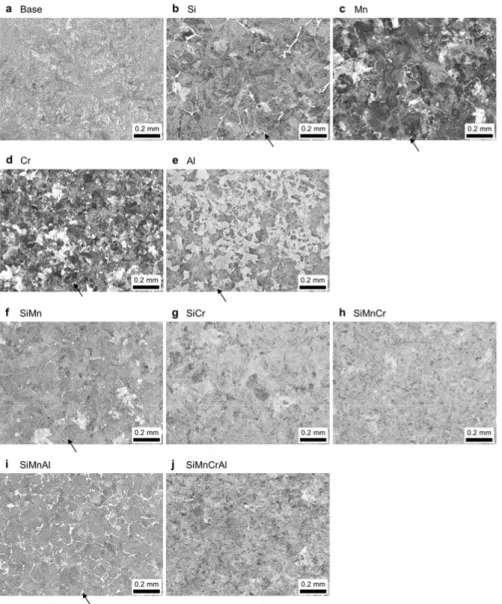
The microstructure and the Vickers hardness of the steels are shown in Fig. 4 and Table 3, respectively. All steels mainly consisted of a fine pearlite microstructure, although the Base steel possibly included some amount of tempered martensite, and some of other steels contained small amounts of ferrite. The hardness of all steels was around 200 HV, with only the SiMnCrAl alloyed steel being slightly harder.
Please note that Fig. 4 and Table 3 show representative data obtained from the steels used for the sliding test (Paper II–IV). For the turning test
(Paper V), the steels were not derived from the same charges, but only small variations in composition, microstructure and hardness were found (see Pa-per V for details).
Table 3. Chemical composition (mass%) and hardness (HV) of the model steels.
C Si Mn Cr Al S Hardness Base 0.57 0.005 0.001 0.001 0.005 0.001 202 Si 0.56 1.001 <0.001 <0.001 0.007 0.001 199 Mn 0.56 0.003 1.001 0.002 0.003 0.001 206 Cr 0.56 0.002 <0.001 1.007 0.003 0.001 194 Al 0.56 0.003 0.001 0.001 0.992 0.001 192 SiMn 0.55 1.006 1.000 <0.001 0.003 <0.001 197 SiCr 0.56 1.002 <0.001 1.006 <0.001 <0.001 202 SiMnCr 0.55 1.004 0.997 1.006 0.002 <0.001 212 SiMnAl 0.57 0.981 1.006 <0.001 1.013 <0.001 208 SiMnCrAl 0.56 0.984 1.006 0.994 0.948 <0.001 225
Table 4. Heat treatment cycles of the model steels.
Base 1123 K/30 min – Oil quench → 763 K/300 min Si 1223 K/30 min – Air cooling → 873 K/300 min Mn 1123 K/30 min – Air cooling → 773 K/300 min Cr 1123 K/30 min – Air cooling → 903 K/300 min Al 1223 K/30 min – Oil quench → 843 K/300 min SiMn 1223 K/30 min – Air cooling → 973 K/300 min SiCr 1223 K/30 min – Air cooling → 1023 K/300 min SiMnCr 1223 K/30 min – Air cooling → 1003 K/300 min SiMnAl 1223 K/30 min – Air cooling → 993 K/300 min SiMnCrAl 1223 K/30 min – Air cooling → 1023 K/300 min
Figure 4. Microstructure of the steel work cylinders. All steels mainly contained a
fine pearlite microstructure. Small amounts of ferrite present in some of the steels are indicated by arrows.
2.2 Tool materials
PVD coated powder metallurgical HSS cylinders were prepared for the slid-ing test (Paper I–IV), and CVD coated cemented carbide inserts were used for the turning test (Paper V).
2.2.1 PVD coated high speed steel
Powder metallurgical HSS ASP2023, with the nominal chemical composi-tion of 1.28% C, 4.0% Cr, 5.0% Mo, 6.4% W and 3.1% V in mass% [36], was utilized as the tool material. The material was hardened and tempered by the manufacturer and the hardness was about 850 HV. Tool cylinders with a diameter of 5 mm and a length of 20 mm were produced from this material. The cylinders were polished and coated with PVD TiN, a well-known and commonly used tool coating. After coating deposition, the cylinders were polished once again and the final roughness, measured with white light inter-ference profilometry, was Ra 0.083 ± 0.009 μm. The coating thickness was about 3.6 μm. The coating hardness, measured using nanoindentation with an indentation depth of 200 nm and a Berkovich tip, was 25 ± 2 GPa.
2.2.2 CVD coated cemented carbide
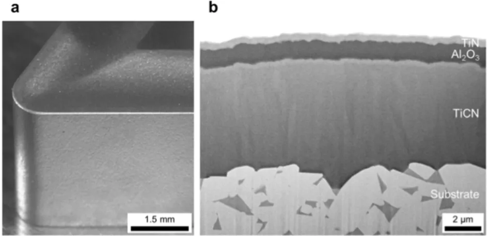
The cutting tools used for the turning tests were commercial CVD coated cemented carbide inserts for steel turning, TNMG160408, with a chip break-er as shown in Fig. 5a. The multilaybreak-er coating had about 7.2 μm TiCN as an inner layer, about 1.2 μm Al2O3 as an intermediate layer and about 0.6 μm
TiN as a top layer, see Fig. 5b. The cemented carbide substrate had a hard-ness of about 1450 HV.
Figure 5. (a) Appearance of an unused CVD coated carbide tool and (b)
cross-section of the tool.
39]. In recent years, Gerth et al. [35] employed a crossed cylinders sliding test. This kind of sliding test excludes the chip forming in the primary shear zone, and focuses on simulating only the contact between the chip and the rake face. The test was concluded to be capable of reproducing the transfer layers formed on rake faces on milling tools [35].
When PVD coated HSS tools are slid against a case hardening steel, ma-terial transfer is often divided into two regions; one dark colored transfer layer and one bright colored transfer layer, see Fig. 6. The dark transfer layer, defined as zone I, is an oxide strongly enriched with alloying elements of Al, Si and Mn from the steel, while the bright transfer layer, defined as zone II, is oxidized transferred steel. The dark transfer layer is dominating in the central region of the contact, where the contact pressure and the temperature are higher and the supply of oxygen from the environment is low. In contrast, the bright transfer layer is formed in the outer region of the contact, i.e. at low pressure, low temperature and a high oxygen supply. The dark transfer layer corresponds to the transfer layer dominating the contact area of the rake face in actual milling, and thus it is most important. In turning, most of the contact zone has no oxygen supply at all. However, the end of the con-tact zone has oxygen supply and similar transfer layers develop also there. In this thesis, this sliding test was utilized for studying the influence of oxi-dized transfer layer in zone I on friction and wear.
Figure 6. Backscattered electron image and EDS maps of a contact mark on a TiN
coated tool cylinder slid against the case hardening steel with the composition in Table 2. The contact mark comprises an alloy oxide (zone I) and an iron oxide (zone II).
2.3.1 Test setup
The work material was mounted in a lathe and the tool cylinder was placed in a holder and pressed against the work material, see Fig. 7. The small TiN coated HSS cylinder represented the rake face of the tool and the large rotat-ing steel work material cylinder represented the chip. Contact parameters such as normal load, sliding speed, contact mode (intermittent or continuous contact), etc. can easily be controlled [35, 40, 41]. The small cylinder was pressed with a normal load applied by a spring. This load is set sufficiently
high to cause substantial plastic deformation of the steels, to simulate the conditions on the rake face of a cutting tool. The friction force and normal load were measured throughout the test using load cells. The TiN coating always contacted the work material, while the work material entered the contact due to its rotating motion. In order to avoid repeated sliding in the same track on the work material, the small tool cylinder was moved using the feed of the lathe. This resulted in a contact more similar to that in actual machining. The sliding speed was measured from the number of revolutions and the diameters of work material cylinders.
Based on a previous study in the same test rig [40], concluding that the same type of oxide layer formed in both intermittent and continuous sliding, all tests in this work were performed in continuous sliding. The sliding test reproduces transfer layers formed mainly on the rake face of milling tools, not on the rake face of turning tools, even though the continuous sliding mode is used. In the sliding test oxygen enters the contacting surface as a thin oxide present on the surface of the work material, resulting in the for-mation of oxidized transfer layers very similar to those formed in milling.
Figure 7. Setup of the crossed cylinders sliding test.
2.3.2 Contact parameters
In Paper I, the sliding speeds and the normal loads were varied in the inter-vals 5–180 m/min and 25–200 N respectively, see Table 5. Generally the sliding speed and normal load were controlled to within 2.3 % and 1.8 % of their nominal values, respectively. For the slowest test, the speed differed more, about 5.2 m/min instead of 5 m/min. The total sliding distance was 3.1 ± 0.2 m, which was almost the same as that in the previous study [40]. The
formed. The varied contact parameters were normal load, sliding speed and work cylinder diameter. Only one of these three parameters was varied in each test series, keeping the other parameters constant. The varied parameter was normal load in series 1 and 2, sliding speed in series 3 and 4, and cylin-der diameter in series 5. Different constant sliding speeds were used in series 1 and 2, and different constant normal loads were used in series 3 and 4. The sliding speed was changed by adjusting the rotational speed of the work cyl-inder. The rotational speed was also adjusted in series 5 to make the sliding speeds the same when cylinders with different diameters were used. The sliding distance was kept almost the same for all tests by adjusting the slid-ing time.
In Paper II–IV, the normal load and sliding speed were 75 N and 100 m/min, respectively, see Table 7. Separate tests with different sliding times, 0.025, 0.05, 0.1, 0.3, 0.6, 1.2 and 1.8 s, were performed to study the initial transfer mechanisms. Also longer sliding times, 9.0, 18 and 36 s were used to investigate wear characteristics.
Table 5. Sliding test conditions in Paper I.
Test parameter
Sliding speed 5, 30, 45, 60, 90, 125, 180 m/min Normal load 25, 50, 75, 100, 125, 150, 200 N Sliding distance Approximately 3.1 m
Lubrication None (Dry) Atmosphere In air Temperature 21 ºC (RT)
Table 6. Sliding test series in Paper I.
Test
series Varied parame-ter Normal load [N] Sliding speed [m/min] diameter [mm]Work cylinder Sliding time [s] 1 Normal load 25, 50, 75, 100, 125, 150, 200 125 139 1.5 2 Normal load 25, 50, 100, 150, 200 60 139 3.1 3 Sliding speed 150 5, 30, 45, 60, 90, 125, 180 139 37.2, 6.2, 4.1, 3.1, 2.1, 1.5, 1.0 4 Sliding speed 50 5, 60, 90, 125 139 37.2, 3.1, 2.1, 1.5 5 Work cylinder diameter 50 125 54, 80, 110, 139 1.5
Table 7. Sliding test conditions in Paper II–IV.
Test parameter
Sliding speed 100 m/min Normal load 75 N Sliding distance Up to 60 m Test duration Up to 36 s Lubrication None (Dry) Atmosphere In air Temperature 21 ºC (RT)
2.4 Turning test
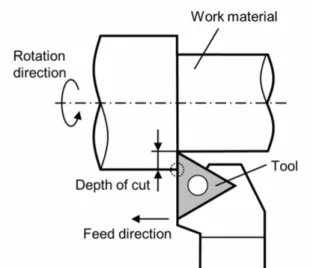
Material transfer and tool wear were studied also in turning operation (Paper V). The longitudinal turning tests shown in Fig. 8, using commercial CVD coated carbide inserts, were performed in a numerically controlled (NC) lathe with the cutting conditions shown in Table 8. Here, the part of the tool cutting through the surface of the work material cylinder, indicated by the dashed circle in Fig. 8, is called the region of depth of cut. For each steel, three separate tests with different cutting times, 1, 10 and 125 s, were made to study how the material transfer and wear changed with time. The cutting force was measured using a dynamometer during the 10 s cutting tests for each steel. Also chips were collected during the 10 s tests and their shapes were studied using optical microscopy.
Figure 8. Schematic illustration of the turning test. The region denoted “region of
Table 8. Cutting conditions in Paper V.
Test parameter
Cutting speed 250 m/min Feed rate 0.3 mm/rev Depth of cut 1.5 mm Test duration Up to 125 s Lubrication None (Dry)
2.5 Analytical techniques
2.5.1 Scanning electron microscopy (SEM)
An SEM with a field emission gun was used to observe surfaces and cross-sections of transfer layers and coatings. Either secondary or back scattered electrons were utilized for imaging. The acceleration voltage was 3, 10, 15 or 20 kV, resulting in different interaction volumes. For imaging of surfaces with thin transfer layers, the lower acceleration voltage (3 kV) was prefera-bly used to limit the information depth. The samples were sometimes tilted 65° to get more information about the surface topography of the transfer layers.
2.5.2 Transmission electron microscopy (TEM)
TEM, with a field emission gun and an acceleration voltage of 300 kV, was used for the cross-sectional studies of the transfer layers at high resolution. The observations were performed using bright field imaging and high-angle annular dark field scanning transmission electron microscopy (HAADF-STEM). Selected area electron diffraction analysis was performed to charac-terize the crystalline structures of transfer layers.
2.5.3 Energy dispersive X-ray spectroscopy (EDS)
EDS was employed in both SEM and TEM to analyze the chemical compo-sition of transferred material. When using SEM-EDS, the information depth is dependent on the acceleration voltage and the specimen materials. A low acceleration voltage, giving a small information depth, is desired to analyze thin layers of transferred material. However, the acceleration voltage needs to be high enough to excite the electrons in the elements to be analyzed. The acceleration voltage was selected considering both these aspects. When us-ing TEM-EDS, most of the incident electrons can transmit the thin film spec-imen prepared for TEM observation. Diffusion of incident electrons in the thin specimen is much less than that in a bulk specimen. This results in high-er spatial resolution in the TEM-EDS analysis than in SEM-EDS.
2.5.4 Focused ion beam (FIB)
A FIB instrument was used to make cross-sections of tool surfaces by Ga ion polishing. This instrument is equipped with an SEM column. With the SEM the appropriate area for observation is selected with micrometer precision and then a beam of Ga ion is used for polishing. The same instrument was also used to make thin film cross-sectional specimens for TEM studies, with the lift-out technique. Before preparing the cross-sections and TEM speci-mens, a platinum layer was deposited on top of the sample to protect its sur-face from the subsequent ion polishing process.
2.5.5 X-ray photoelectron spectroscopy (XPS)
XPS is a surface sensitive technique for chemical analysis. Only the top sur-face, up to 10 nm, can be analyzed, although the analyzed area is typically from several micrometers to millimeters in diameter. The bonding states of elements can be determined from the chemical shift in the spectrum. XPS was used to analyze very thin transferred material which were difficult to be clearly identified using SEM-EDS. Compositional depth profiles were rec-orded using stepwise material removal using Ar-ion sputtering with an ener-gy of 2 keV.
2.5.6 Auger electron spectroscopy (AES)
AES is another surface sensitive technique. Compared with XPS, AES gives higher lateral resolution, although it offers less information of bonding states. AES was employed to obtain element maps on thin transfer layers. It was also used to record depth profiles of selected small areas, using Ar-ion sput-tering.
2.5.7 White light interference profilometry
White light interference profilometry is an optical technique based on inter-ference of light, and gives a vertical resolution in the nanometer range and a lateral resolution in the micrometer range. This was used to measure the surface roughness of tool and workpiece materials, and the wear depths of tool materials.
2.5.8 Nanoindentation
Nanoindentation is used for surface sensitive hardness evaluation. The load and displacement are continuously measured during indentation with a
dia-this study, the hardness of the tool coatings was obtained using an indenta-tion depth of 200 nm. The hardness of the HSS substrate of used and unused coated cylinders was measured on polished cross-section with a load of 5 mN. Three-sided pyramidal Berkovich diamond tips were used for all meas-urements.
3. Effect of contact parameters on material
transfer in a sliding contact (Paper I)
The crossed cylinders sliding test can be used to simulate the material trans-fer mainly in milling as shown in Fig. 6. The formation and properties of the transfer layers are considered to depend on the operating conditions. The contact parameters in previous studies [35, 40, 41] were limited to quite nar-row ranges, simulating only certain cutting operations. In Paper I, with focus on oxide formation, the influence on material transfer from normal load, combined with different sliding speeds and work material diameters, was investigated. The case hardening steel, shown in Table 2, was slid against a TiN coated HSS with the contact parameters in Tables 5 and 6.
3.1 Influence on material transfer from normal load and
sliding speed
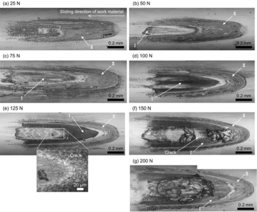
In the test series 1 of Table 6, a constant sliding speed of 125 m/min and different normal loads were used. At the low load of 25 N, zone II (light gray region) covered a relatively wide area, while zone I was not seen, see Fig. 9. As the load was stepwise increased to 100 N, zone II shrunk toward the rim of the contact mark, while zone I (black region) appeared in the inner region and expanded outwards. Zone I was mainly an alloy oxide including Al, Si and Mn, and zone II was an iron oxide containing small amounts of Si, Mn and Cr, as shown in Fig. 6. When the load was 125 N, a typical zone I was not seen in the very middle. Instead small cracks in the coating and substan-tial steel transfer appeared in the region marked with by the white rectangle. At 150 N, clear cracks and transferred steel lumps were observed. Cracks seem to promote transfer of steel from the work material. Further increase in normal load to 200 N resulted in huge metallic steel transfer.
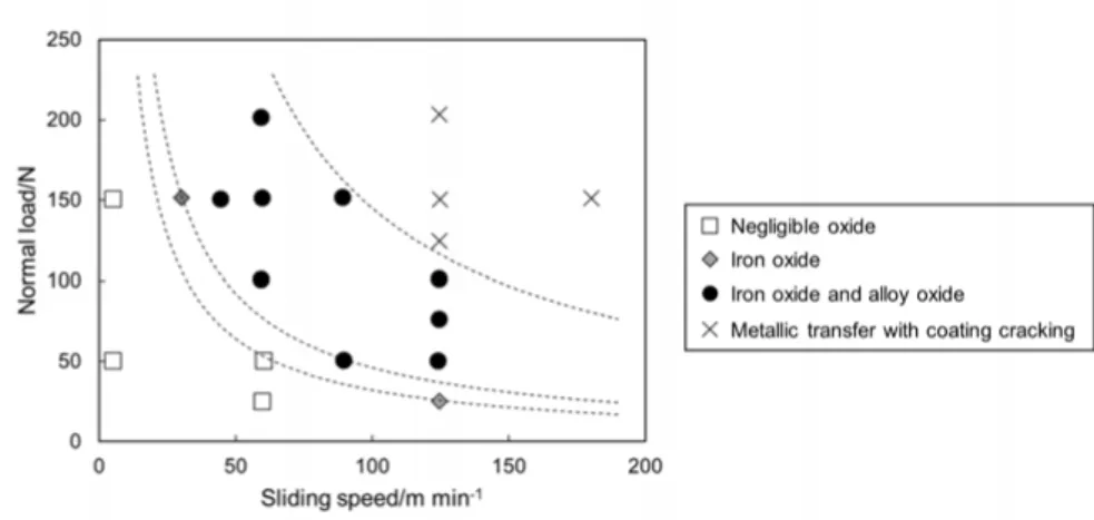
Experiments and analyses were performed also according to the other test series of Table 6, and the characteristic modes of material transfer are sum-marized in the sliding speed–normal load diagram in Fig. 10. Each test is mainly classified into one of four types of material transfer; negligible oxide, only iron oxide (zone II), iron oxide (zone II) and alloy oxide (zone I), and
Q=μWv
where Q, μ, W and v are the heat generation rate, the dynamic friction coeffi-cient, the normal load and the sliding speed, respectively [43]. Here, the friction coefficient was not considered, because the friction coefficient var-ied only slightly between the tests; always in the range 0.85–1.1 as long as the coating remained intact or only showed minute cracks. The iso-lines properly divide different modes of material transfer. This means that the heat generation, caused by an increase in normal load or sliding speed, is a domi-nant factor for the oxide formation and the coating cracking. An increase in heat generation will promote the generation and growth of oxide. However, a higher heat generation, than the coated tool can endure, leads to plastic de-formation of the substrate, as described in section 1.1.4 and Ref. [41], and destabilizes both the coating and the growing oxide.
The diameter of the work material cylinder in this test was confirmed to have no influence on the mode of transfer.
Figure 9. Contact marks on the TiN coated tool cylinders after sliding with a sliding
speed of 125 m/min and different normal loads against a work cylinder of a case hardening steel with a diameter of 139 mm. Black and light gray regions are indicat-ed by zone I and zone II, respectively. Cracks in the coating are indicatindicat-ed by arrows.
Figure 10. The characteristic modes of material transfer at different sliding speeds
and normal loads. Each test is classified into one of four types: negligible oxide formation, only iron oxide (zone II) formation, iron oxide (zone II) and alloy oxide (zone I) formation, and metallic transfer with coating cracking. The dashed lines are iso-lines of the heat generation estimated by a very simplified model.
3.2 Summary
The mode of material transfer and the occurrence of tool damage are strong-ly dependent on the normal load and sliding speed. The contribution from both parameters is explained by the heat generation in the sliding contact. The mode is classified into four types; negligible oxide, only iron oxide (zone II), iron oxide (zone II) and alloy oxide (zone I), and metallic transfer with coating cracking. The mode of iron and alloy oxide formation prevails in the broadest ranges.
4. Effect of single additions of Si, Mn, Cr and
Al on material transfer in a sliding contact
(Paper II, III)
The sliding test is used to evaluate material transfer, friction characteristics and coating damage of a TiN coated HSS against the model steels. To isolate and study the influence of the individual alloying elements, model steels were used, i.e. one base reference, only alloyed with C (Base steel), and four alloyed also with 1 mass% Si, Mn, Cr or Al, as shown in Table 3. The steels were slid against a TiN coated HSS cylinder with the contact parameters shown in Table 7.
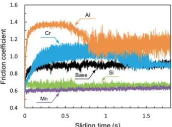
4.1 Friction characteristics
The five work material steels exhibited very large differences in friction behavior, see Fig. 11. Compared with the Base steel, the Si and Mn alloyed steels led to lower friction coefficient, while the Cr and Al alloyed steels resulted in higher. The friction coefficient against the Base steel, the Si al-loyed steel and the Mn alal-loyed steel rapidly stabilized and reached approxi-mately 0.9, 0.65 and 0.63 after 1.8 s, respectively. On the other hand, the friction coefficient against the Cr and Al alloyed steels changed drastically during the test. The friction coefficient against the Cr alloyed steel initially rose for about 0.15 s to a value of about 0.9, kept increasing slightly to reach about 1.05 after some 0.9 s, decreased gradually until about 1.5 s and then stabilized at about 0.9. Against the Al alloyed steel the friction coefficient initially increased for about 0.15 s to reach approximately 1.35, remained stable until about 0.5 s, then decreased gradually and finally stabilized at about 1.15.
Figure 11. Friction curves of the five model steels; the Base steel and the Si, Mn, Cr
and Al alloyed steels.
4.2 Surface appearance of tool cylinders and transfer
layer composition
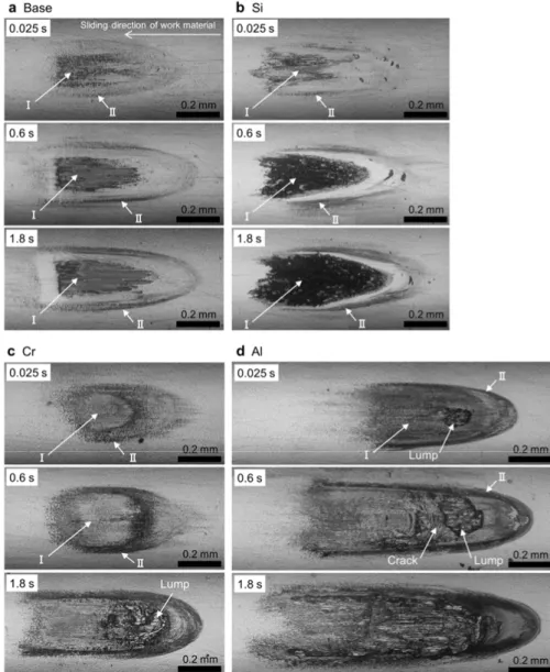
Already after 0.025 s, different types of transfer layers had formed in zone I on the TiN coated cylinders, and characteristic transfer layers developed during the first few seconds, see Fig. 12. When using the Base steel and the Si alloyed steel, zone I was almost fully developed already after 0.6 s and did not change much until 1.8 s. In fact, even after 18 s of sliding against the Base steel, the surface appearance was similar to that after 1.8 s and only very little wear of the coating was found (see Paper III for details). When sliding against the Cr alloyed steel, the area of zone I was fully developed after 0.6 s. After 1.8 s a large contact mark and a transfer lump were ob-served. This significant change of appearance was a result of cracking of the coating (clearly shown in Fig. 21). Using the Al alloyed steel, already after 0.025 s a large metallic lump was seen. After 0.6 s the transfer area had be-come broader and cracks were visible in the central area. After 1.8 s trans-ferred metallic steel covered almost the entire contact mark. The coating cracks and associated changes of transfer with the Cr and Al alloyed steels are consistent with the significant changes in the friction scatter occurring at about 1.5 s and 0.8 s in Fig. 11, respectively. Against these four steels, also another transfer layer was formed in a narrow region outside zone I, here denoted zone II. The present study focuses on zone I, not zone II, since zone I now covers a substantial fraction of the contact mark.
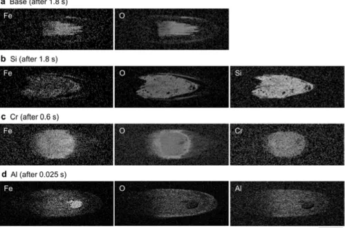
The EDS element maps in Fig. 13 show that zone I for all four steels con-tained Fe, O and the alloying element present in the steel having been tested.
Figure 12. Contact marks on TiN coated cylinders after sliding against (a) the Base
steel, (b) the Si alloyed steel, (c) the Cr alloyed steel and (d) the Al alloyed steel obtained in separate tests with different sliding times. The two different modes of transfer layer, transferred lumps and cracks of the coating are indicated by arrows.
Figure 13. EDS maps of the contact marks on the TiN coated cylinders after sliding
against (a) the Base steel, (b) the Si alloyed steel, (c) the Cr alloyed steel and (d) the Al alloyed steel.
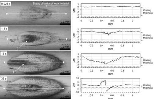
Compared to the other four steels, the Mn alloyed steel showed a different kind of transfer and wear behavior. After 0.025 s, only a very small amount of transferred material, and almost no wear, was found, see Fig. 14. After 1.8 s, some wear had occurred, reaching a maximum depth of approximately 1 μm. After 18 s sliding, the wear depth had increased to about 2.8 μm, much deeper than that for the Base steel. After 36 s, the wear depth exceeded the coating thickness and the most striking feature was found in the rear of the mark. An EDS analysis after 1.8 s sliding revealed the transfer layer of zone I contained Fe, O and Mn, but Mn was present only in a small amount (shown in Fig. 25).
Figure 14. Contact marks and wear of TiN coated cylinders after sliding against the
Mn alloyed steel obtained by separate tests with different sliding times. The surface profiles were obtained on the white lines in the images.
4.3 Transfer and damage of the coating slid against the
Base steel
The Fe–O transfer layer formed against the Base steel was homogeneous, see Fig. 15. FIB cross-sections in Fig. 16 revealed that the transfer layer was fully covering the coating surface and that the coating thickness was almost intact. This means that the continuous Fe–O layer protected the coating from wear. However a crack was seen after 18 s. The crack penetrated both the transfer layer and the coating, but stopped as it reached the substrate. At this point the coating on one side of the crack has been pressed into the substrate, and the substrate has deformed plastically. This plastic deformation of the substrate is possible because the friction heat has softened the substrate dur-ing sliddur-ing. This led to reduced support for the coatdur-ing, and subsequently to the generation of a few cracks through the coating.
Figure 15. The transfer layer formed against the Base steel after 1.8 s.
Figure 16. Cross-sections of the transfer layer formed against the Base steel after (a)
1.8 s and (b) 18 s. The difference in the thickness of transfer layers between 1.8 s and 18 s is more due to the difference of the observed position than due to the differ-ent times.
4.4 Transfer and damage of the coating slid against the
Si alloyed steel
The layer transferred from the Si alloyed steel developed in a more complex way and it could be divided into two regions; one rough and one smooth, see Fig. 17. The rough region consisted of a mixture of Fe–Si–O and metallic steel, and it was positioned in the central part of zone I. The metallic steel transfer occurred mainly due to the topography made by already formed Fe– Si–O. The front area exhibits smooth Fe–Si–O hills with minute grooves, and these hills actually surround most of the front edge, see e.g. the position of the white arrow in Fig. 17a. In the center, Fig. 17b, the transfer layer con-tained both higher and lower parts. The higher parts displayed very faint grooves along the sliding direction, as shown by the black arrows in Fig. 17c, while no such grooves were visible in the lower parts. This indicates that most of the rough region is not in contact with the sliding counter surface. Instead, the load is mainly supported by the smooth Fe–Si–O layer in the
Figure 17. SEM images of the transfer layer formed against the Si alloyed steel after
1.8 s, tilted 65°, showing the large topography. The white arrow in (a) indicates the smooth Fe–Si–O hills. The black arrows in (c) indicate fine grooves.
The transfer layer in the center area was around a micrometer thick, see Fig. 18a. In the front area the transfer layer consisted mainly of Fe–Si–O, con-taining small amounts of steel pieces, apparently distributed in layers, see Fig. 18b. In this region, the transfer layer was fully covering the coating and reached a thickness of approximately 6.4 μm. The continuous transfer layer will protect the coating from wear, as in the case of the Base steel.
Figure 18. Cross-sections in the transfer layer formed against the Si alloyed steel
after 1.8 s. The dark layer is Fe–Si–O, while the bright is metallic steel. The cross-sections were made in (a) the lower part of the center area and (b) the front area in the transfer layer.
4.5 Transfer and damage of the coating slid against the
Cr alloyed steel
The transfer from the Cr alloyed steel showed two modes, see Fig. 19, ap-parently mixed when viewed from above. The dark transfer layer was Fe– Cr–O, while the bright was metallic steel. The steel adhered on the front edges of the Fe–Cr–O transfer, which shows a strong contribution from the topography to the metallic steel transfer. In cross-section it is evident that an extensive Fe–Cr–O layer was covering the TiN coating and steel adhered on top of that, see Fig. 20. Within the entire analyzed cross-section, the Fe–Cr– O layer was rather thin, while the transferred steel was much thicker. After sliding for 1.8 s, cracks had formed in the coating and transferred steel was associated with the cracks, see Fig. 21. The cracks were caused by substrate softening, as described for the Base steel. However, the coating damage was more severe when sliding against the Cr alloyed steel, as it gave higher fric-tion and generated more heat.
Figure 19. The transfer layer formed against the Cr alloyed steel after 0.6 s. Dark
Fe–Cr–O and bright metallic steel transfer layers are indicated by black arrows.
Figure 20. (a) Cross-section image and (b) EDS maps in the transfer layer from the
Figure 21. (a) The entire material transfer region after sliding against the Cr alloyed
steel for 1.8 s and (b) magnification of the area marked with the white rectangle in (a). Cracks in the coating and the steel transfer along the cracks are indicated by black arrows.
4.6 Transfer and damage of the coating slid against the
Al alloyed steel
Apart from the obvious difference between the lump and the rest of the con-tact, the transfer from the Al alloyed steel had occurred in two different modes after 0.025 s, see Fig. 22. The magnified image from the center and the two corresponding AES maps show that the dark transfer layer, indicated with the letter “D”, was Al-rich while the bright transfer layer, indicated with the letter “B”, was Fe-rich. The local Fe-rich transfer tended to initiate at the front edges of the Al-rich transfer layer, as exemplified in the area within the white dashed rectangle in the front image. A cross-section TEM study in the center area reveals that an Al-rich transfer layer, several tens of nm thick, was covering the TiN coating surface, see Fig. 23. To the left in the image an Al-rich “hill”, some 70 nm high, was visible, and on its front edge an approximately 170 nm thick Fe-rich transfer layer has been attached. The EDS spectra show that the Al-rich transfer layer was almost pure Al–O as the Al was very dominant over Fe, while the Fe-rich transfer layer was metallic steel.
The local transfer mechanism from the Al alloyed steel is as follows, based on Figs. 22 and 23. First, a thin oxide layer is formed on the TiN coat-ing. Subsequently, metallic steel is transferred in front of and on top of it. This metallic steel transfer is promoted by the roughness caused by already transferred oxide. This process results in a rough steel-to-steel contact, which finally allows the large metallic steel lump to form.
Figure 22. (a) SEM images of the transfer layer formed against the Al alloyed steel
after 0.025 s. A white dashed rectangle in the front image indicates an area with an Fe-rich transfer layer attached to the front edge of an Al-rich transfer layer. (b) AES maps in the center area. The letters “B” and “D” in the center image and maps repre-sent the bright Fe-rich transfer layer and the dark Al-rich transfer layer, respectively. After sliding for 0.6 s against the Al alloyed steel, cracks in the coating were seen as in Fig. 12d. The cracking was caused by substrate softening, analo-gous to the cases of the Base steel and the Cr alloyed steel, as shown in Figs. 16 and 21. However, the coating damage against the Al alloyed steel, which gave the highest friction, was more severe than against the Base steel and the
contact, see Fig. 24a. In this region, severe deformation and cracking of the coating occurred, although it was not worn. The presence of white etching layers indicates that the substrate microstructure underneath the coating transformed into mainly soft austenite during the sliding due to the high fric-tion induced temperature. It could not support the coating and caused coating deformation, fracture and tilting of the fragments.
Figure 23. (a) TEM bright field image and EDS maps of a cross-section in the center
area of the transfer layer formed against the Al alloyed steel after 0.025 s. (b) EDS spectra from the Al-rich and Fe-rich transfer layers.
Figure 24. Polished cross-section of the tool cylinder after sliding against the Al
alloyed steel for 0.6 s. The cross-section, showing the central part of the contact mark, was etched with nital. The white etching layer (WEL), and the deformation and cracks of the coating are shown by arrows. (b) SEM image showing the coating cracking and metallic steel transfer in the white rectangle of (a).
4.7 Transfer and damage of the coating slid against the
Mn alloyed steel
After 1.8 s, the bottom of the wear mark showed many grooves and streaks of transferred material formed along the sliding direction, see Fig. 25. In contrast to other steels, this transferred material was not fully covering the coating. Instead it was non-continuous and the edges of individual streaks of it had a fractured appearance. After 36 s, the wear depth exceeded the coat-ing thickness, as shown in Fig. 14. In the worn region around the center of the contact mark, the coating has been removed and steel has adhered on the exposed substrate, as in region B of the FIB cross-section in Fig. 26. In re-gion C, the worn TiN coating was cracked but remained as fragments pressed into the substrate. In region D, the coating was not yet cracked but worn from its original thickness of about 3.6 μm to a thickness of about 1 μm. These results indicate that non-continuous transferred Fe–Mn–O did not protect the coating from wear, causing continuous coating wear. The grooves on the worn surface shown in Fig. 25a suggest that abrasion caused by hard inclusions, such as aluminium oxides, in the steel was one of the main wear mechanisms.
Figure 25. (a) The transferred material from the Mn alloyed steel after 1.8 s. In the
upper right image, the bright area indicated by the black cross A is transferred Fe– Mn–O, while the dark area indicated by the white cross B is the TiN coating surface. (b) EDS spectra of the Fe–Mn–O (A) and the TiN coating (B) obtained at the crosses
Figure 26. Cross-section of the worn region in the center of the contact mark after
sliding against the Mn alloyed steel for 36 s, showing continuous wear of the coating and the exposed substrate.
4.8 Friction and coating damage mechanisms
The five steel compositions resulted in different modes of material transfer in the center of the contact. The modes influenced the friction coefficient as well as the coating damage, as summarized in Table 9. The damage mecha-nism of the TiN coated HSS tool is chiefly determined by the form of the transfer layer and friction coefficient. Continuous wear occurs only when a non-continuous transferred material, which gives no protective effect, is formed, i.e. Fe–Mn–O. In all other cases, the substrate softening caused by the friction heat is responsible for coating deformation, cracking and fracture. The severity of the coating damage is dependent on friction heat and thus on the friction coefficient. This means the continuous transfer layer which gives low friction, i.e. Fe–Si–O, provides the protective effect and prolongs the life of coating.
Table 9. Summary of results in Paper II and III. COF means friction coefficient at
the stable stage.
Transfer layer
COF Coating damage
Composition Form Cracking Wear
Base Fe–O Continuous 0.9 Crack generation No wear Si Fe–Si–O Continuous 0.65 Slow crack generat-ion No wear Cr Fe–Cr–O Continuous 1.05 Rapid crack gene-ration (1.8 s) No wear Al Al–O Continuous 1.35 Rapid crack gene-ration (0.6 s) No wear Mn Fe–Mn–O, with Mn in small amount continuousNon- 0.63 No crack Continuous wear When the transferred material has a continuous form, the work material pre-dominantly slides against the transferred material. Therefore, the friction coefficient is decided mainly by the shear strength of the interfacial region between the transfer layer and the work material, at the elevated temperature.
![Figure 3. Cross-section of the transfer layer on the rake face of a coated HSS hob cutting tooth [2]](https://thumb-eu.123doks.com/thumbv2/5dokorg/5460775.141823/17.727.211.515.612.841/figure-cross-section-transfer-layer-coated-cutting-tooth.webp)