Mammography
– recent technical developments
and their clinical potential
2002:08 BENGT HEMDAL, INGVAR ANDERSSON, ANNE THILANDER
KLANG, GERT BENGTSSON, WOLFRAM LEITZ,
SSI rapport : 2002:08 maj 2002
ISSN 0282-4434 FÖRFATTARE/ AUTHOR: Bengt Hemdal1, Ingvar Andersson2, Anne Thilander
Klang3, Gert Bengtsson4, Wolfram Leitz5, Nils Bjurstam6, Olof Jarlman4 and Sören Mattsson1
1 Department of Radiation Physics, Malmö University Hospital, 2 Department of Diagnostic Radiology,
Malmö University Hospital, 3 Department of Medical Physics and Biomedical Engineering, Sahlgrenska
University Hospital, 4 Department of Diagnostic Radiology, Lund University Hospital, 5 Swedish
Radia-tion ProtecRadia-tion Authority, 6 Centre for Breast Imaging, Department of Radiology, University of North
Norway, Troms
AVDELNING/ DIVISION: Avdelningen för personal- och patientstrålskydd / Depart-ment of Occupational and Medical Exposures
TITEL/ TITLE: Mammography – recent technical developments and their clinical potential SAMMANFATTNING: Syfte: Att gå igenom den senare tidens utveckling i röntgentek-nik för mammografi med både digital och skärm-film tekröntgentek-nik för att utvärdera deras kliniska potential och analysera möjliga framtida utvecklingsmöjligheter.
Material och metoder: Den vetenskapliga litteraturen har gåtts igenom, konferenser
har bevakats och kontakter med kollegor har utvecklats. Företag inom verksamhet-sområdet har lämnat uppgifter och blivit inbjudna för presentationer. Egen erfarenhet har samlats av olika mammografiutrustningar med skärm-film och digital teknik.
Resultat och slutsatser: Trots tillgången till viktiga kompletterande tekniker som
ultraljud och magnetkamera (MR eller MRI), är röntgentekniken mammografi fort-farande standardteknik för medicinsk avbildning av bröst. Den är relativt enkel och kostnadseffektiv, och är den för närvarande enda realistiska tekniken för storskaliga hälsoundersökningar. Fortfarande är det i stort sett den enda metod, med vilken man kan upptäcka icke invasiv bröstcancer.
Utrustning för digital mammografi är kommersiellt tillgänglig både med liten yta och med fullfältsteknik (FFDM). Utvecklingen av FFDM utrustningar är nu intensiv, liksom utvecklingen av anpassade arbetsstationer och datorstödd diagnostik (CAD). Trots detta har introduktionen av digital mammografi varit mycket långsam jämfört med de flesta andra röntgenundersökningar p g a höga kostnader och tekniska pro-blem vad gäller de höga kraven på bildkvalitet och dos i mammografi liksom kraven på anpassat arbetsflöde vid hälsoundersökningar och lämpliga presentationsformer. Granskning på ljusskåp av utprintade filmbilder från digitala mammografiutrust-ningar har hittills varit det vanligaste granskningssättet, men för att kunna utnyttja den digitala tekniken full ut, diagnostiskt såväl som logistiskt, måste bildgranskning på monitor tillämpas.
FFDM teknik har potential för signifikant bättre bildkvalitet eller signifikant lägre stråldos än skärm-film teknik (SFM), eller båda delarna. Det krävs ytterligare forsk-ning och utveckling för att helt kunna utnyttja denna potential.
Investeringskostnaderna är mycket högre för digital än för skärm-film mammografi idag. Icke desto mindre kommer digital mammografi högst sannolikt att ersätta skärm-film mammografi i stor utsträckning, särskilt i storskaliga tillämpningar. Fort-satt utvärdering av digital och skärm-film mammografi måste genomföras vad gäller bildkvalitet och stråldos liksom diagnostiskt utbyte i form av sensitivitet, specificitet och kostnadseffektivitet. Frågan är huruvida de högre investeringskostnaderna upp-vägs av ökad sensitivitet och specificitet, mer rationell hantering och lagring, samt av möjligheterna att använda nya tekniker för framställning och analys av bilder.
Den framtida användningen av mammografiteknik kommer förmodligen att variera, med tillgång till olika slags digital teknik och även fortsatt användning av skärm-film, beroende på patientvolym och medicinska såväl som ekonomiska aspekter. SUMMARY: Purpose: The recent technical developments in digital as well as screen-film X-ray mammography have been reviewed in order to evaluate their clinical po-tential and to analyse possible lines for future development.
Material and methods: The scientific literature has been reviewed, conferences
in-quired and invited for presentations. Own experience has been gathered from diffe-rent screen-film and digital mammography systems.
Results and conclusions: Although there are important complementary
techni-ques such as ultrasound and magnetic resonance imaging (MRI), X-ray mammo-graphy is still the golden standard for breast imaging. It is relatively simple and cost-effective, and it is presently the only realistic technique for screening in a large scale. It is still largely the only technique that can detect breast cancer in a preinva-sive stage.
Equipment for digital mammography is commercially available both with small area and full field technique (FFDM). The development of FFDM systems is now intense, as well as the development of dedicated workstations and computer-aided detection (CAD). In spite of this, the introduction of digital mammography has been very slow compared to most other X-ray examinations due to high costs and technical challen-ges to meet the high demands on image quality and dose in mammography as well as the demands on specialised workflow support for screening mammography and sui-table display techniques. Film reading of digital mammograms has been the most common display mode so far, but to take full advantage of the digital concept, diag-nostic as well as logistic, monitor reading must be applied.
There is a potential of FFDM systems for significantly higher image quality or sig-nificantly lower dose than screen-film mammography (SFM), or both. Further re-search is necessary to fully use this potential.
The investment costs are much higher for digital than screen-film mammography today. Nevertheless digital mammography will most likely replace screen-film mammography to a large extent, especially in large-scale operations. However, further evaluation of digital and screen-film mammography must be performed re-garding image quality and dose as well as diagnostic outcome in terms of sensitiv-ity, specificity and cost-effectiveness. The question is whether the higher investment costs are outweighed by increased sensitivity and specificity, more rational hand-ling and storing, and the possibilities to use new techniques for image production and analysis.
The future use of mammography technique will probably be varying, with the avai-lability of different kinds of digital techniques and also the continued use of screen-film, depending on the patient volume and medical as well as financial aspects.
Författarna svarar själva för innehållet i rapporten.
The conclusions and viewpoints presented in the report are those of the author an do not necessarily coincide with those
Mammography –recent technical
developments
and their clinical potential
Content
ABBREVIATIONS
2
INTRODUCTION
2
BACKGROUND
2
DEVELOPMENT OF CONVENTIONAL MAMMOGRAPHY
3
CLINICAL MAMMOGRAPHY AND SCREENING
3
ALTERNATIVE AND COMPLEMENTARY TECHNIQUES
3
SCREEN-FILM TECHNIQUE
4
IMAGE QUALITY AND DOSE
7
SENSITIVITY AND SPECIFICITY
8
COST-EFFECTIVENESS
8
DEVELOPMENT OF DIGITAL MAMMOGRAPHY
8
INDIRECT DETECTION TECHNIQUE
9
DIRECT DETECTION TECHNIQUE
12
DIRECT PHOTON COUNTING TECHNIQUE
13
POST PROCESSING AND DISPLAYING
16
ARCHIVAL AND RETRIEVAL
18
SPECIAL TECHNIQUES IN DIGITAL MAMMOGRAPHY
18
IMAGE QUALITY AND DOSE
19
CLINICAL POTENTIAL OF DIGITAL MAMMOGRAPHY
20
CONCLUSIONS
21
ACKNOWLEDGEMENTS
22
PRELIMINARY REPORTS
22
REFERENCES
22
Abbreviations
aSe aSi AEC AGD ASIC amorphous selenium amorphous siliconautomatic exposure control average glandular dose
application specific integrated circuits CAD CCD CMOS CR computer-aided detection charge-coupled device
complimentary metal-oxide semiconductor computed radiography DM DQE FDA FFDM digital mammography detective quantum efficiency
Food and Drug Administration, USA full-field digital mammography HRT MRI MTF OD PACS PMA PMMA RAM RIS SF
hormone replacement therapy magnetic resonance imaging modulation transfer function optical density of a film
picture archiving and communication system premarket approval
polymethyl methacrylate random access memory radiology information system screen-film SFM SNR TDI TFT screen-film mammography signal to noise ratio
time delay integration thin film transistor
Introduction
Mammography is one of the most frequent X-ray examinations, until now dominated by screen-film (SF) technique, however, challenged by digital mammography (DM). The technique shift has been expected for a long time, and since the analogue and digital techniques are different in many aspects, it was considered necessary to review the current situation and lines of development to be able to better foresee needs in future radiation protection actions. In a research project from the Swedish Radiation Protection Authority (P 1062.98), the recent technical developments of DM and their clinical potential has been studied in the light of developments of the conventional SF technique.
As a background to this report we have reviewed the scientific literature, covered conferences in the field and developed contacts with manufacturers and colleagues. Comparative measurements have been carried out on different mammography systems.
Background
Particularly during the last two decades, mammography has experienced an enormous expansion and in many countries it is one of the most frequent X-ray examinations, especially in Sweden [Leitz 1997] and other countries with nation-wide screening programs, e.g. the Netherlands, the United Kingdom, Finland and Australia. Screening mammography is in progress also in other European countries as for instance Norway, as well as in Canada and the USA. In 1982 there were only 134 mammography units in the USA, increasing to about 10 000 in 1990. The present annual number of mammographic examinations in
The frequent use of mammography and the large proportion of screening examinations has inspired a lot of effort in optimising the current technique, still dominated by screen-film. National [Socialstyrelsen 1998] and international [EC 1996a, Zoetelief et al. 1996, EUROATOM 1997] recommendations and legislation’s have been especially dedicated to mammography, in some cases together with other frequent X-ray examinations [EC 1996b].
Since the mid 90´s there has been a great interest in digital mammography, but the shift from screen-film to digital mammography has been slowed down by technical challenges and high costs due to the demands on high image quality and low absorbed dose in mammography. Both in clinical mammography and especially in screening, digital mammography is still uncommon. The purpose of this work is to evaluate the technical development and the clinical potential of digital mammography compared to screen-film technique. As a background, the development of conventional mammography is described briefly.
Development of conventional mammography
Mammography with screen-film technique is fast and cost-efficient, with high sensitivity and specificity, which are important requirements for any screening activity. It is consequently not easy for a new technique like digital mammography to compete. However, there are limitations of screen-film
mammography (SFM) that digital technique has a potential to remedy. Examples of important limitations are a limited dynamic range, a fixed display scale with low image contrast in the dense breast parenchymal area and environmental problems from chemicals in the processor. The efficiency to transfer information from the spatial distribution of X-ray quanta behind the breast to an image is described with the quantity detective quantum efficiency (DQE). The relatively poor DQE of screen-film techniques indicate a potential for improvement of the image quality and/or a reduction of the dose with digital systems.
Clinical mammography and screening
Screening mammography differs from clinical mammography quantitatively rather than qualitatively. The large number of cases handled per time unit in screening implies special demands on rational processing including display, reading and storage of the images. The field size of present “full-field” mammography units is usually about 18 cm x 24 cm with an option to use 24 cm x 30 cm for large breasts. In clinical mammography there is also a need for imaging a small area (about 5 cm x 5 cm) with magnification of the image with a factor of about 1.7-2.0. This should also be possible to combine with a biopsy needle
guidance system in stereotactic mode.
Alternative and complementary techniques
There are a lot of techniques available for breast diagnosis, some of which are at the experimental stage. Although new breast imaging techniques are emerging and techniques such as ultrasound and magnetic resonance imaging (MRI), represent significant contributions, mammography is still the golden standard. There are several reasons for this, one being its relative simplicity, another its cost-effectiveness.
Mammography is presently the only realistic technique for screening in a large scale. It is still largely the only technique that can detect breast cancer in a preinvasive stage.
It has to be remembered that the final arbiter whether a lesion is benign or malignant cannot be imaging, but has to be cytology and histology. Therefore, the standard diagnostic battery in breast diagnosis is mammography, ultrasound, physical examination and needle biopsy.
The main complementary imaging techniques to mammography are ultrasound and MRI, which both have the advantage of not using ionising radiation. The advantages of ultrasound are mainly that it is relatively inexpensive and that it works well also for dense breasts where mammography has difficulties. Ultrasound also plays an important role as guidance for needle biopsy. MRI should be performed as a contrast
enhanced dynamic study and is then a very sensitive and moderately specific technique, which may provide unique information. Certain indications are already established, such as the investigation of unclear findings on conventional examinations, including multifocal malignant disease. Other established indications are the investigation of the postoperative/postirradiated/augmented breast and the work-up of
patients with metastatic disease in the axilla and negative conventional examinations. Other indications such as screening of the high-risk patient are not yet established.
Among more infrequent techniques are computed tomography (CT), scintimammography with 99Tcm sestaMIBI (Cardiolite) or 111In octreotide, positron emission tomography (PET) with 18F DG or 11C methonine, transillumination, elastography, electric impedance imaging and thermography. None of these techniques represent any realistic alternative to mammography in large-scale breast imaging, but can be used as complementary techniques.
Screen-film technique
The mammographic technique has been improved continuously since the introduction by pioneers such as Raoul Leborgne in Montevideo, Uruguay in the 1940´s [Leborgne 1951]. Modern mammography was developed by Charles Gros in France in the 1960´s. The revolutionary features were an X-ray tube optimised for soft tissue imaging with a molybdenum (Mo) anode, a Mo-filter and a compressing device. This type of unit and the introduction of rare-earth intensifying screens in the mid 1970´s were important for the enormous expansion of mammography during the last two decades. The technical evolution of mammography has continued. Reviews on the physics of modern screen-film mammography techniques have been made elsewhere [Barnes 1999, Haus 1999, Hendrick and Berns 1999].
Here follow a short discussion on screen-film (SF) technique with comments on digital mammography (DM):
X-ray unit
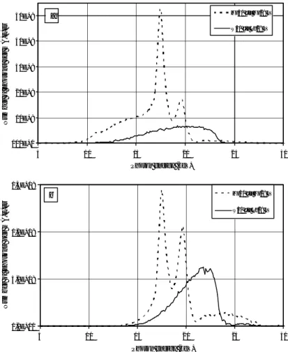
Modern X-ray units usually have electrical motors that facilitate for example height adjustments and angulations. It has also highly developed ergonomics. Many special features have been developed in order to rationalise the work of image acquisition; a recent example is a moveable X-ray tube from
Instrumentarium, Figure 1, for improved access to the patient.
Comment DM: Using imaging plates and some other DM systems, conventional mammography X-ray units can be used, while e.g. scanning digital radiology systems must have a special X-ray unit.
Ergonomics are important also with DM, but for some systems, e.g. the more space demanding scanning systems, it could be more difficult to develop an X-ray unit with good ergonomics.
X-ray tube
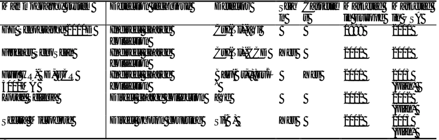
Most current mammography systems have Mo-anodes combined with Mo-filtration, many in addition have rhodium (Rh) filtration. Some manufacturers also offer dual-anode tubes, such as Mo-Rh, General Electric, or Mo-W (tungsten), Siemens. The combination of Mo anode with Mo filtration produces a photon energy distribution, which is rather close to optimal (at least for an X-ray beam) for imaging small to medium sized breasts at tube potentials between 25 and 30 kV. Increasing the tube potential increases the penetration of the beam and thus decreases the mean absorbed dose. However, this also decreases image contrast by decreasing the attenuation differences. Switching to Rh-filtration as well as Rh- or W-anodes has the same effect [Thilander Klang 1997]. In Figure 2 examples of X-ray spectra illustrate the difference between the energy distribution of incident and transmitted photons for a breast simulated with 40 mm polymethyl methacrylate (PMMA). The information content is highest for low energy photons penetrating the breast, and the photons not transmitted will result in absorbed dose to the patient, which applies to all the photons below about 13-15 keV. It is evident from Figure 2 that e.g. the anode/filter combination W/Rh results in higher mean energy of transmitted photons than Mo/Mo at the same tube potential.
Many modern mammography units have programs which automatically choose tube potential as well as filter, in some cases also anode on the basis of breast thickness (input from the compression device), sometimes also breast composition (input from the “AEC”, see below). The combination choosen should represent a reasonable compromise between image contrast and dose, so that the dose is not unnecessarily high for the imaging task [EURATOM 1997].
The tube current must be adequate to produce proper optical density (OD) of the film within a short exposure time. Exposure times over about one second imply a risk of added dose from reciprocity law failure. The tube current should be at least 80 mA, preferably 100 mA. Rh anodes cannot be operated at as high tube current as Mo and W-anodes due to a lower melting point.
Comment DM: Digital detectors usually have a different response to X-rays than SF. Somewhat higher energies are generally used and modern X-ray tubes that are used for the conventional SF technique can be well suited also for DM, as e.g. in the case of GE Senographe 2000D. However, since the image can be post processed, the selection of X-ray energies with DM is not as critical as with SFM. A replacement of the X-ray tube could however be needed for other reasons, e.g. for scanning systems with high demands on heat loading capacity. With image plates the optimum combinations of anode/filter and tube potential seems to be rather similar to those of screen/film. Reciprocity law failure does not exist for digital detectors, but a reasonable exposure time is desirable for other reasons, e.g. less risk of motion
unsharpness and better comfort for the patient. Scanning systems usually have an exposure time as long as about 5 seconds, which is a disadvantage.
Scatter control
One important factor degrading image contrast is scattered radiation. The amount of scatter depends heavily on breast thickness and to some extent also on the area covered by the compressed breast. Compression reduces scatter and make the level of scatter more even. This is one of the reasons why breast compression is necessary to obtain a good mammogram with SF technique. Further effect can be obtained locally by compression of a smaller area, so-called spot compression, which can be combined with magnification and a smaller radiation field area.
The most important part of scatter reduction is the anti-scatter grid. Such a grid consists of thin lead lamellae separated by a radiolucent spacer. The grid ratio (height of lead lamellae divided by interspace thickness) is usually 4:1 or 5:1. The grid should be moving during the exposure. The effect of the grid is to absorb a major part of the scattered radiation (75-85%) while transmitting a major proportion of the primary radiation (60-75%) [Barnes 1999]. As a result, image contrast is improved at the price of increased dose. Contrast improvement is related to breast thickness (as with scattered radiation), being larger with thicker breasts.
Conventional linear grids reduce scatter efficiently only perpendicular to the grid septa, while there is little reduction in the direction parallel to the grid lines. Another solution is the cellular grid from Lorad (Figure 3), which has a square pattern and therefore controls scatter in two dimensions. These grids have been shown to further reduce scattered radiation [Rezentes et al. 1999] and thus to further improve image contrast compared to conventional grids without dose increase, if anode/filter Mo/Mo and tube potential 25-30 kV is used.
An even more efficient way of reducing scatter is the slot scanning technique. The X-ray beam is collimated to a thin fan beam, which is scanned across the breast.
Still another way of reducing scatter is geometric magnification using an air gap. The magnification factor is usually 1.7 -2.0. For magnification work a microfocus of nominal size 0.10 - 0.15 mm is necessary. Thus, mammography units that are used for work up (and not only screening) should be equipped with a microfocus.
Comment DM: Scatter increase the noise also in DM, but scatter control is less important than in SFM, mainly because the image can be post processed. Therefore, contrast deterioration from scattered radiation can at le ast partly be compensated for. The anti-scatter grid is used in e.g. GE Senographe 2000D, but is actually not needed for small or medium sized breasts [Veldkamp et al. 2001]. The slot scanning technique is used with Fischer SenoScan and Sectra Microdose. Digital systems usually use zooming instead of geometric magnification, and therefore not the air-gap technique.
Compression device
Optimal compression is a very important part of the mammography procedure. Compression improves contrast by reducing both the scatter and the mean energy of the X-ray photons penetrating the
compressed tissue. Compression also reduces the dose to the breast. The motion of the breast is also reduced. Furthermore, the OD of the mammogram becomes more uniform. By proper compressio n, the structures of the breast are spread apart which makes image interpretation easier.
A refinement of the compression is the bi-directional compression system, which takes into consideration the natural mobility of the breast. This should make it possible to include more of the juxtathoracic part of the breast in the imaging field. The same effect may be obtained with moving radiolucent sheets, which pull the breast into the imaging field during compression. Both techniques, provided by Planmed, are illustrated in Figure 4.
Comment DM: Because of the wide dynamic range, the firm compression necessary in SFM
mammography has not the same importance for the image quality, especially not in cases where the scattered radiation is practically eliminated, as with the scanning systems. It must however be stressed that compression is important also with DM because of the reduction of breast motion and the separation of structures of the breast. An exception to this is tomosynthesis (explained below). Also DM systems must include as much as possible of the juxtathoracic part of the breast in the imaging field. Special observation on this is motivated with DM systems, because of the space that might be needed for electronics at the edges of the detector.
Automatic exposure control
Proper AEC-operation is essential to get optimal and reproducible OD of the films independent of breast thickness and beam quality used. AEC-devices have one or several sensors beneath the cassette, with the main function to stop the exposure at the right moment (i.e. resulting in a proper OD). The high-contrast screen-film systems used in mammography have a very limited exposure range, which put high demands on the AEC. The tendency in recent years of higher output of the X-ray tubes and higher sensitivity of the screen-film systems, results in a short and low signal from the AEC detector, which makes the task even more difficult. The sensor should have a certain size and should be possible to move away from the chest wall. The reason for this is that the exposure should be determined by the densest part of the breast. The AEC should meet certain standards, which may vary. One requirement is that the AEC should maintain a uniform film optical density to +/- 0.10 or 0.15 OD units when the thickness of the phantom varies from 2 to 7 cm PMMA for all techniques used [EC 1996a].
The AEC have been refined substantially during the last years. A novel AEC design has been presented by Instrumentarium using 8 detectors, optimised in size, location and shape, Figure 5. The most suitable detector can be automatically chosen at the beginning of the exposure from the detector with the lowest signal. In this way the densest part of the breast will always be properly exposed.
AEC sensors could also have a sandwich design with filters, and a dual signal from the detector could be used for an estimation of the radiation quality behind the breast, and thus a measure of the breast
composition. In this way the AEC could provide information for the automatic change of tube potential as well as filter, in some cases also anode, during the exposure (see “X-ray tube” above).
Comment DM: With DM the exposure level is not that critical. It must still be balanced carefully between image quality and dose, but “under”- or “over”- exposure will result in more or less noise, but probably not ruin the image, as with screen-film. This is one important advantage of DM, which will reduce the frequency of retakes. Instead, there is a risk for unnecessarily high doses, because the image quality will improve with increased exposure. Another important difference from SF is that the AEC detector can be the same as the entire image detector, as in the full-field digital mammography (FFDM) system
Senographe 2000D from General Electric (see below). With scanning systems the exposure level has to be determined in advance, and AEC is not used.
Screen-film and processing
The dose has been reduced rather dramatically during the last decades from the originally used direct film technique, over the vacuum-cassette technique to the present cassette technique with the use of new efficient phosphors in the intensifying screens. At the same time, the image contrast has been dramatically improved, and the image latitude decreased. The introduction of rare earth intensifying screens in the mid 1970´s represented a major step forward. These screens could be combined with high-speed films
reducing the dose. The screens are virtually always used as back-screens combined with a single -emulsion film in order to achieve optimal spatial resolution. Various phosphors have been used; one commonly used is gadolinium-oxysulfide (Gd2O2S:Tb) emitting visible light in the green spectral region (wave-length
about 500 nm).
Film processing is a critical link in the chain leading to a high quality mammogram. Sub-optimal image quality is frequently due to sub-optimal processing. The processing is one of the key factors determining the film contrast and the absorbed dose. Critical factors in the processing are temperature, processing time and replenishment rate.
Comment DM: The basic idea of DM is to get rid of screen-film-processing, its limitations and variability. However, several other possibilities and problems occur, which will be discussed further.
Viewing conditions
Viewing conditions are of greater importance than generally appreciated. Light boxes of adequate luminance (2000-6000 cd/m2) and reading conditions with a low level of ambient light (<50 lux) are important as well as masking of the films to reduce stray light [EC 1996a].
Comment DM: Viewing conditions are important for DM as well as for SFM. Display luminance of a monitor should be adequate (at least about 300 cd/m2) and the ambient light should be limited (<50 lux, dependent of the luminance).
Image quality and dose
The goal in mammography is to consistently produce sufficiently high quality mammograms with minimal radiation exposure to the patient. Image contrast and spatial resolution are important determinants of image quality in mammography.
One of the restrictions of SFM is its limited dynamic range. The characteristic S-shaped Hurter and Driffield (HD) dose response curve means that the contrast is high for intermediate exposure areas but low for both low and high exposure areas in the so called toe and shoulder of the curve. In other words,
“dense” and “thin” areas of the breast are displayed with low contrast.
Low contrast in the thin areas of the breast, i.e. the black areas of the film, means that the skin line and nearby subcutaneous structures often are difficult to see, except when using a bright light. However, it is unusual for breast cancer to have its epicenter in the subcutaneous area.
Most important are the dense areas, where cancers are most difficult to detect. In these more or less white areas of the film a breast cancer usually is found from signs like spiculations, calcifications and
architectural distortion. To find breast cancer with no other sign than a mass in a dense breast parenchyma can be as difficult as finding a snowball in a snowdrift. The increased use of hormone replacement therapy (HRT) in recent years tends to make this problem worse [Kavanagh et al. 2000]. Screening of younger women also highlights this problem. Improved contrast above all in the imaging of the dense part of the breast could significantly improve the detectability of breast cancer.
The average glandular dose (AGD) in the breast per mammogram is in the order of 1 mGy for the average breast using state of the art equipment, e.g. in Sweden [Leitz and Jönsson 2001]. The dose
recommendations vary. The Swedish recommendation [Socialstyrelsen 1998] may be mentioned as an example: The AGD is not allowed to exceed 1.5 mGy at the OD setting used and should not exceed 1.0
mGy at net OD 1.0 as measured with a 4.5 cm PMMA phantom according to the European protocol [Zoetelief et al. 1996].
Although the dose has been reduced rather dramatically during the last decades, the exposure of a large number of healthy individuals in screening programs remains of some concern. This must be considered in a cost-effectiveness analysis (see below).
Sensitivity and specificity
The mammograms of 15 – 30 per cent of women with breast cancer who undergo screening are interpreted as negative. In more than half of such cases mammographic signs of breast cancer can be identified
retrospectively [Laming and Warren 2000]. There are many explanations for these shortcomings such as limitations in the technique, perception problems and interpretation errors. Thus, there is room for improvement. Digital mammography and spin-off techniques such as computer-aided detection (CAD) may represent such improvements.
A high specificity is at least as important as a high sensitivity. In population based screening, the specificity should be about 97%; lower specificity lead to an unacceptable increase in the number of recalls for clinical mammography, biopsies, etc. The use of CAD represents a risk for reduced specificity, which has to be considered.
Cost-effectiveness
One of the main reasons for the expansion of mammography is the introduction of high volume screening programs. It has been demonstrated in randomised trials that screening with mammography can reduce the breast cancer mortality with about 30 per cent [Nyström et al. 1993 and 2002, Garne 1996, Larsson et al. 1997, Andersson and Janzon 1997, Bjurstam et al. 1997]. The evidence from the Swedish studies has been questioned [Götzsche and Olsen 2000] as well as the outcome of so-called service screening, i.e. routine screening programs [Sjönell and Ståhle 1999].
There are several negative effects of breast cancer screening, such as further examination of false positives, surgery for benign disease, detection of clinically insignificant cancer and possible radiation induced breast cancer. The main positive effects are prevented deaths, prevented cases of metastatic disease and increased possibility of breast conserving surgery. This has been analysed in more detail elsewhere [Andersson and Janzon 1997, Mattsson et al. 2000, Andersson 2001].
There is a broad consensus that the advantages outweigh the disadvantages and that screening should be recommended for women aged 50 to 70. Although the balance between positive and negative effects is less favourable for the younger age group 40-50, several expert committees recommend screening also for this age group, e.g. the National Board of Health and Welfare in Sweden [Socialstyrelsen 1998].
Mammography has turned out to be cost-efficient and relatively operator independent.
Development of digital mammography
In screen-film mammography the image acquisition, display, archival and retrieval is accomplished using the same medium, film. In digital mammography these steps are separated and can be optimised
independently of each other.
Digital mammography has several advantages such as a wide dynamic range, possibilities for
manipulation of the images by post processing to enhance different features, CAD, which can be applied to enhance the accuracy of the interpretation, etc. Images are also easy to store and retrieve and can be transmitted “anywhere”. There are no chemicals from film processing. Except with the image plate
systems there is no cassette handling and the images can be displayed “instantly” (within about 10 seconds compared to minutes for SFM).
The digital image is built up as a matrix of squared picture elements (pixels) usually measuring 50 to 100 µm side. The number in a pixel represents an average of the signal acquired by the corresponding
detector element (del) over an area that is the same or smaller than that of the pixel (the ratio of the del and pixel areas is called the fill factor). The maximum number in a pixel represents the total number of
intensity levels (shades of grey). Usually 12, 14 or 16 bits of digitisation are used resulting in 4 096, 16 384 or 65 536 intensity levels. Thus, the image represents the digitised X-ray transmission pattern. There are basically three types of digital detection techniques, which may be called indirect detection (charge collection), direct detection and direct photon counting. In the indirect detection systems (for instance photostimulable phosphors, CsI(Tl)-CCD and CsI(Tl)-aSi) light photons are emitted which in a second step leads to electric charges that will result in an electric signal in a photo detector. In direct detection (for instance aSe) the X-ray photons directly lead to charges (ele ctron-hole pairs) and thus to an electric signal in a photoconductor. In both cases the electric signal produced is the result of interaction from typically hundreds of X-ray photons. The electric signal is digitised and represents the intensity level in a pixel. In direct photon counting techniques (for instance Si(B)) single photons are counted. In this case e.g. the number of photons directly represents the intensity level in a pixel.
The linear response curve of a digital system means that the higher the exposure, the higher the signal from the receptor and the better the image quality due to the relative reduction of the noise. With screen-film, the dose is limited by the blackening of the screen-film, but with a digital technique other limitations are necessary in order to reduce the dose.
There are some important quantities characterising both SFM and DM systems, such as signal to noise ratio (SNR), modulation transfer function (MTF) and detective quantum efficiency (DQE). Briefly, in DM the reduction of the absorbed dose is limited by the SNR, the detail resolution properties are described by the MTF, and the overall detector performance by the DQE.
Reviews on digital mammography, quantities and detection techniques have been made elsewhere [Yaffe and Rowlands 1997, Haus and Yaffe 2000, Yaffe 2000, Rowlands and Yorkston 2000]. The different detection techniques mentioned will now be discussed in more detail with the emphasis on direct photon counting techniques, which has only been briefly treated in these reviews.
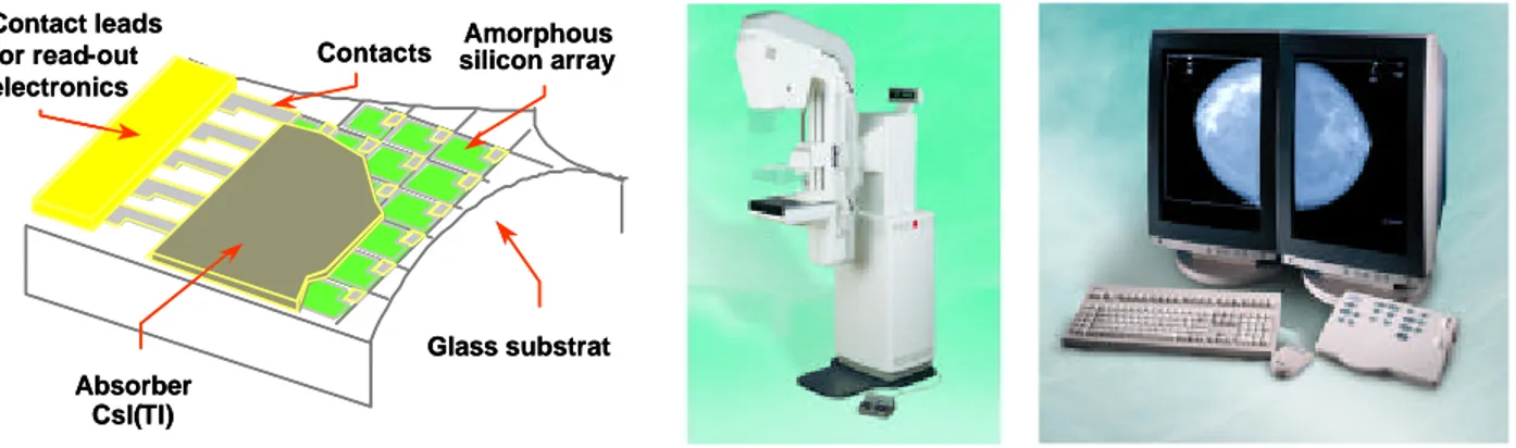
Indirect detection technique
Most current systems for digital mammography are based on X-ray absorbing phosphors coupled to a light photon detector. These systems are indirect in the sense that they convert X-rays to visible light, which is converted into an electric signal, which in turn is digitised. The readout can be accomplished either with a charge-coupled device (CCD) array or photodiodes on a plate of amorphous (i.e. non-crystalline) silicon (aSi). Other solutions include photostimulable phosphors, also known as storage phosphors, with laser readout.
Photostimulable phosphor, BaFX:Eu
Computed radiography (CR) with image plates containing photostimulable phosphors have been available since the beginning of the 1980´s and although not widely used for mammography, CR with
photostimulable phosphors is probably the most frequently used digital system, both for general radiography and mammography. Promising results has been reported in the use of CR with
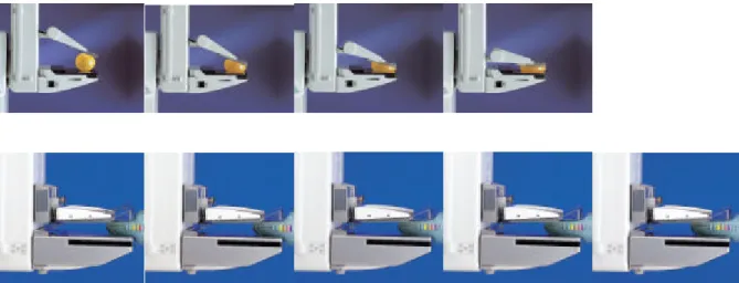
photostimulable phosphors in FFDM [Jarlman et al. 1991, Jouan 1999]. This system features a so-called image plate with a storage phosphor screen, usually barium fluorohalide (BaFX:Eu, where X is a halogen, usually a combination of Br and I), contained in a cassette. The phosphor, also called photostimulable phosphor, contains traps in the form of atomic energy levels of the europium activator, where the ele ctron-hole pairs that are created in response to the X-ray absorption are stored (storage phosphor), and later released when irradiated with red laser light. The resulting blue light is collected by a photo multiplier tube whose output signal is digitised. Erasure of the imaging plate with intense illumination in order to empty the traps is done before it can be used again. The physics of photostimulable phosphors has been reviewed in detail [von Seggern 1998, Yaffe 2000].
Traditionally, these systems were designed for single side reading, but Fuji has developed a system with a new image plate with a transparent support, HR-BD, and a new reader with dual side reading, FCR 5000 MA, adapted for mammography, Figure 6. This has improved both the sensitivity and the spatial
resolution [Arakawa et al. 2000, Saotome 2001]. The pixel size is 50 µm x 50 µm due to a higher sampling frequency than previous high-resolution systems (100 µm x 100 µm). The wavelength of the laser light is 660 nm, the same as before, but a transparent support of the phosphor BaF(Br,I):Eu2+ has made it possible to collect emitted light also from the remote side of the screen with a second photo multiplier tube. This extra light and the higher attenuation of the X-rays due to increased thickness of the phosphor has increased the sensitivity, especially at low spatial frequencies. The phosphor is also
composed of finer grain, which results in a higher sharpness and less structure noise. Image processing, e.g. filter technique can also contribute to the image quality.
The system with dual side reading has a higher DQE than previous systems, which can be used either for improved image quality or a lower dose or both. A disadvantage of all image plate and screen-film
systems is the handling of the cassettes. They have to be put into a reader whose capacity is limited, which may be a problem in high volume screening.
The system is produced and marketed by Fuji, and was commercially available in 2001. Clinical trials are in progress and Fuji expect to get a premarket approval (PMA) from the Food and Drug Administration (FDA) in the USA during 2003 for film reading of laserprinted images from this system. Both formats 18 cm x 24 cm and 24 cm x 30 cm are available. About 25-30 systems were installed in December 2001. Features like peripheral equalisation are incorporated also for hard copy reading on film, and more important, development of a dedicated workstation and CAD are also performed. Clinical tests are in progress in Japan and a workstation will be marketed in 2002 [Lazarz 2002].
Siemens plan to start marketing their first FFDM system with this photostimulable phosphor system produced by Fuji as Siemens Digiscan M in April 2002 and from 2003 also in the USA [Kokk 2002]. Another photostimulable phosphor, CsBr:Eu2+, can be grown with a columnar structure (as CsI(Tl), see below). Since also the absorption is high, image plates with this phosphor have a potential for both higher MTF and DQE than e.g. BaF(Br,I):Eu2+ [Leblans et al. 2001].
Phosphor – charge-coupled device, CsI(Tl)-CCD
The most frequently used digital mammography system to produce images without a cassette is the use of an X-ray absorbing phosphor coupled to a CCD photo-detector [Karellas et al. 1992]. Although it has been made in full-field format, the widespread use has been in the form of small area systems due to technical problems and high costs. A frequently used phosphor is gadoliniumoxisulfid, Gd2O2S, with a thickness of
about 100 µm [Gambaccini et al. 1996], also frequently used as phosphor in screen-film systems. A principle problem with this kind of phosphor is the light spread, which is dependent of the way the light has to travel in the phosphor, and therefore primarily on its thickness. Instead, another kind of X-ray absorber, a thallium-activated caesium iodide, CsI(Tl), scintillator can be used with a thickness of about 100 µm. It can be grown with a columnar structure, which behaves like an optic fibre. These needle -like crystals convey the light with less spread than the phosphors so far used in screen-film and image plate systems, even if it is made thick enough to attenuate most of the X-rays. For high resolution and sensitivity, CsI(Tl) should therefore be used [Evans et al. 2002].
CCDs are usually sensitive to X-rays, but can be manufactured so that the CCD is not damaged by the irradiation [Gambaccini et al. 1996]. Another technical problem with CCDs is that cooling can be needed in order to reduce the noise. Then condensation of water might occur, and the system could be out of order.
Small field of view
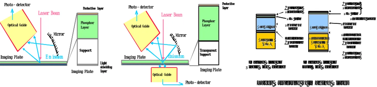
Due to manufacturing difficulties, the size of CCDs is usually limited to about 2.5 cm x 2.5 cm. In a detector with a small field of view, typically 5 cm x 5 cm, the light from the X-ray absorbing phosphor or CsI(Tl) scintillator must be transferred with a demagnification factor of about 2. This can be performed with optical lenses and mirrors or with the use of tapered fibre optic (Figure 7). In both cases the collection efficiency of the light decreases as the demagnification factor increases [Yaffe 2000]. The highest collection efficiency is obtained with fibre optic. Also the spatial resolution can deteriorate when the light is transferred with demagnification.
It is possible to produce large CCDs, which can collect the light without demagnification. In Siemens Opdima (Figure 8) the detector has a 100 µm thick CsI(Tl) scintillator and a 4.9 cm x 8.5 cm active area [Thunberg et al. 1999]. Fibre optic is still used, since the CCD is sensitive to X-rays, but the parallel fibres improve the collection efficiency. The intrinsic pixel size of the detector is 12 µm x 12 µm. In high-resolution mode adjacent pixels are summed to 24 µm x 24 µm pixel size, and in normal mode to 48 µm x 48 µm pixel size.
Mosaic
A so-called mosaic detector, composed of 3 x 4 detectors of CsI(Tl) coupled to the same number of CCDs, each with tapered fibre optic and a demagnification factor of about 2, will have sufficient area for FFDM, Figure 9. One problem is to avoid artefacts due to the intersection between the CCDs, another is the high cost. The company Trex (at that time with mammography divisions Lorad and Bennet) has developed a mosaic detector with an active area of 19 cm x 25 cm and 40 µm x 40 µm pixel size [Cheung et al. 1998]. About 20 systems have been manufactured [Magnusson 2002]. In 2000, Trex was purchased by Hologic, another USA company, and all mammography equipment from these companies are now in the Hologic`s Lorad division. An approvable letter (a preliminary stage to PMA) was received for the mosaic system from FDA in October 2001 after three years of clinical tests. Despite of that it is unlikely that further systems will be manufactured, as Lorad soon expect a PMA for their aSe detector system (see below). Scanning
A digital mammogram can be acquired as a simultaneous full-area image or by a scanning procedure. In the latter case, the X-rays are collimated to a narrow beam that is scanned over the breast and
synchronised with a detector of similar form that measures the transmitted radiation. The procedure effectively reduce scattered radiation without the need for a grid. Thus there is a possibility of substantial improvement of image quality and/or a lower dose, at least for thick and dense breasts.
A disadvantage with scanning systems is that the acquisition time is longer (typically about five seconds compared to less than one second). This result in a heavy heat loading on the X-ray tube, and the system must be operated with sufficient X-ray tube loading capacity for the scanning task. In addition, the breast has to remain compressed for a longer period of time. It is however important to note that the exposure in any point of the image will only be in the order of milliseconds. So, the system is less sensitive to motion in the breast compared to a non-scanning system with the same exposure time.
Fischer has developed a scanning system called SenoScan, Figure 10. Their detector has a row of four CCDs in so-called time delay integration (TDI) mode, each coupled to a CsI(Tl)-scintillator by means of parallel fibre optic [Tesic et al. 1999]. The pixel size is 27 µm x 27 µm, allowing high-resolution mode in a limited area. In normal mode the signals from adjacent pixels are summed to 54 µm x 54 µm pixel size and the field of view is 22 cm x 30 cm. The scanning procedure takes about 5 seconds and the high demand on heat loading capacity is met with a tungsten anode tube. Different filters can be selected, Al, Mo and Rh, as well as different tube potentials. In high-resolution mode the image length and width are halved, but the scan time is the same. The image is acquired with a grey scale of 12 bits (4096 intensity levels), and displayed after about 10 seconds. A so-called acquisition workstation is connected to the mammography unit for a preliminary check of the image. A dedicated so-called review workstation is also available for monitor reading.
After clinical tests in the USA, Fischer SenoScan was the second FFDM system to receive a PMA from FDA in September 2001. It is approved for reading of images on both film and monitor. Since about the same time the system is also marketed in Europe and the first systems are installed during the first quarter of 2002 [Young 2002].
Phosphor – amorphous silicon, CsI(Tl)-aSi
Also in this system a caesium iodide scintillator with needle like crystals is used, resulting in as low light spread as for the CsI(Tl)-CCD systems. One advantage over these systems is that the flat panel detector can be made with large enough area for FFDM.
CsI(Tl) is evaporated directly onto a large active matrix area of thin film transistors (TFTs), each connected to a photodiode of amorphous (hydrogenated) silicon, aSi. These photodiodes convert the optical signals to electrical charge on the storage capacitor of each detector element. Each diode is connected by the TFT switch to a dataline, which is read out and digitised. The TFT and other electronics in each pixel have to occupy a part of the pixel area, thus reducing the portion of the pixel area for the photodiode. That portion constitute the fill factor. If the pixel size is decreased, the fill factor will also decrease, which result in reduced efficiency of the detector.
Besides the fill factor problem, the manufacturing process is not simple and so far only General Electric has developed a commercial mammography system, Senographe 2000D (Figure 11), with a pixel size of 100 µm x 100 µm and an active area of 19 cm x 23 cm [Vedantham et al. 2000, Lewin et al. 2001]. The detector is mounted in a conventional mammography unit with an acquisition workstation connected to it for preliminary check of the image. A dedicated review workstation is also available for monitor reading, Figure 11. The grey scale of the processed image is 12 bits (4096 intensity levels).
The exposure is controlled with an advanced AEC. The anode/filter/tube potential is first selected
automatically with the compressed breast thickness as an input parameter. After a pre-exposure of 4 mAs, the preliminary image is analysed, and anode/filter/tube potential is selected for the main exposure. Also the tube loading (mAs) is selected from an analysis of the image, in which the breast contour is located and then the area behind the densest part of the breast. This seems to be very well functioning, but the user is limited to a preselection of Dose, Standard or Contrast AEC mode (increasing dose level in that order). Unlike conventional mammography units there is no manual AEC, i.e. one can not manually select anode/filter/tube potential and let the system select the mAs for a correct exposure level.
The GE Senographe 2000D received the first PMA for FFDM from the FDA in the USA in January 2000, and after two years about 250 systems are installed in about 20 countries. The PMA was only for film reading of the images, however since November 2000, GE also has a PMA for soft copy reading, the first time FDA has approved reading of mammograms on monitor instead of film.
It is unlikely that other companies than GE will market FFDM systems based on this technique. Siemens announced for instance in November 2000 that they had put an end to their development of CsI(Tl)-aSi for mammography and instead will market the Fuji HR-BD, FCR 5000MA, CR system and an amorphous selenium system.
Direct detection technique
Direct sensors based on amorphous selenium (aSe) are now being developed for digital mammography. The X-rays are converted into an electric signal without the intermediate step via visible light. Thus, spatial resolution is not deteriorated by diffusion of the secondary light, which can be large especially in phosphors like e.g. Gd2O2S and exist to some extent also with columnar CsI(Tl).
Flat panel detector is a common name for both indirect detectors and direct detectors with the interacting media (e.g. Gd2O2S, CsI(Tl) or aSe) close to a large area of TFT or similar readout array. This is
complemented with either a light sensitive substance like aSi (indirect charge collection) or charge collection electrodes (direct charge collection), in both cases also with storage capacitors for the collected charges.
Photoconductor, aSe
The direct detectors are usually based on amorphous selenium, a photoconductor earlier used in the xeromammography systems. When amorphous selenium is hit by X-rays the photons interact with the detector plate and ele ctron-hole pairs are created which can be guided directly to the surfaces of the photoconductor by the applied electrical field, Figure 12. There is very little spreading of the signal due to the strong electric field and measures to reduce charge motion, once they have reached the surface. The readout device may be similar to the one used in the CsI(Tl)-aSi system, but with electrodes instead of photodiodes. Because electric field lines can be bended, the effective fill factor can be much higher than the geometric fill factor (the electrode portion of the pixel area), even close to 100%, and pixel sizes less than 100 µm x 100 µm can be used without a troublesome reduction of the effective fill factor.
The detection efficiency is high because of the high effective fill factor and since the detector can be made thick enough to absorb close to 100% of the incident X-ray photons in mammography, about 200-250 µm is sufficient. In general radiography using higher energies, high efficiency is not always the case and the DQE of aSe detectors is therefore not impressive in all cases. However, in mammography the DQE can be significantly higher than the DQE of earlier mentioned systems due to both a high efficiency and a high MTF resulting in a better relationship between image quality and dose.
Amorphous selenium has several manufacturing advantages reducing the costs. The technique has been under intense development in recent years [Lee et al. 1995, Debrie et al. 2000a and 2000b, Gingold et al. 2000, Rodricks et al. 2000, Lee et al. 2001, Polischuk et al. 2001], and several manufacturers have announced that they will market a FFDM system based on aSe. Clinical trials are in progress in the USA and Europe and Lorad expect to get a PMA from FDA in the USA for their FFDM system Selenia and start marketing during the first half of the year 2002 [Magnusson 2002]. The detector is nominally 25 cm x 30 cm with a pixel size of 70 µm x 70 µm and an aSe layer thickness of 250 µm [Lee et al. 2001]. It is developed by Direct Radiography (now a Hologic company as Lorad, but founded in 1996 as a subsidiary of Sterling Diagnostic Imaging). Siemens will also market this detector, Figure 12, probably in about 2 years [Kokk 2002] as a result of an alliance between Hologic and Siemens announced in November 2001. Clinical tests are also ongoing in Finland since November 2001 with a FFDM system from
Instrumentarium called Delta DX [Ihamäki 2002] with an aSe-detector from Anrad in Canada [Debrie et al. 2000a, Polischuk et al. 2001]. This detector has an aSe-thickness of 200 µm, and a pixel size of 85 µm x 85 µm. The active area is 17.4 cm x 23.9 cm, which is similar to a standard 18 cm x 24 cm screen-film cassette [Polischuk et al. 2001].
The charges from aSe can also be collected by a complimentary metal-oxide semiconductor (CMOS) sensor array. A clinical prototype of a small-field digital mammography detector with an active area of 13.5 cm x 11 cm (2 x 2 sensors, each 6.75 cm x 5.5 cm) and a pixel size of 66 µm x 66 µm has been constructed by Trex [Sexton et al. 2000].
Other photoconductors that are studied as potential candidates in direct detectors for digital
mammography are lead iodide (PbI2) and mercuric iodide (HgI2) [Street et al. 2001, Jee et al. 2001,
Hermon et al. 2001].
Direct photon counting technique
The techniques based on indirect or direct detection of charges involve analogue intermediate steps that introduce electronic noise. However, when the photons are counted directly, the system can be made entirely “quantum limited”, i.e. the noise is determined only by the number of X-ray quanta detected. Another limitation of earlier techniqes is that they are energy integrating, i.e. the signal from a detector based on indirect or direct detection of charges will be proportional to the mean energy absorbed in the detector. The ideal situation would be the opposite, photons with low energy should have higher weight than high energy photons, since the information content of each transmitted photon is higher due to the increased attenuation at lower energies. With photon counting technique this can be achieved, provided the energy of each photon is determined. However, “only” counting the photons can be regarded as the use of a weight factor 1, which is an improvement compared to energy integration.
If the entrance spectrum and the compressed breast thickness is known, analysis of the energy distribution of transmitted photons may lead to new information about the tissue in the breast.
Solid-state detector, Si(B)
This system is not described in the literature as comprehensively as other digital detection techniques for mammography, and will therefore be evaluated in more detail.
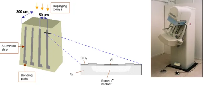
The Sectra Microdose Mammography, MDM, is a full-field digital mammography system with a solid-state de tector, in this case Si(B), using direct photon counting technique in a scanning geometry. The
detector was originally developed by Mats Danielsson and co-workers at the Royal Institute of
Technology, Stockholm [Beuville et al. 1998, Danielsson et al. 2000]. Now the mammography detector is further developed and produced by Mamea Imaging AB, Stockholm, Sweden and marketed by Sectra. A review workstation, developed by Sectra and designed for high volume screening, can be used together with the Sectra MDM unit. Clinical tests are ongoing in Stockholm, Sweden since November 2001, Figure 13. The system is marketed in Europe and the first one will be installed during the second half of 2002. It is expected that clinical trials also will start in 2002 [Danielsson 2001].
Preliminary data indicate the possibility of a substantial dose reduction with an AGD of 0.2-0.3 mGy for a “typical” breast, which is about 1/5 of the AGD of common screen-film systems today [Danielsson 2001]. The main reasons for the low dose are the almost 100% detection of the transmitted X-ray photons (dose reduction with about a factor of 2) and the absence of a Bucky grid due to the scanning technique (contributing with another factor of about 2-3). The system has 99% scatter rejection [Cederström et al. 1999].
A disadvantage of the system is the long scan time of about 5 seconds, which is the usual limitation of a scanning system (as described above in connection to the Fischer SenoScan). The heavy heat loading on the X-ray tube is in this case solved with an X-ray tube having a tungsten anode, an aluminium filter, and a tube potential of 30 kV.
The photon counting in the Sectra MDM FFDM system (Figure 13) occur in a solid-state detector of boron implanted high purity silicon, Si(B), in whic h an electric field is applied between two aluminium electrodes by a potential difference of 100 V. The energy of X-ray photons in mammography, in this case maximum 30 keV, results in an almost 100% interaction efficiency in 10 mm of silicon. The total
attenuation of the incident photons is 96.5% at 30 keV, rapidly increasing towards lower energies [Berger et al. 1987], but the scattering part of this attenuation, coherent and incoherent scattering, is of no use for detection. However, most interactions are by photoelectric effect, 93.3% of the incident 30 keV photons interact in this way [Berger et al. 1987]. Due to the energy distribution of the X-rays, the total
photoelectric attenuation of the incident X-ray spectrum is thus close to 100%. The kinetic energy of the photoelectrons is locally absorbed within 10 µm from the site of interaction (CSDA range, according to ICRU, 1984), by the formation of thousands of electron-hole pairs (e.g. about 7000 from a 25 keV photon, or 3.6 eV per ele ctron-hole pair). The charges are rapidly moved by the electric field and collected on the electrodes within about 10 ns, which results in an electric signal available for analysis. In principle the energy of each interacting photon can be determined, but in the present application only the number of photons above a threshold energy of about 10 keV are counted [Danielsson 2001].
A large number of non-imaging solid-state detectors, made of Si and germanium (Ge), have been
commercially available for decades and used in research, the nuclear industry and medicine. However, as far as we know there has been no marketed medical X-ray imaging application with such a detector operating in a mode when each X-ray photon is detected individually. In order to use this detection principle in X-ray imaging, two main problems had to be solved, i) the formation of an image matrix and ii) the handling of the very high count rates resulting from the high photon fluence rates.
i) The solution of the first problem starts with the formation of a sequence of detectors in a row from a cross-section area of 300 µm by about 10 mm wafer of boron implanted high purity silicon. From this wafer, a large number of detectors, twenty per mm, are created by applying thin aluminium strips (width 25 µm) on one side and an aluminium layer on the other side of the 300 µm thick silicon wafer, Figure 13. Several of these detector rows are put together in a chain to form a joint row at about 24 cm length with each of the segments carefully aligned in the anode-cathode direction to point at the focal spot of the X-ray tube. When the row of detectors is moved in a scanning mode, an image matrix of 24 cm x 26 cm with a pixel size of about 50 µm x 50 µm is created. In order to increase the collecting efficiency for the X-ray photons transmitted through the breast (only a few hundreds per pixel in a collection time of 1 ms behind a normal breast), several parallel rows of detectors are scanned simultaneously [Danielsson 2001].
The pixel size is determined in one dimension by the distance between neighbouring ele ctric fields, 50 µm. These are formed by the potential difference of 100 V between each aluminium strip, forming one
electrode, and the other electrode, which is the aluminium layer on the other side of the silicon wafer that works as a joint electrode. In the other dimension, the 50 µm slit collimator between the focal spot of the X-ray tube and the compression plate determines the pixel size, i.e. only 50 µm of the 300 µm detector width is hit by X-ray photons. Since X-rays transmitted through the breast are counted in a scanning process, the resolution in the scanning direction is determined not only by the width of the slit, but also by the scanning distance (about 50 µm) at each occasion the detector is counting events in a single pixel. ii) The solution of the second main problem, the high count rates from thousands of 300 µm x 50 µm detector elements (resulting in about 50 µm x 50 µm pixels) read out about each millisecond, was found using technology developed for high-energy physics experiments [Haber 2000]. The first condition is that charge collection in the Si(B) detector is very fast, in the order of 10 ns. Then integrated and parallel readout of the detector elements with high-speed parallel-processing Application Specific Integrated Circuits (ASICs) has been developed. Each 300 µm x 50 µm detector element can count up to 0.5 million X-ray photons per second with no more than a few percent loss of data [Danielsson 2001].
A possible further development of this direct photon counting technique is “spectrometry”, i.e. to use the energy information of each X-ray photon detected. The energy is already determined, and each photon above an energy of about 10 keV is counted, but the detailed energy information available is not used. Weighting of the photons using higher weight for low-energy photons will increase the DQE [Cahn et al. 1999].
Another possible development that can lead to both a reduction of the scanning time, and an energy distribution at more optimised energies, is the use of a refractive X-ray lens [Cederström et al. 1999 and 2000]. Then the photons from the X-ray tube has to pass through a lens of e.g. 60 mm length, that in a simple form can be be composed of two pieces from a phonograph LP record. When the photons pass through about 300 LP groves, it works as a refractive lens, changing both the energy and the direction of the X-ray photons. In this way the photon fluence used for the scanning process can be increased and the X-ray spectrum be “tuned” at more optimised energies. More sophisticated lenses can be constructed, and it has already been demonstrated that this technique could have the potential of reducing the scanning time to 40% and the dose to 80% from the present situation for 7 cm thick breasts with preserved image quality. It is however a challenge to build such a system for clinical use [Cederström 2001].
Other direct photon counting techniques
An experimental system [Arfelli et al. 1997] with a similar silicon detector as that in the Sectra MDM system, but with a larger pixel size of 200 µm x 300 µm, has been constructed. The scanning interval is 100 µm. Another experimental system [Mali et al. 2000] has a pixel size of 100 µm x 220 µm and a scanning interval of 25 µm.
A detector filled with krypton (Kr) was originally developed by Tom Francke and co-workers at the Royal Institute of Technology, Stockholm [Francke et al. 2001a and 2001b]. The detector is now developed by the company XCounter in Danderyd, Sweden. Single X-ray photons entering the gas volume through a thin window can be detected and the energy of the photon can be determined. When an X-ray interacts through photoelectric effect in the gas, its energy is locally absorbed. The gas is ionised along the photoelectron track and the released electrons undergo avalanche amplification in the electric field. The result is a fast signal in the anode that can be detected and localised as the anode is segmented. As for the other direct photon counting detector described above, the high count-rates are handled using technology developed for high-energy physics experiments. The technique has a potential to be used in digital
mammography in a scanning mode and such a detector is currently under development. Information on the performance is not available yet.
The development of direct photon counting detectors is a consequence of the dramatic development in microelectronics in recent years. Other techniques are likely to follow. Among solid-state detectors that has been suggested are gallium arsenic (GaAs) for direct photon counting [Bencivelli et al. 1991 and 1994, Amendolia et al. 1997] and cadmium zinc tellurium (CdZnTe) for spectrometry of mammographic X-ray spectra [Miyajima et al. 2001].
Post processing and displaying
An important advantage in digital mammography is the possibility of doing post-acquisition image processing. As mentioned above, one main difference between SFM and DM is that the response curve of the digital system is basically linear contrary to the S-shaped HD curve of SFM. Some conditions, e.g. the use of a particular anode/filter/tube potential combination, can to some extent be “corrected for” with image processing. The slope and the shape of the response curve of a digital system can easily be adjusted resulting in much better low contrast resolution, provided the digitisation was made with sufficiently small increments, and the contrast differences are significant, which is determined by the sensitivity and the noise level of the system.
Different post-acquisition processing techniques can be performed such as adjustments of window level and window width, edge enhancement and magnification. Peripheral equalisation is an example of a more advanced post processing technique, which helps visualise the skin line and nearby subcutaneous
structures.
Film reading
Of course it is possible to print out laser films and perform so-called hard copy reading of digital
mammograms. Until November 2000 it was the only display technique approved by the FDA in the USA. The dela y in development of dedicated workstations has resulted in the use of film reading in many centres using DM, mainly imaging plates. However, to take full advantage of the digital concept, monitor reading must be applied. There are several advantages for that, diagnostic as well as logistic.
Dedicated workstation for monitor reading
During the early years of digital mammography there has been a lack of suitable workstations for so-called soft copy or monitor reading. Actually, the increased amount of information in the digital images present a substantial challenge and is probably the explanation why workstation development has been delayed. High volume screening is becoming more and more prevalent and there is clearly a need to replace the cumbersome handling of film with monitor reading. In many centres about 100 examinations are read in one session of about one hour.
There are three main problems with the present workstations, (1) no specialized work-flow support for screening mammography, (2) insufficient grey scale resolution and (3) insufficient spatial resolution. (1) The greatest challenge is perhaps the workflow, especially in a screening setting. Mammograms from at least 100 women should be possible to handle per hour. Four new images per woman need to be displayed together with four images from a previous investigation. Looking at the conservative situation with 100 µm pixel size and 8 MB per image this would mean 64 MB per case, which implies 6.4 GB per hour if you read 100 cases per hour and almost 10 GB if 150 are read. In a situation with 50 µm pixel size 4 times as many bites need to be handled, which is certainly a problem. A fast workstation with at least 5-10 GB of RAM is needed as well as fast communications with the PACS and RIS systems.
(2) The next problem is the grey scale resolution. The images should be displayed with a grey scale that is near optimal requiring minimal manipulation. Current monitors do not have enough greyscale span to accommodate the data available in a digital mammogram in a single display representation. Of course, this can be solved by the radiologist using different display settings. However, this is time consuming and impractical in a busy routine. Different workstations have different capacities in this respect. The GE review workstation can display 8 bits, which means 256 levels of grey. Other workstations under development can display 10 bits, which means 1024 levels of grey. The eye can perceive only about 150 levels of grey. The problem is then not the number of grey levels presented [van Woudenberg et al. 2001], but to see that they contain the information that is needed for the imaging task. If a 14 bit digital image is compressed to a 10-bit representation, only 1/16 of the full grey scale can be seen in one presentation with full grey scale resolution. With an 8-bit representation, only 1/64 of the full grey scale can be seen
correspondingly. It is therefore necessary to extract the information to be presented very carefully. The solution to this so far, as for the GE review workstation, is the use of several different window levels (three in that case) that can be quickly selected on a special keyboard.