SKI Report 00:18
Evaluation of the Thermal Effect in
a KBS-3 Type Repository
A Literary Survey
Patrick Goblet
Ghislain de Marsily
March 2000
SKI Report 00:18
Evaluation of the Thermal Effect in
a KBS-3 Type Repository
A Literary Survey
Patrick Goblet
1Ghislain de Marsily
21
Centre d’Informatique Géologique
Ecole Nationale Supérieure des Mines de Paris
35 Rue Saint-Honoré
77305 F – Fontainebleau
2
Laboratoire de Géologie Appliquée
Université Pierre & Marie Curie
4 Place Jussieu
75252 F – Paris
March 2000
This report concerns a study which has been conducted for the Swedish Nuclear Power Inspectorate (SKI). The conclusions
Preface
The Swedish Nuclear Fuel and Waste Management Co., SKB, presented in its latest RD&D Programme, 1998, the ongoing scientific work related to thermal effects in a KBS-3 repository. The programme shall in accordance with the Act on Nuclear Activities be reviewed by the Swedish Nuclear Power Inspectorate, SKI.
In preparation for upcoming reviews of RD&D Programmes and licence applications SKI has decided to compile an updated overview of existing thermal studies related to the KBS-3 and similar concepts. Professor Ghislain de Marsily, member of the French Academy of Science and Dr. Patrick Goblet, Ecole des Mines de Paris have performed this literary survey.
The report provides an overview of the existing thermal studies in high-level nuclear waste disposal, based on the available literature assembled during the survey. Although the emphasis is on a granitic repository, some results obtained by experiments or numerical analyses of other rock types (essentially clay or volcanic tuffs) are also given.
A general conclusion from this work is that thermal calculations constitute the straightforward part of the much more general problem of the hydro-thermo-mechanical behaviour of a geological host rock under the influence of a heat-producing repository.
A possible follow up work based on this study is to perform additional thermal calculations using available analytical tools, in order to corroborate the SKB results.
Stockholm, August 30, 2000 Öivind Toverud
Summary
This report provides an overview of the existing thermal studies in high-level nuclear waste disposal, based on the available literature assembled during this survey. Although the emphasis is on a granitic repository, some results obtained by experiments or numerical analyses of other rock types (essentially clay or volcanic tuffs) are also given.
It is well known that high-level nuclear wastes (spent fuel or vitrified reprocessed waste) generate a great amount of heat, whose power decays with time as the radionuclides decay. Because of this heat output, it is generally accepted that waste cannot be placed in a repository immediately after extraction from a reactor but must be stored for some tens of years in a temporary storage unit before disposal. Even after this temporary storage, the residual heat production is expected to produce a raise of temperature in the near as well as the far field. This temperature raise must be evaluated, because it impacts on other aspects of the repository evolution.
Excessive heat loading can generate mechanical failure of the rock, chemical degradation and transformation of the buffer and rock, water vaporisation and condensation. In many countries, a maximum temperature of less than 100°C has been selected, in order to avoid these difficulties. If the repository is backfilled and resaturated, the heat load can generate convective movement of the water and therefore, transport of dissolved elements away from the repository. Given that the heat generated by the wastes decays with time, the maximum temperature at the repository level is generally reached after a few hundred years, but even if the temperature starts to decrease, the total heat loading of the rock formation continues to increase, until the temperature front reaches the upper boundary of the system (the rock surface) and releases the heat into the atmosphere. The total heat load of the host rock typically starts to decrease only after about 10,000 years. The mechanical effects can therefore peak long after the maximum temperature has been reached. The surface deformation of the rock by expansion (on the order of 1 m above a repository) is often reached at such large times.
Another thermal problem examined in some repository studies is the effect of climate variations at the surface. A glaciation scenario, for instance, would decrease the temperature at the surface, perhaps generate permafrost deep in the ground, that could potentially interact with the thermal pulse from the repository.
The maximum heat loading in a repository is an important design parameter when the extent of a repository is determined, given the amount of waste and the age at which this waste must be disposed. To determine this heat loading, it is necessary to define either the maximum acceptable temperature at the buffer-rock contact, and/or at the outer boundary of the canister. Design options include the nature and dimension of the buffer zone, its water saturation (in the case of clay) and the distance between canisters.
The temperature distribution in the host rock, in the buffer and inside the waste package can be determined by thermal calculations, if the density of waste in the repository is known, as well as the geometry of the disposal option, the properties of the buffer and the host rock and potential gaps between the canister and the rock. These calculations can be made with different degrees of sophistication, e.g. in 1, 2 or 3 dimensions, and with constant or variable material properties (variable water saturation of the medium, thermal properties varying with temperature, etc). The heat transfer is generally assumed to occur mostly by conduction, but in some cases, vaporisation and condensation of water with a large “heat pipe” effect must also be considered. In simple cases, analytical solutions can be used, but generally, numerical techniques are preferred, in particular when other processes are coupled with the temperature in the model : mechanical effects, geochemical effects, hydrological effects.
In this review, the source of information is mostly “grey literature”, i.e. technical reports. In order to thoroughly cover such reports, the following organisations and countries were contacted :
-SKB, SKI, Sweden; -POSIVA, Finland; -CEA, ANDRA, France; -DOE and NRC, US
-AECL and Ontario Hydro, Canada; -NAGRA, Switzerland;
-ENRESA, Spain
-CEN-SCK and ONDRAF, Belgium -QUANTISCI, England (and Japan) -NEA/OECD
-CEC - DGXII, Brussels.
A general conclusion from this work is that thermal calculations constitute the “easy” part of the much more general problem of the hydro-thermo-mechanical behaviour of a geological host rock under the influence of a heat-producing repository.
We have examined contributions from various countries, whose repository concepts are quite similar in principle, but different in their details: containers may be stacked in boreholes, lined up horizontally in drifts, or buried in a buffer material in rooms. This does not greatly modify the general modelling approach.
It is clear that at their present stage of development, models are not able to simultaneously cover all the scales, from the regional to the near-field: choices must be made as to what scale is appropriate for a particular aspect. Generally, a very detailed model must be restricted to a local region, which is either a sub-domain of a more general model, with boundary conditions extracted from this regional model, or bounded on the basis of symmetry considerations. In any case, the vertical extent of this local model must be sufficient to include realistic boundary conditions. In a regional
may have advantages, because one is forced to correctly assess the orders of magnitude of various mechanisms to make the appropriate approximations.
The Equivalent Continuous Medium approach is well suited to the modelling of heat transfer, because this phenomenon is rather insensitive to the presence of fractures. Fractures must, however, be taken into account when the effect of heat on water trajectories is assessed. Generally, the density coupling for sparsely-fractured rocks is a one-way coupling: heat transfer is insensitive to the flow in fractures, but the flow in fractures can be modified by the temperature long after the thermal perturbation of the medium has vanished.
Various numerical techniques are available to solve the heat transfer equation: Finite Elements, Finite Differences, Distinct Elements or even analytical techniques. These techniques have different abilities to deal with coupled mechanisms, but perform equally well for the heat diffusion equation. Thus, the results do not seem to depend greatly on the modelling techniques, because the heat conduction equation is rather robust and not prone to unstable solutions.
There seems to be little uncertainty regarding the value of thermal parameters (thermal conductivity and specific heat of the various materials), and as a consequence, little uncertainty regarding the results of thermal calculations in terms of temperature. This is especially true for saturated media. The major source of uncertainty in the predictions seems to be the behaviour of the bentonite, with respect to its water content : the saturation of the bentonite strongly affects its thermal conductivity, and furthermore, if the bentonite is only partly saturated, two-phase transport of water and heat can occur, making the modelling and predictions much more complex. More precisely, the variation in water content is difficult to predict with accuracy, which impacts on the thermal calculations. The possible existence of a scale effect has been proposed to explain discrepancies between field measurements and predictions based on parameters measured in the laboratory. However, this scale effect has, so far, not been demonstrated for thermal parameters, as is the case e.g., for the hydraulic conductivity.
The most elaborate modelling work found during this review seems to have taken place in Sweden: the concepts used in the various modelling exercises examined here are consistent, except for minor differences in parameters, and reflect the increasing power of numerical tools.
A large body of experimental evidence has been and still is being developed around the hydro-thermo-mechanical aspects. These experiments cover a variety of spatial and temporal scales. The modelling results obtained in connection with these experiments are generally in good agreement with the observations as far as temperature is concerned. At present, the most elaborate work (excluding the US programmes which concern a different hydrological situation) seems to be the FEBEX experiment, on the behaviour of the bentonite buffer.
Contents 1. Introduction ... 1 2. Aspects to be addressed ... 3 2.1. Modelling... 3 2.2. Modelling approaches... 4 2.3. Numerical technique ... 4 2.4. Scale... 4 2.5. Mechanisms... 4 2.6. Parameter values ... 5
3. Mechanisms of heat propagation... 5
3.1. Mechanisms... 5
3.2. Boundary conditions... 7
3.3. Parameters ... 7
3.4. Couplings... 8
3.5. Conclusion... 9
4. Comparison of various modelling approaches ... 9
4.1. Sweden ... 9
4.2. Switzerland ... 14
4.2.1. Analysis of Hopkirk and Wagner (ref. [68])... 14
4.2.2. Heater test report (ref.[117])... 15
4.2.3. Kristallin-I report (ref[95])... 18
4.2.4. Sato et al. (ref.[114]) ... 19
4.3. Canada ... 22
4.3.1. Generic thermal modelling (Tsui et al., ref. [129],[130])... 22
4.3.2. Thermal modelling of the Whiteshell area... 26
4.4. United Kingdom... 28
4.5. France ... 30
4.5.1. CCE “Thermal-loading” study... 30
4.5.2. « Vie d’un Site » - “ Life of a site ” - study... 31
4.5.3. PAGIS study ... 32
5. Modelling issues...34
5.1. Thermoconvection ... 34
5.2. Dimensionality ... 35
5.3. Non linear phenomena... 36
5.4. Source description... 36
6. Experimental support for parameter evaluation...37
6.1. Börgesson et al. (1994, SKB TR 94-29) ... 37
6.2. Stripa... 37
6.3. Fanay-Augères ... 38
6.4. Grimsel: Swiss heating experiment... 39
6.6.2. Description of the mock-up test... 41
6.6.3. Laboratory measurements... 41
6.6.4. Lessons from the preliminary modelling... 41
6.7. Big Ben experiment... 41
6.8. Research Programmes in the HADES lab ... 42
6.9. U.S. experiments ... 43
7. International Projects (DECOVALEX) ...44
7.1. DECOVALEX I ... 44
7.1.1. Benchmark BMT 1: far-field situation ... 45
7.1.2. Benchmark BMT 2: Near-field model with fractures... 45
7.1.3. Benchmark BMT 3: Near-field model with a realistic fracture network ... 46
7.1.4. Test Case TC 2: Fanay-Augères heating experiment... 46
7.1.5. Test Case TC 3: Big-Ben heating experiment ... 47
7.1.6. Lessons learned from DECOVALEX I... 47
7.2. DECOVALEX II... 48
7.2.1. Kamaishi Mine experiment ... 49
8. Climate events...50
9. Conclusions ...53
1. Introduction
This report provides an overview of the existing thermal studies in high-level nuclear waste disposal, based on the available literature assembled during this survey. Although the emphasis is on a granitic repository, some results obtained by experiments or numerical analyses of other rock types (essentially clay or volcanic tuffs) are also given.
It is well known that high-level nuclear wastes (spent fuel or vitrified reprocessed waste) generate a great amount of heat, whose power decays with time as the radionuclides decay. Because of this heat output, it is generally accepted that waste cannot be placed in a repository immediately after extraction from a reactor but must be stored for some tens of years in a temporary storage unit before disposal. In Sweden, this temporary storage is done in CLAB, a wet storage unit of pools built near Oskarshamn, about 30 m below ground.
The initial heat output of the waste is a function of the burn-up, and also of the fuel type. If MOX (Plutonium and Uranium Oxides) fuel is used, for instance, instead of Uranium Oxides, the heat output is much higher, and the rate of decay is much slower (as will be shown below).
The temperature distribution in the host rock, in the buffer and inside the waste package can be determined by thermal calculations, if the density of waste in the repository is known, as well as the geometry of the disposal option, the properties of the buffer and the host rock and potential gaps between the canister and the rock. These calculations can be made with different degrees of sophistication, e.g. in 1, 2 or 3 dimensions, and with constant or variable material properties (variable water saturation of the medium, thermal properties varying with temperature, etc). The heat transfer is generally assumed to occur mostly by conduction, but in some cases, vaporisation and condensation of water with a large “heat pipe” effect must also be considered. In simple cases, analytical solutions can be used, but generally, numerical techniques are preferred, in particular when other processes are coupled with the temperature in the model : mechanical effects, geochemical effects, hydrological effects.
The maximum heat loading in a repository is an important design parameter when the extent of a repository is determined, given the amount of waste and the age at which this waste must be disposed. In a few cases, “excessive” heat loading has been suggested; this requires that the repository be kept open and ventilated for a significant period of time, to extract the heat, until conduction becomes sufficient to distribute the heat in the host rock. To determine this heat loading, it is necessary to define either the maximum acceptable temperature at the buffer-rock contact, and/or at the outer boundary of the canister. Design options include the nature and dimension of the buffer
Excessive heat loading can generate mechanical failure of the rock, chemical degradation and transformation of the buffer and rock, water vaporisation and condensation. In many countries, a maximum temperature of less than 100°C has been selected, in order to avoid these difficulties. If the repository is backfilled and resaturated, the heat load can generate convective movement of the water and therefore, transport of dissolved elements away from the repository. Given that the heat generated by the wastes decays with time, the maximum temperature at the repository level is generally reached after a few hundred years, but even if the temperature starts to decrease, the total heat loading of the rock formation continues to increase, until the temperature front reaches the upper boundary of the system (the rock surface) and releases the heat into the atmosphere. The total heat load of the host rock typically starts to decrease only after about 10,000 years. The mechanical effects can therefore peak long after the maximum temperature has been reached. The surface deformation of the rock by expansion (on the order of 1 m above a repository) is often reached at such large times.
One additional mechanism, which is linked to the thermal regime of the repository, is the coupled effect of the thermal gradient on the transport of water (thermal osmosis) and solute (thermal diffusion). Some work has been done to quantify these “non diagonal effects” in the literature, based on the theory of irreversible thermodynamic processes.
Another thermal problem examined in some repository studies is the effect of climate variations at the surface. A glaciation scenario, for instance, would decrease the temperature at the surface, perhaps generate permafrost deep in the ground, that could potentially interact with the thermal pulse from the repository.
In this review, the source of information is mostly “grey literature”, i.e. technical reports. In order to thoroughly cover such reports, the following organisations and countries were contacted :
-SKB, SKI, Sweden; -POSIVA, Finland; -CEA, ANDRA, France; -DOE and NRC, US
-AECL and Ontario Hydro, Canada; -NAGRA, Switzerland;
-ENRESA, Spain
-CEN-SCK and ONDRAF, Belgium -QUANTISCI, England (and Japan) -NEA/OECD
-CEC - DGXII, Brussels.
2. Aspects to be addressed
In earlier Swedish Performance Assessments (KBS-3, SKB 91, Project 90), all temperature modelling work was based on the thermal analysis of a KBS-3-type repository carried out by Tarandi (1983) [121] and the data presented in his report. In April 1997 the Swedish Nuclear Power Inspectorate completed the SITE-94 performance assessment project. The overall rationale for carrying out SITE-94 was that it should assist SKI in preparing for the licensing of a repository for spent nuclear fuel by building up the necessary review capacity and supporting knowledge.
In SITE-94, different repository-induced temperatures were analysed in order to study the far-field rock-mechanical responses to repository heating followed by the mechanical loading by an ice sheet in the Central Scenario. In the near field, estimates of the decay of heat and temperatures were taken into account when considering both the geomechanical evolution of the rock and the geochemical evolution of the system. The repository temperatures, estimated in each of these studies, vary somewhat according to the type of model, the assumptions and the intended end-use of the calculated temperature values. In these studies, the heat generated by the wastes is modelled with a source term that decays with time.
Future temperature modelling work should strive to use a consistent approach when considering geomechanical and geochemical impacts in both the near and the far field: mechanisms considered, parameter values, numerical techniques, etc.
The objective of this report is to compile and evaluate the current (national and international) knowledge of heat propagation and its impact on repository performance. In this section, we discuss the various viewpoints from which we have analysed the available literature.
2.1. Modelling
Modelling of the thermal behaviour of a repository and its different components is the focus of this study. Modelling approaches are used in various contexts:
§ Generic studies, providing a general analysis of the important mechanisms and giving orders of magnitude of thermal effects. Several international cooperation programmes have served this purpose in recent years (PAGIS programme (ref. [23]), DECOVALEX I (ref. [83]) and II (ref. [84]), etc.).
§ Modelling in relation to an experimental programme : these studies generally have a more restricted focus, but allow models to be directly compared with reality.
§ Site-specific modelling : this type of study tries to represent as accurately as possible the conditions of a real repository.
2.2. Modelling approaches
Fractured media are modelled according to three main approaches:
• Equivalent continuous medium: the porosity and hydraulic conductivity structure related to fractures is not described in detail, but approached through parameters averaged on an Elementary Representative Volume.
• Discrete fracture networks: the fractures are explicitly represented, generally by simple geometric shapes (planar discs or rectangles), sometimes in more detail, through a discretized formulation. It is generally implicit that fractures play the dominant role in water circulation; hence, the permeability of non fractured blocks is considered negligible.
• Distinct Element Approach: the solid blocks are explicitly represented, and the role of fractures is to transmit mechanical constraints between blocks. This approach is specifically oriented towards the description of the mechanical behaviour of a rock mass.
All three approaches have been used in the references that we have consulted. We shall try to determine the implications of the choice of method for the modelling results. The dimensionality of the models is also discussed.
2.3. Numerical technique
The numerical tools are described. Here again, the goal is to examine how the use of a particular model impacts on the results.
2.4. Scale
The spatial scale of available studies ranges from the very local (laboratory experiments on rock or buffer samples) to the regional scale (global site model). Much work is being done on the near field (effect of bentonite saturation, etc).
The temporal scale covers “short-term” (core experiments), “local-time scale” (thermal phase limited to a few thousand years) and “global-time scale” (climate cycles).
2.5. Mechanisms
Studies are available concerning the various components of the confinement system: source term (heat propagation in the container system and resulting thermal output), buffer behaviour (effect of heat on clay properties, moisture distribution) and rock mass behaviour (conductive heat transfer, convection, radiation, mechanical effects).
2.6. Parameter values
Thermal parameters are reviewed, with particular emphasis on the following aspects: origin of values, variability, uncertainty.
Parameter acquisition methods are also discussed; when possible, the various techniques used to measure parameters are compared.
3. Mechanisms of heat propagation
In this section, the main mechanisms of heat propagation in geologic media are briefly reviewed in order to provide a general framework. The presentation is essentially inspired by ref. [15]. This book, which deals with many important issues related to thermal mechanisms in waste disposal, is in French. We will therefore give a short overview of its contents:
• Thermal mechanisms in geotechnics (P.Berest)
• Basics of thermomechanics (P.Berest, G.Vouille)
• Heat propagation in the soil and geothermal flux (G.Vasseur)
• Modelling of thermal and hydraulic fluxes in natural media. Practical considerations (G.de Marsily)
• Modelling of structures under thermal constraints (S.M.Tijani)
• Thermomechanical aspects related to geological disposal of nuclear waste (B.Come, S.Derlich, D.de Bruyn, T.Hueckel, G.Staupendahl, J.P.Charpentier, M.Ghoreychi)
• Finite-Element modelling of structures under thermal constraints. Application to geological disposal of radioactive waste (P.Jamet, A.Millard)
• Rock and soil behaviour at low temperature (D.Blanchard, M.Fremond, M.Levy)
• Calculation techniques used for soil freezing (P.Gonze)
• Recent data on rock behaviour with temperature (R.Houpeurt, F.Homand-Etienne)
• Brittle-fracture mechanics under thermomechanical constraints (P.Jouanna, G.Berthomieu)
3.1. Mechanisms
The description of heat propagation in an immobile medium is based on an experimental law (Fourier’s law) and a conservation equation.
The Fourier law relates the heat flux ϕc across a unit surface to the temperature gradient
θ
ϕc =−Λgrad (1)
ϕc is the conductive flux (W/m 2
), θ the temperature (oC), and Λ the thermal conductivity of the medium (W/moC).
The heat conservation law is:
0 div = ∂ ∂ + t C c θ ρ ϕ (2)
ρ is the medium density (kg/m3), and C the specific heat capacity (J/kgoC). t is time. In a composite medium, such as a porous medium containing water, one must use average thermal properties that combine the properties of each component. The rules for this combination are not always straightforward. Generally, a volumetric weighting (through porosity) is used:
r w
t = Λ + − Λ
Λ ω (1 ω) (3)
Λt is the total conductivity, Λw and Λr the conductivities of water and solid rock. ω is the
total porosity. Likewise:
r w
t C C
C) ( ) (1 )( )
(ρ =ω ρ + −ω ρ (4)
When the interstitial water is mobile, a second heat transfer mechanism sets in: heat is advected with the water. This leads to a modified equation:
0 ) div( = ∂ ∂ + + t C a c θ ρ ϕ ϕ (5)
ϕa is the advective flux (W/m 2
), expressed as
θ ρ
ϕa =( C)eUD (6)
UD is the Darcy velocity.
Finally, a third mechanism of heat propagation is the dispersive flux. Dispersion is due to the fluctuations of the local Darcy velocity around the average value defined by UD.
The dispersive flux is classically expressed by a Fourier-type law:
θ
ϕd =−Λdgrad (7)
Where Λd is an apparent conductivity, expressed in tensor form as a function of the Darcy velocity:
D d =αU
Λ (8)
α is the dispersivity tensor (m), which may have different components in the direction
of velocity and in the transverse directions. It is generally admitted that, for the low velocities considered in the present work, the dispersive flux is negligible compared to the conductive flux.
Introducing the dispersive flux into the conservation equation leads to:
0 ) div( = ∂ ∂ + + + t C d a c θ ρ ϕ ϕ ϕ (9)
Or, replacing each flux by its expression:
(
)
{
t C w UD C wUD}
C ∂t ∂ = − + Λ (ρ ) α gradθ (ρ ) θ ρ θ div (10)3.2. Boundary conditions
Equation (10) may be solved provided that the initial and boundary conditions are appropriate. The initial state is defined by a temperature distribution in the region of interest. Boundary conditions are generally expressed as:
• Prescribed temperature: this occurs when a domain is in contact with a continuously flowing or mixing fluid, such as the atmosphere or a large fluid body
• Prescribed heat flux: this condition describes, for instance, the geothermal flux or the heat flux generated by the waste containers
• Radiation: this condition describes a heat transmission through a thin fluid boundary layer.
Note that the appropriate boundary condition for a given problem may depend on the scale of analysis: for example, the heat-flux condition is sufficient to describe the influence of the thermal load on the surrounding rock, but a detailed description of the temperature distribution near the canister may require a simultaneous solution of the heat transfer equation in the canister and the surrounding media. Likewise, the detailed description of the heat load history may be useless for predictions on the scale of several thousand years, because at this scale the source term appears instantaneous.
3.3. Parameters
A range of variation for the thermal parameters (conductivity and specific capacity) is proposed in ref. [15]. For granite, the range is 1.2 to 4 W/moC for the conductivity, 0.5 to 1 kJ/kgoC for the specific heat. This is a very narrow range compared to those of other parameters such as hydraulic conductivity.
The conductivity of a composite material may be computed with simple formulae when the materials are combined according to a simple geometry: for instance, for two layers of different materials piled up in the direction of the thermal gradient, the equivalent conductivity is the harmonic mean of the individual conductivities. If the thermal gradient is parallel to the layers, the equivalent conductivity is the arithmetic mean. This type of averaging approach is proposed e.g., in [6] and [126].
This might lead to an important variation of granite conductivity when open, dry fractures are present, because air has a much lower conductivity. This is rare in natural conditions, because the mechanical stress prevents the fractures from opening.
The thermal parameters show little variation either with temperature or with pressure. The main sources of variations are the water content (for argillaceous materials) and the appearance of open fractures.
3.4. Couplings
Thermal transfer may, to some extent, depend on hydraulic and mechanical mechanisms: the water flow is modified by temperature because of density and viscosity variations of the water. This, in turn, may modify the advective temperature flux. Similarly, mechanical effects caused by the temperature may modify the thermal parameters. This thermo-hydro-mechanical coupling is a complex problem. However, it becomes very much simpler when one is only concerned with temperature, because:
• The advective heat flux is generally negligible compared to the conductive flux.
• The variation of thermal parameters is negligible.
For these reasons, temperature propagation appears as a quasi-independent mechanism, which can be modelled separately.
Let us finally mention “non diagonal” couplings, discussed by Marsily in [15]: heat flow due to a hydraulic gradient (thermal filtration), an electric-potential gradient (electrophoresis) or a concentration gradient (Dufour effect). These effects are, at present, thought to contribute negligibly to the heat transfer. Inverse effects, such as the Soret effect, coupled with buoyancy effects, might contribute significantly to the solute transfer. This is discussed in, for example, [77] and [44].
In a recent study (ref. [123]), the coupled effects of the thermal loading of a clay-marl repository was analysed by a simplified modelling of the coupled heat, fluid flow, and solute transport. The author assumes that the peak of the thermal output is passed at, for instance, 1,000 years. He reviews the available coupling coefficients in the literature, and concludes that very few measured parameters are available, and that only scoping calculations can be made at this stage. He suggests that the major coupled mechanism is thermal osmosis (water movement in the thermal field towards the heat source). He also considers thermal diffusion, hyperfiltration and chemical osmosis. His modelling results indicate that the thermal osmosis effect is, however, counter-balanced by the geometry of the system : when water flows towards the heat source because of the thermal gradient, the hydraulic pressure increases at the heat source, and the hydraulic gradient counter-acts the thermal gradient, resulting in a zero increase of velocity. He concludes that coupled processes, at least after the thermal peak, are not very important in a performance assessment. However, this calculation was done under the assumption of a homogeneous medium, and it is also shown that if e.g., a fracture makes the medium heterogeneous, the two gradients may not, in some cases, work against each other (water could flow towards the heat source in the unfractured medium and away form the heat source by the hydraulic gradient in the fracture, with a non-negligible net effect). Similar conclusions were reached at Yucca Mountain ([7], [63])
It must be pointed out, however, that most of these studies on coupled properties rely on the Onsager principle of irreversible thermodynamics, which specifically assumes that there is no electrical fields in the medium. Since there are always in natural media, and even more so if pieces of metal are introduced into the medium (e.g. a metal canister), spontaneous electrical potentials which can easily be measured, the theory is
not directly applicable and cannot be used straightforwardly. Additional theoretical work may be required here.
3.5. Conclusion
Let us end this short review of thermal mechanisms in geologic media by two quotations from ref. [15]:
In almost all cases, thermal calculations give results in very good agreement with observations. This is sufficiently rare in geotechnics to deserve being underlined (P.Berest)
Finally, one must note that there is generally excellent agreement between calculations and measurements concerning heat propagation in geologic media (B.Come)
These observations, which are confirmed by our review, are a key result of this work: the modelling of possible temperature evolution around a repository seems to be much more robust and reliable than other aspects (e.g., prediction of water velocity, mechanical behaviour of a rock mass, general THM coupling).
4. Comparison of various modelling
approaches
4.1. Sweden
It may be useful to try to put in historical order the various referenced documents concerning the Swedish approach to thermal problems.
Tarandi (1983, SKB TR 83-22)
Tarandi’s work ([127]) is the basic reference for thermal modelling related to a repository. The modelled geometry is as follows :
• depth of the repository : 500 m
• repository composed of tunnels with variable spacing (25-60 m), inside which boreholes with an average spacing of 6 m (variation 4.3 to 8 m) contain the 4.7 m high canisters. A one-layer and a two-layer design, the latter with a spacing of 100 to 250 m between planes, are considered.
Thermal loading obeys a piecewise-exponential variation with time. The initial loading per canister is 850 W.
The heat transfer mechanism is pure conduction. A zero initial temperature is assumed everywhere, which implies that a temperature increase, and not an absolute temperature, is computed. Due to the relatively limited computing resources available at the time of the study, a simplified approach was devised : a global one-dimensional model (from ground level down to a depth of 4000 m) is used to describe the temperature profile along a vertical axis through the repository centre. A finer local model describes a two-dimensional, vertical cross-section through a gallery (scale 15 x 20 m). Boundary conditions for this model are extracted from the global model. Finally, a steady-state analytical temperature distribution is computed for a single canister. A three-dimensional model is proposed as well. The numerical codes are based on Finite Differences.
The thermal conductivity of the host rock is constant and at 3 W/m/oC, with two variants : 2 W/m/oC and 3.6 W/m/oC. The thermal conductivity of bentonite is assumed to vary with water content in a simple manner : 0.75 W/m/oC for the first 150 years (dry conditions), and 1.5 W/m/oC afterwards (saturated conditions). The specific heat of the rock varies between 1.8 and 2.5 MJ/m3/ oC (average value 2 MJ/m3/oC), and is 2.2 MJ/m3
o
C for bentonite.
Thunvik & Braester (1991, SKB TR 91-61)
This work ([128]) deals basically with the same topic as Tarandi’s (1983), but with some differences regarding parameters and modelling approaches. The basic geometry is the same : KBS-3-type repository, depth of 500 m, single-layer design, tunnel spacing 20 - 30 m, borehole spacing 3 – 6.2 m. The initial heat load per canister is 1066 W instead of 850 W, in accordance with the SKB-91 specifications. Its subsequent evolution follows the same type of piecewise-exponential law.
Taking advantage of increased computational capacity, the geometrical description is fully 3-dimensional. The modelled zone extends from the surface down to 1000 m below the repository and, owing to symmetry considerations, it is restricted horizontally to an elementary zone in the vicinity of a single canister, bounded by three vertical symmetry planes: two that cross the longitudinal symmetry axis of the canister, the third one midway between two boreholes.
The near-field description includes the canister, represented as a homogeneous volume with average material properties, the bentonite buffer around the canister, the backfilling and the host rock.
The heat transfer mechanism is conduction. An initial temperature field is imposed, according to a vertical gradient of 13 oC/km, with a surface temperature of 5.8
o
W/m/oC for bentonite (corresponding to dry conditions). The specific heat of the rock is 2.2 MJ/m3 oC, 3 MJ/m3 oC for backfill and 2.2 MJ/m3 oC for bentonite.
The calculation method is based on a Finite-Element solution of the heat conduction equation.
On the whole, this work is consistent with Tarandi’s work, but makes use of a more recent canister specification and of a higher computing capacity. The conclusions of this work form the basis for thermal calculations in Project 90 ([120]).
Hökmark (1996, SKB AR D-96-014)
This work ([67]) is a local-scale analysis of a subregion of the repository including a tunnel length of 54 m and 6 deposition holes. The thermomechanical modelling uses the Distinct Element technique. The thermal part of the analysis is based on a semi-analytical approach, whereby the heat sources are represented by a superposition of point sources. The underlying hypotheses are : homogeneous medium (the influence of the canister and the buffer is neglected), depth 450 m, tunnel spacing 25 m, borehole spacing 6 m. The thermal loading varies with time according to a law which is close, but not similar, to the law used in Tarandi (1983) and Thunvik & Braester (1991). The initial load is 1050 W / canister. The total number of canisters is 5285. The thermal parameters are similar to those used by Thunvik & Braester (1991) : 3 W/m/oC for the conductivity, and 2.1 MJ/m3 oC for the specific heat.
Hansson et al. (1995, SKI 95 :40 and SKI 95 :41) and Shen et al. (1996, SKI 96 :17 and SKI 96 :18)
This series of reports ([61],[62],[118],[119]) deals with the more general aspect of the effect of thermal loading on the rock stability. However, part of the work is devoted to the calculation of temperature variations. This work is a part of the SITE-94 project. The geometry of the repository is classical (depth 500 m, tunnel spacing 25 m, borehole spacing 6 m). The heat-loading variation follows the formula proposed by Thunvik & Braester (1991) for the first 1,000 years and subsequently, follows a new exponential expression. The initial load is 1,066 W per canister. The total number of canisters is 400 (SITE-94 concept) and 4,000.
The properties of the canister and buffer are not taken into account. The thermal material properties of the rock are 3 W/m/oC (conductivity) and 2 MJ/m3 oC (specific heat).
The initial temperature profile is described by a surface temperature of 6 oC and a vertical gradient of 16 oC/km, resulting in 14 oC at repository level.
The mechanical calculations use the Distinct-Element technique. However, the thermal calculations are based on a semi-analytical approach : point sources are superimposed to describe the spatial extent of the source and its temporal variation.
While computed or measured temperature profiles are generally very smooth, the temperature profiles shown in this study have a jagged shape, whose origin is not clear to us, since the material is supposed to be homogeneous.
Claesson and Probert (1996, SKB TR 96-12) and Probert and Claesson (1997, SKB TR 97-27)
These two authors ([29],[103]) suggest that the temperature field be calculated with an analytical formulation rather than a numerical technique. The analytical formulation is developed in the first reference. It is based on pure thermal conduction. To allow an analytical solution, the medium has to be considered homogeneous. No distinction is therefore made between the thermal properties of the canister, the backfill and the host rock.
In the second report, the approach is applied to a KBS-3 concept. The geometry is consistent with previous work : depth 500 m, distance between tunnels 25 m, distance between boreholes 6 m. The initial thermal load for a single canister is 1,000 W. The subsequent variation with time is consistent with Thunvik and Braester (1991) for the first 1,000 years. A slightly different formulation is proposed after 1,000 years, also formally different from Hansson et al. (1995), but consistent in shape. Finally, the thermal conductivity of the rock is 3 W/m/oC, and the specific heat is 2.2 MJ/m3 oC, in accordance with the value used by Thunvik and Braester (1991).
Israelsson et al. (1997, SKB PR D-97-10)
Thermal calculations are only a part of this report ([75]), devoted to a more general thermo-mechanical approach (discussed also in [60]). The calculations take into account thermal conduction in a homogeneous medium (no distinction between host rock and man-made material). Several geometrical arrangements are considered : one, two or three layers of tunnels, with various vertical distances between layers. In the basic one-layer set-up , the distance between tunnels is in the high range (40 m), while the distance between boreholes is 6 m . Thermal parameters for the host rock are within the usual range : 3 W/m/oC for conduction and 2 MJ/m3 oC for specific heat.
The initial thermal load per canister is significantly higher than in previous studies (2400 W). The reason for this choice is not clear, but could result from an assumption of early disposal.
Ageskog and Jansson (1998, SKB HRL-98-20)
This study ([1]) differs in focus from the previous ones, since it deals with the a priori modelling of an experimental program. It has, therefore, a more limited spatial and temporal scale (5 to 10 years). The geometry is much more detailed than in the studies described above : canister, buffer, backfill and rock are described in detail. The effect of 1 cm gaps between e.g., canister and buffer or buffer and rock can be modelled, which requires an extremely fine Finite-Element discretization.
The basic mechanisms are similar to those of the previous studies. The thermal conductivity of the rock is lower (2.43 W/m/oC) and varies with temperature (2.22 W/m/oC at 100 oC). The thermal conductivity of bentonite also varies with temperature. The thermal load varies with time according to the law used in Thunvik and Braester (1991), but with a higher initial value (1800 W / canister).
Parameter Value reference
Thermal conductivity of granite 3 W/m/oC (2 – 3.6) [127]
Thermal conductivity of bentonite 0.75 W/m/oC [127] (dry conditions)
Thermal conductivity of bentonite 1.5 W/m/oC [127] (saturated conditions)
Thermal conductivity of granite 3 W/m/oC [128]REFMERGEFORMA
T
Thermal conductivity of backfill 2.4 W/m/oC [128]REFMERGEFORMA
T
Thermal conductivity of bentonite 0.75 W/m/oC [128] (dry conditions)REF
Thermal conductivity of granite 3 W/m/oC [67]
Thermal conductivity of granite 3 W/m/oC [61],[62],[118],[119]
Thermal conductivity of granite 3 W/m/oC [29],[102]
Thermal conductivity of granite 3 W/m/oC [75]
Thermal conductivity of granite 2.43 W/m/oC (2.22 at 100 oC) [1]
Specific heat of granite 2,2 MJ/m3/oC [128]
Specific heat of backfill 3 MJ/m3/oC [128]
Specific heat of bentonite 2,2 MJ/m3/oC [128]
Specific heat of granite 2,1 MJ/m3/oC [67]
Specific heat of granite 2 MJ/m3/oC [61],[62],[118],[119]
Specific heat of granite 2,2 MJ/m3/oC [29],[102]
Table 1: Parameter values used in the Swedish studies (values in parentheses indicate ranges of variation)
4.2. Switzerland
4.2.1.
Analysis of Hopkirk and Wagner (ref. [68])
The work presented in this report is a part of the Projekt Gewähr. The calculations are made for a variety of heat-producing waste: High-Level Waste (reprocessing waste and spent fuel) and Intermediate-Level waste (hulls and end-caps, co-precipitation sludges from reprocessing, decommissioning waste).
Two types of repositories are considered: the Type-C repository is designed for HLW and some ILW. The type-B repository is designed for ILW and LLW.
Type-C repository: this repository is sited in granite, at a depth of about 1,200 m. It comprises horizontal galleries, 40 m apart, in which the containers are disposed horizontally along the axis and separated by a gap of 7 to 10 m (see fig. 1). The modelling of this geometry is done at two scales: on the global scale, the effect of axial gaps between the containers is neglected, and a two-dimensional model, perpendicular to the gallery axis and bounded by symmetry planes, is used (fig. 2). The transient temperature field obtained from this model is used as boundary conditions for a more precise local model, based on a two-dimensional radial approximation around the gallery axis. The components considered in the modelling are: the canister, represented as a medium of uniform thermal properties, the buffer and the rock. The effect of gaps between these components is studied. The heat exchange through these gaps is by conduction and radiation. One gallery at a time is modelled: no influence of other galleries is considered (which is reasonable considering the spacing between the galleries).
The initial temperature of the system is not uniform: a different temperature is used for the rock, the bentonite and the canister. The latter is obtained by a calculation describing the cooling of the canister in a gallery.
The thermal conductivity of granite is taken to be 2.5 W/m/oC, considered as a conservative value as compared to higher values obtained on samples. The thermal conductivity of bentonite is assumed to vary with water content as well as with temperature. However, due to the lack of information on resaturation, only the variation with temperature was actually taken into account, which leads to a conservatively low value of the conductivity.
In the type-C repository, the possibility of storing ILW in concrete silos is also considered. The dimensions of these silos are 40 m in height and 10 m in diameter. They are filled with waste drums and backfilled with cement. When they are full, the gaps
between the silos and the rock are filled with bentonite. The modelling of the silos is done by means of a simple one-dimensional radial model.
Type-B repository: in a Type-B repository, ILW and LLW are disposed in horizontal caverns, that are progressively filled up in 50 m sections and backfilled with cement (fig. 3). This type of repository is supposed to lie at a shallower depth. No particular geologic medium is considered, therefore generic properties are used. The modelling is based on a vertical cross-section through a cavern. Due to the particular loading sequence and the large diameter of the caverns (12 – 14 m), heat is propagated by several mechanisms: conduction, convection by air and radiation. Methods to model the superposition of these mechanisms in a simplified manner are proposed.
4.2.2.
Heater test report (ref.[117])
This work reports a heater test performed on the Swiss site of Grimsel: two electrical heaters H1 and H2, each 6 m long, were installed at a depth of 12 m below the floor of an experimental gallery. The distance between the two parallel heaters was about 2 m. These heaters were subjected to a three-year heating programme. The programme included a period of 9 months when H1 operated alone, 9 months of simultaneous operation, a 3-month cooling phase and finally, a 3-month simultaneous heating phase. Each heater reached a temperature of 90 oC. 127 thermometers measured the temperature field.
At a preliminary stage, the experiment was modelled for dimensioning. A simple axisymmetrical Finite-Element model was used. The thermal conductivity was 3.6 W/moC. The maximum discrepancy between model and experiment was 6°C. This is considered satisfactory since the actual geometry of the heaters is not precisely modelled. Furthermore, the measurements show evidence of convective flow through a fracture and density effects, mechanisms that are not taken into account by the model.
Figure 1: Diametral plane through the axis of a storage tunnel showing (hatched) the domain of the fine scale (cylindrical) model (from [68])
Figure 2: Plane perpendicular to storage tunnel axes showing (hatched) the domain of the coarse scale (Cartesian) model (from [68])
Figure 3: Sectional views of a typical 50 m length of storage cavern in the repository for low and intermediate level waste showing different phases of filling (from [68])
4.2.3.
Kristallin-I report (ref. [95])
This report presents a comprehensive description of the post-closure radiological safety assessment of a repository for vitrified high-level radioactive waste, sited in the crystalline basement of Northern Switzerland. Thermal aspects are only briefly discussed in this report:
• The section “Thermal constraints on design” points out the importance of thermal effects. However, the results used here are those of ref. [68], confirmed by more recent calculations.
• The section “The Short-Term Thermal Stability of Bentonite” contains a discussion based on a review of the literature concerning the effect of local desaturation of bentonite, followed by slow resaturation.. The bentonite is not expected to change sufficiently to alter its confining properties.
• Finally, the section “FEPS Related to Long-Term Climatic Changes” discusses the effect of climate cycles. This point is analysed in more detail in section 8.
importance in the assessment of the behaviour of a repository, the present state of modelling, as exemplified in report [68] is sufficient to permit reliable modelling.
4.2.4.
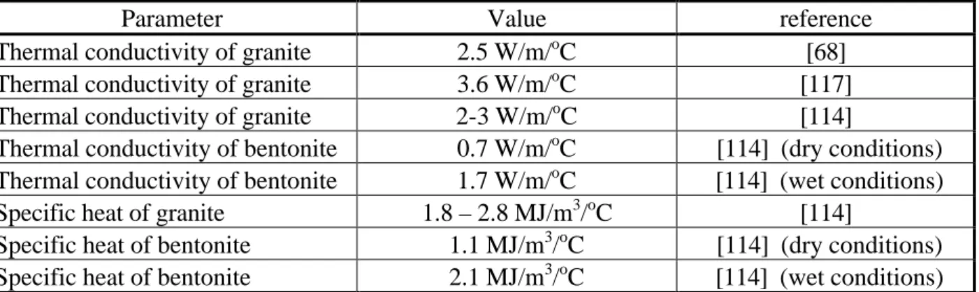
Sato et al. (ref. [114])
This report shows dimensioning calculations similar to those by Hopkirk and Wagner ([68]). It is based on a concept close to that of Project Gewähr with the exception of a few characteristics essentially concerning the canister properties and the thermal output.
The repository concept is based on horizontal galleries. The canisters are positioned horizontally along the axes of the galleries and surrounded by compacted bentonite (fig. 4). The canisters are made of steel with an outer copper shell. The fuel assemblages are packed with quartz sand. Their dimension is 4.8 m (length) × 0.822 m (diameter). The host medium is assumed to be either crystalline (Northern Switzerland basement), or sedimentary (Opalinus clay).
The mechanism taken into account is pure thermal conduction. The corresponding equation is solved with a 3-D Finite Element simulator (ADINA-T). Thermal parameters are considered to be independent of temperature. The effect of water content on the thermal parameters of the bentonite is approximated by globally modifying these parameters. Air gaps between the bentonite and the canister and between bentonite and host rock are simulated. However, radiative thermal flux is not considered, but simulated through an increase of the air conductivity.
The simulated domain is a 3-D elementary volume bounded vertically by symmetry planes (fig. 5): two vertical planes parallel to the gallery axis (one along the gallery axis, one at mid-distance between two galleries), and two vertical planes perpendicular to the previous direction (one through the canister point, one at mid-distance between two canisters). The vertical extent is 500 m above and below the gallery plane. The inner structure of the canister is represented by a simplified axisymmetric structure: concentric layers represent the fuel, the steel rack, the quartz sand and the steel and copper shells. The thickness of each layer is chosen in such a way as to conserve the volumes.
The base case shows a temperature in the bentonite of between 126oC at the canister contact and 98oC at the host-rock contact. The maximum temperature is reached after about 15 years. A maximum temperature of 100oC is computed after 800 years at the canister/bentonite interface.
Figure 4: Canisters and emplacement tunnels (dimensions of canister in mm) (from[114])
A number of variations are proposed to test the sensitivity of the results to various parameters:
- Heat generation per canister: the base-case value is 1,000 W. An increase to 1,500 W results in a significant increase in temperatures (plus 22oC at the bentonite/host rock interface).
- Tunnel spacing: the base-case spacing is 20 m. The results are shown to be relatively insensitive to an increase in spacing (temperature decrease of 10oC for a distance of 40 m), but very sensitive to a reduction (temperature increase of 40oC for a 10 m distance). - Canister pitch: a variation of the longitudinal canister spacing of between 3 m and 7 m causes little difference in the results.
- Thermal properties of the crystalline host rock are varied between 2 and 3 W/moC (thermal conductivity) and between 1.8 and 2.8 MJ/moC (thermal capacity). Likewise, the bentonite properties are varied between the following limits: 0.7 W/moC for the conductivity and 1.1 MJ/moC for thermal capacity (properties of dry bentonite), 1.7 W/moC for conductivity and 2.1 MJ/moC for thermal capacity (properties of wet bentonite). These variations result in limited temperature changes (a few degrees). - The presence of air gaps causes a small temperature increase.
- Host rock: lower temperatures are calculated for a repository in clay despite the lower thermal properties of clay. This is due to the lower ambient temperature associated with a shallower depth (600 m). For a crystalline host rock (base case depth 1,200 m), a decrease of 10oC is obtained if the depth is reduced to 900 m. This is consistent with the postulated natural gradient (3o for 100 m).
The major conclusion of this study is that the most temperature-sensitive parameters are the gallery spacing and the thermal output.
Parameter Value reference
Thermal conductivity of granite 2.5 W/m/oC [68]
Thermal conductivity of granite 3.6 W/m/oC [117]
Thermal conductivity of granite 2-3 W/m/oC [114]
Thermal conductivity of bentonite 0.7 W/m/oC [114] (dry conditions)
Thermal conductivity of bentonite 1.7 W/m/oC [114] (wet conditions)
Specific heat of granite 1.8 – 2.8 MJ/m3/oC [114]
Specific heat of bentonite 1.1 MJ/m3/oC [114] (dry conditions)
Specific heat of bentonite 2.1 MJ/m3/oC [114] (wet conditions)
Table 2: Parameter values used in the Swiss studies (values in parentheses indicate ranges of variation)
4.3. Canada
We begin by discussing two references devoted to generic thermal calculations, and continue with a modelling exercise around the Whiteshell research area.
4.3.1.
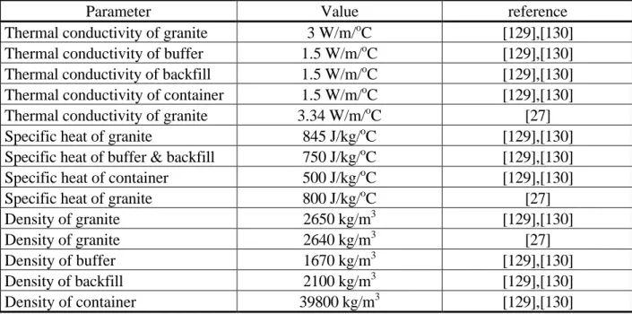
Generic thermal modelling (Tsui et al., ref. [129],[130])
These two reports present generic 3-D calculations concerning a repository situated in the Canadian shield. Two options for waste emplacement are considered:
• The “borehole” option, where the waste containers are placed in boreholes drilled from the room floor (fig. 6).
• The “in-room” option, where they are buried in a homogeneous thick layer of buffer material covering the floor of the room (fig. 9).
The first concept is closest to the Swedish one but the generic approach is common to the two concepts.
The in-room concept uses 8-m wide and 10.5 m high-galleries. A 5 m thick layer of compacted sodium bentonite and silica sand is spread on the gallery floor. The containers are buried in this material. The gallery is then filled to a height of 3.5 m with a
mixture of crushed and graded host rock and glacial clay, and the remainder of the room is backfilled with a buffer material (fig. 10).
The TWPP (Thin-Walled, Particulate-Packed) container is used. Its dimensions are 0.63 m diameter and 2.2 m in height.
Material properties used in the thermal calculations are:
• Thermal conductivity: 3 W/moC for the rock mass, 1.5 W/moC for the buffer and backfill, 1.5 W/moC for the container (modelled as a homogeneous material).
• Specific heat: 845 J/(kgo
C) for the rock mass, 750 J/(kgoC) for the buffer and backfill, 500 J/(kgoC) for the container.
• Density: 2,650 kg/m3
for the rock mass, 1,670 kg/m3 for the buffer, 2,100 kg/m3 for the backfill, 3,980 kg/m3 for the container.
The initial thermal load is 297 W per container, making an average areal load of 11.4 W/m2 for a pitch distance of 2.6 m between containers and 14.2 W for a 2.1 m distance.
The aim of the calculations is to obtain a detailed 3-D thermal and mechanical response in the near field. To achieve this precision, a “unit-cell” is represented in the calculations. It represents a volume of host rock and gallery, bounded vertically by four symmetry planes: two are parallel to the gallery axis, one at mid-distance between galleries, one along the gallery axis; two are perpendicular to the gallery, one across the containers and one at mid- distance between two container rows. The top boundary is the ground surface, and the bottom boundary is 2,000 m below the gallery level.
The concept of unit cell is valid for containers situated near the centre of the repository, and conservative for containers situated near the repository boundaries.
Boundary conditions are adiabatic on the vertical boundaries and fixed temperatures on the top and bottom boundaries, with an average gradient of 12oC/km.
The Finite-Element code ABAQUS is used for the calculations. A very fine discretization is applied in both studies, particularly in the “borehole” option, which represents the vicinity of the boreholes with great precision: about 10,000 elements and 12,000 nodes are used, the smallest ones approximately 0.15 m × 0.20 m × 0.40 m (fig.
8, 11).
Results: for the in-room option, a maximum temperature increase of 83o
C is found at the outer container surface after 25 years. This temperature depends strongly on the distance between containers: the temperature increase drops to 70oC when the distance is lengthened from 2.1 m to 2.6 m.
Figure 6: Schematic illustration of the Canadian concept of a nuclear fuel waste disposal vault with the boreholes emplacement option (from[129])
the near-field of a disposal vault (from[129])
central part of the unit cell (from[129])
Figure 9: Schematic illustration of the Canadian concept of a nuclear fuel waste disposal vault with the in-room emplacement option (from[130])
Figure 10: Dimensions of a unit cell for the
4.3.2.
Thermal modelling of the Whiteshell area
The work reported in ref. [27] is a detailed, site-specific modelling exercise, of which thermal calculations are only a small part. The disposal concept involves a network of horizontal tunnels and galleries at a depth of 500 to 1,000 m in the Canadian shield. The containers are to be buried according to the in-room or borehole schemes discussed in the previous section. However, unlike the previously discussed studies, this work uses a less detailed near-field representation and focuses on the modification of the local and regional flow field.
All modelling is based on the Equivalent Porous Medium concept, where major fracture zones are explicitly taken into account. Calculations are made with the Finite-Element code MOTIF. The rock mass is structured in 5 homogeneous layers where permeability as well as porosity decrease with depth (respectively from 10-15m2 to 10
-21
m2 and from 0.005 to 0.003). Permeability is anisotropic in the two top layers, with a vertical value 5 times higher than the horizontal one. Major fracture zones are explicitly represented as porous media with a thickness of 20 m and a permeability two to six orders of magnitude higher than that of the surrounding rock and a porosity 1.6 to 33 times higher.
Thermal parameters are as follows: thermal conductivity of the rock: 3.34 W/moC; specific heat: 800 J/(kgoC); rock density: 2640 kg/m3. An anisotropic dispersivity tensor is included: 6 m for the longitudinal dispersivity, 0.6 m for the transverse dispersivity. For non-isothermal fluid flow, water density depends on temperature (quadratic law) and on pressure (linear law).
The concept of a waste-exclusion zone is used to characterise the region extending horizontally from the side of the waste-emplacement area closest to a fracture zone up to the fracture zone.
First, a two-dimensional model is developed : a 27 km × 4 km cross-section corresponding approximately to a groundwater flow line. Thermal boundary conditions are prescribed temperatures, according to a geothermal gradient of 11.5 oC/km, and a surface temperature of 6 oC. The repository is represented as a line source at a depth of 500 m with a thermal output of 11.6 W/m2. The maximum perturbation of the flow by temperature occurs around 10,000 years. The water velocity is increased by, at most, a factor of 10 close to the vault, but this effect decreases rapidly with distance. The maximum velocity increase in fracture zones is about 75 %. No formation of convection cells is shown to occur (remember that the permeability at the repository level is about 10-12m/s). The travel times from the vault to the surface vary from 890 years to 2.4 107 years. These values do not to any great extent depend on the thermal effect : the shortest
travel times vary between 1,600 years (no thermal effect) to 1,300 years (geothermal gradient only) and 890 years (thermal source term). The influence on the longest travel times is negligible, because in the regions that contribute most to the transfer times, there is no temperature change.
The three-dimensional approach starts with a regional model covering the whole Whiteshell Research Area, down to a depth of 4 km. A local model is then derived on a refined mesh with boundary conditions extracted from the regional model. The local model covers 10 km × 9 km and extends to a depth of 1.5 km. The Finite-Element mesh contains 15,144 elements and 16,944 nodes. The thermal boundary conditions are the same as in the 2-D model. The heat source is uniformly spread over a plane. The results of the thermal calculations are very close to those of the 2-D model: the maximum temperature increase is 72 oC after 8,800 years and drops back to zero after about 100,000 years. Water velocities in the fracture zones are increased by, at most, 50 % due to thermal effects. In sparsely fractured zones, where the velocities are about 3 orders of magnitude lower, an increase by one order of magnitude is found. Close to the vault, the maximum increase is by 30 times, and the average increase is 100 % after 2,000 years. The velocity direction may be inverted locally, but the average angular deviation is only 15o. Far from the vault (at a distance of 1 km), the maximum increase in velocity is again by a factor of 30, but the average increase is only 50 %. The maximum angular deviation is 145o. No convection cells are found to occur in fractures. The maximum reduction in travel times is about 24 %. Globally, the average reduction in convection times is 25 %. The largest reduction is 50 %.
The conclusions of the thermal aspect of this work are quoted directly from the report:
“Although the vault heating causes a large perturbation in the groundwater velocity near the hypothetical vault which lasts as long as 100,000 years, the majority of the convective transport paths leading from the vault to discharge locations at the surface are not significantly affected by the vault heat. The reason is that the movement of groundwater through the sparsely-fractured rock is usually so slow that the convective travel time from the vault to the surface is generally much longer than the duration of the velocity perturbation.
Thermal convection in the groundwater flow field surrounding the vault, due to heat generated by the fuel waste in the vault, may or may not be important depending upon the size of the waste-exclusion distance. For a 46 m waste-exclusion distance, thermal convection due to waste heat does not significantly affect the overall groundwater travel time from the vault to the surface. For a 10 m exclusion distance and for no waste-exclusion zone, there is some effect and this results in reduced travel times”.
Parameter Value reference
Thermal conductivity of granite 3 W/m/oC [129],[130]
Thermal conductivity of buffer 1.5 W/m/oC [129],[130]
Thermal conductivity of backfill 1.5 W/m/oC [129],[130]
Thermal conductivity of container 1.5 W/m/oC [129],[130]
Thermal conductivity of granite 3.34 W/m/oC [27]
Specific heat of granite 845 J/kg/oC [129],[130]
Specific heat of buffer & backfill 750 J/kg/oC [129],[130]
Specific heat of container 500 J/kg/oC [129],[130]
Specific heat of granite 800 J/kg/oC [27]
Density of granite 2650 kg/m3 [129],[130]
Density of granite 2640 kg/m3 [27]
Density of buffer 1670 kg/m3 [129],[130]
Density of backfill 2100 kg/m3 [129],[130]
Density of container 39800 kg/m3 [129],[130]
Table 3: Parameter values used in the Canadian studies (values in parentheses indicate ranges of variation)
4.4. United Kingdom
The United Kingdom has provided some pioneering contributions on the subject of thermal effects in crystalline media. This is reflected in the work by the Harwell group, from which we have extracted a few representative examples. The emphasis is nowadays more on the design of a ILW repository with possible applications to some aspects of HLW management ([96]).
Bourke (ref.[21]) shows a very early approach to the problem of thermal loading. With an initial output of 10 kW per waste container, a temperature rise of the order of 1,000oC is considered, with a probability of melting of the rock as well as of the waste package. Corrective measures are proposed in terms of initial cooling and “waste dispersion”.
In Hodgkinson ([65]), temperature evaluations are based on a less drastic heat production, obtained through an appropriate combination of initial cooling and waste package spacing. A simplified model of the heat source is used: heat is uniformly released over a spherical volume. This allows an analytical solution of the heat transfer equation to be developed.
The same modelling approach is used in Beale et al. ([12]) to represent the following set-up: the containers have a length of 3 metres and an initial thermal output of 1 kW. They are arranged in a cubic set-up, aimed at minimising the length of the galleries, and based on a postulated higher probability of finding a continuously sound rock mass in the vertical than in the horizontal direction. Thermal parameters for the granite are taken from an in-situ heating experiment on a Cornish granite, performed on a 5 m scale: the thermal conductivity is 4 W/moC and the specific heat 2.1 MJ/m3 oC.
Hodgkinson ([66]) presents calculations to assess the influence of buoyancy flow on the transfer of radionuclides. The fractured medium is treated as an equivalent continuous medium, in which the flow is Darcian. Heat transfer is by conduction only. As in the previous references, a hypothesis of axial symmetry is used, and the heat source is treated as uniformly spread throughout a sphere. Thus, an analytical approach is possible to temperature as well as to pressure and stream functions. A regional gradient is superimposed in some examples. This study shows the possibility of flow paths to the surface being established due to density effects, with travel times on the order of a few hundred to a few thousand years (see fig. 12).
Figure 12: Thermal pathlines (from[66])
In Bourke and Robinson ([22]), the same approach is extended to compare the transit times associated with natural water circulation to those due to buoyancy flow. The results are of a generic nature and highly dependent on hypotheses made on the parameters, but the general conclusion is that thermally driven flow will dominate over natural flow for several thousand years. The effects of repository geometry and depth as well as of cooling time are studied. The possibility and consequences of a thermal load associated with ILW is also considered.
Parameter Value reference
Table 4: Parameter values used in British studies
4.5. France
4.5.1.
CCE “Thermal-loading” study
This study (ref.[24]) may be considered as the first French effort to model the conditions around a realistic repository. The emphasis of the study is on the effects of thermal loading, and on the maximum load admissible in order to maintain these effects at an acceptable level. The study covers three types of geological formations: clay, granite and salt. Below, we briefly review the approach and the results obtained for granite.
The exercise aims at simulating a realistic geometry, based on a design study. The depth of the repository is 1,000 m. It includes 82 galleries, each 2,300 m long, and separated by 26-m intervals. 100 m deep boreholes, 30 m apart, contain 5 canisters each. The initial heat release is close to 990 W per canister. This arrangement leads to an average load of 5.8 W/m2. The influence of the buffer material properties is studied at the local scale. In global calculations, the buffer is assumed to have the same thermal properties as the granite.
Thermal parameters have the following values: 2.5 W/moC for thermal conductivity and 2.2 MJ/m3 oC for specific heat. These parameters result from a compilation of values obtained in the US, UKAEA, Stripa, and at various Far-Eastern and French sites. A weak variation of these properties with temperature is mentioned, but viewed as negligible in the range of the obtained temperatures.
Two modelling scales are considered: local (temperature distribution near the canisters) and global (granitic formation).
The local-scale calculations are done in two stages: first, an axisymmetric Finite-Element model computes the effect of a single container, situated near the centre of the repository. In the second stage, the influences of each elementary source are summed. This allows the effect of the borehole spacing and the rate at which containers are put in place to be investigated.
The global-scale model is based on an axisymmetric approximation: the repository is represented as a homogeneous disk with a thickness of 100 m and a radius of 1,300 m, in which the heat is homogeneously released. This model uses a Finite-Element code based on a quadratic spatial approximation.
![Figure 1: Diametral plane through the axis of a storage tunnel showing (hatched) the domain of the fine scale (cylindrical) model (from [68])](https://thumb-eu.123doks.com/thumbv2/5dokorg/3346517.18836/24.892.204.666.152.625/figure-diametral-storage-tunnel-showing-hatched-domain-cylindrical.webp)
![Figure 2: Plane perpendicular to storage tunnel axes showing (hatched) the domain of the coarse scale (Cartesian) model (from [68])](https://thumb-eu.123doks.com/thumbv2/5dokorg/3346517.18836/25.892.234.643.149.636/figure-plane-perpendicular-storage-tunnel-showing-hatched-cartesian.webp)
![Figure 3: Sectional views of a typical 50 m length of storage cavern in the repository for low and intermediate level waste showing different phases of filling (from [68])](https://thumb-eu.123doks.com/thumbv2/5dokorg/3346517.18836/26.892.225.739.135.523/figure-sectional-typical-storage-repository-intermediate-different-filling.webp)
![Figure 4: Canisters and emplacement tunnels (dimensions of canister in mm) (from[114])](https://thumb-eu.123doks.com/thumbv2/5dokorg/3346517.18836/28.892.232.674.144.541/figure-canisters-emplacement-tunnels-dimensions-canister-mm.webp)
![Figure 5: Three-dimensional finite-element mesh (from[114])](https://thumb-eu.123doks.com/thumbv2/5dokorg/3346517.18836/29.892.231.658.266.928/figure-three-dimensional-finite-element-mesh-from.webp)
![Figure 6: Schematic illustration of the Canadian concept of a nuclear fuel waste disposal vault with the boreholes emplacement option (from[129])](https://thumb-eu.123doks.com/thumbv2/5dokorg/3346517.18836/32.892.305.596.202.560/figure-schematic-illustration-canadian-concept-disposal-boreholes-emplacement.webp)
![Figure 9: Schematic illustration of the Canadian concept of a nuclear fuel waste disposal vault with the in-room emplacement option (from[130])](https://thumb-eu.123doks.com/thumbv2/5dokorg/3346517.18836/33.892.302.569.211.570/figure-schematic-illustration-canadian-concept-nuclear-disposal-emplacement.webp)
![Figure 12: Thermal pathlines (from[66])](https://thumb-eu.123doks.com/thumbv2/5dokorg/3346517.18836/37.892.251.639.516.780/figure-thermal-pathlines-from.webp)
