Scientific Press International Limited
Dam Safety Problems Related to Seepage
Nasrat Adamo1, Nadhir Al-Ansari2, Varoujan Sissakian3, Jan Laue4 and Sven Knutsson5
Abstract
Dangerous occurrences affecting dams take multiple forms, but seepage caused cases are the most numerous. Some of the cases are related to the geology of the foundation and the magnitude and type of discontinuities in the rock mass of the dam. Other are mainly due to of construction material in earth fill dams. Seepage occurs in all earth fill dams regardless of its materials, and seepage water can daylight at the downstream face causing erosion, piping and sloughing and instability; unless certain measures are taken. Instability can be controlled mainly by adding, filter material zones at the contacts with the clay core, chimney filter drain at the downstream part of the dam, filter zone or bench at the toe together with the drainage blanket under the downstream part of the dam. Seepage within the dam is enhanced by cracks which may result from uneven settlement of the dam due to different elastic behavior of the foundation materials, hydraulic fracturing, and differential settlement of parts of the dam or due to ground shaking in earthquakes. Preferential seepage paths can develop in such cracks, especially if the fill material is dispersive or suffusive. Similarly, such paths may develop along the contact surfaces of conduits installed under dams as outlet structures due to the low degree of compaction as a result of narrow trench dimensions. Using properly designed filter and drainages can reduce seepage quantities and the erosive force which causes internal erosion. In dam’s foundation grout curtains or other type of cutoffs can reduce the hydraulic head and hence uplift under the dam and hinder seepage. Drainage, however, remains as the most efficient method in controlling this uplift in artesian conditions under dams, especially under concrete gravity dams. Generally, such drainage may take the form of drainage blanket and use of filters material.
1 Consultant Dam Engineer, Sweden.
2 Lulea University of Technology, Lulea, Sweden.
3 Lecturer, University of Kurdistan Hewler, and Private Consultant Geologist, Erbil. 4 Lulea University of Technology, Lulea, Sweden.
5 Lulea University of Technology, Lulea, Sweden.
Article Info: Received: June 9, 2020. Revised: June 18, 2020.
Keywords: Seepage, Internal Erosion, Piping, Sloughing, Hydraulic Fracturing,
Filters, Chimney Drain, Drainage, Uplift.
1.
Introduction
The success of any dam project and its safe and fruitful performance can be achieved only, by systematic step by step procedure following prescribed disciplines. This begins with site selection of a promising site that fulfills topographical and geological requirements. From the start, the planning and design phases follow an interactive procedure with interconnected phases in a logical way. Hydrological studies, no doubt will decide on the availability of water in the river, whether during floods or low water seasons, but only by using hydraulic flood routing and judging from the topography of the site total storage can be decided. Following this, the magnitude of sedimentation of the reservoir will decide on the, dead storage, live storage of the reservoir and the various operation water levels and the selection of the maximum design discharge of the spillway and other outlet structures. All these questions fall within the scope of hydraulic engineering and were discussed in a previous paper [1]. Designing the dam to answer other hydraulic matters will depend on the type of the dam, its material of construction and foundation conditions. These involve seepage through the body of the dam, under-seepage in the foundations, uplift pressure on the dam base …etc. Hydraulic problems may arise during the operation of a dam which can threaten its safety. Such hazardous problems that need careful studies, and practical solutions are; seepage problems, scouring and cavitation induced by high velocity flow, sediments and debris blocking outlet facilities or even jamming of gates of outlet structures such as spillways are examples. An attempt is made in the following paragraphs to review anticipated or actual hydraulic problems related to seepage that are foreseen during design phase or appear later on during operation of dams, as these problems form one of the most common causes of dam failures and incidents.
2. Failure Statistics of Dams due to Hydraulic Problems
Well documented registers of dams’ failures and incidents have been published by ICOLD. These registers show that during the last century, a rapid increase in large dams building occurred. From the given statistics, it can be seen that only about 5,000 dams had been built all over the world up to year 1950, but at the end of the 20th century, the number of large dams reached approximately 45,000 dams. The introduced strict safety rules and regulations combined with new technologies and innovations developed in the design and construction fields reduce the percentage of dam failures to just 0.5% nowadays from a figure of 2.2% before 1995. Nevertheless, each failure case can make big news in the media due to the large social, economic and environmental losses. Ideally, a zero percentage should be aimed at if possible.
The majority of existing dams today are embankment dams totaling 77% of all dams in the world, of these 64% are earth fill and 13% rockfill dams concrete dams and other type dams make up the remaining 32, refer Figure 1 [2].
Figure 1: Percentage of all types of dams in the world, excluding China [2].
It follows that the number of failure cases in embankment dams hydraulic exceeds by far the failure cases in the other ones, which can be observed from Figure 2.
Figure 2: Number of failures by types and height of dams, excluding China [3].
The bias in the above statistics towards embankment dams with 77% failures can be explained by the fact that the majority of dams constructed so far are embankment dams compared to concrete dams. Moreover, earth fill dams are more sensitive to hydraulic problems than the concrete dam due to the nature of their
construction materials and the relatively weaker foundation on which they are founded.
The most common hydraulic problems that have caused dam accidents (failures and incidents) up to 1995 are shown in Figure 3. This is based on an (ICOLD) report published in 1995 under the title “Dam Failures-Statistical Analysis (Bulletin 99)”.
Figure 3: Causes of failures in embankment dams [3].
A study was conducted in 1998 by Foster, Fell and Spannagle from the University of New South Wales on Large embankment dam incidents up to 1986 and based on the (ICOLD) World Register, that includes a database of 11,192 dams; it showed that out of total 136 large dam failures, 121 cases are attributed to hydraulic problems. These dams cover a broad range of age, construction techniques, and foundation conditions. Table 1 shows statistics of embankment dam failures for different modes of failures. These statistics indicate that piping caused failures are the majority of all failure cases of embankment dams, and one-half of all piping failures are associated with conduits through the dam body or its foundations. Conduits are sources for discontinuities and are difficult to properly compact around. Moreover, nearly 50% of piping failures through the embankment have occurred during first filling and 64% within the first 5 years of operation. For piping through the foundation, nearly 25% of the failures occurred during first filling and 75% within the first 5 years of operation.
Table 1: Summary of embankment failures.
Mode of Failure Number of cases Percent failures (where known)
All failures Failures in operation
All failures Failures in operation
Overtopping 46 40 35.9 34.2
Spillway/gate 16 15 12.5 12.8
Subtotal 62 55 48.4 47.0
Piping through embankment 39 38 30.5 32.5
Piping through foundation 19 18 14.8 15.4
Piping from embankment into foundation 2 2 1.6 1.7 Subtotal 59 57 46.1 48.7 Slides 7 5 5.5 4.3 Earthquakes/ Liquefaction 2 2 1.6 1.7 Unknown 8 7
Total number of failures 136 124
First filling is considered the first true test of the embankment dam under hydraulic loading conditions. If a dam is poorly constructed or contains flaws and defects, first filling will likely expose these weaknesses. However, some piping failures can develop slowly over time (such as internal erosion into a karstic foundation). As indicated earlier, nearly 25% of failures occur after5 years of operation [4].
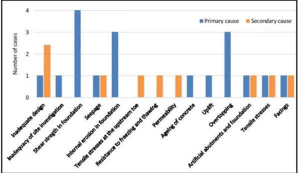
The main causes of failure in concrete dams, according to “Bulletin 99” ICOLD (1995) are summarized as shown in Figure 4 and Table 2 [5].
Figure 4: Main causes of failure of concrete dams.
Table 2: Main causes of failure of concrete dams.
Details Number of Cases Primary Cause Secondary Cause
Design Inadequate design 1 14
Foundations
Inadequacy of site investigations 1 Shear strength of foundations 4
Seepage in Foundations 1 1
Internal Erosion in Foundations 3
Tensile stresses at the upstream toe 1 Resistance to Freezing and Thawing 1
Uplift 1 Dam Permeability of Concrete 1 Aging of Dam 1 Overtopping 3 Tensile Stresses 1 1 Facing 1 1 Artificial abutments and foundation
3. Embankment Dams: Hydraulic Seepage Problems
All embankment dams have some seepage, and many suffer from excessive seepage. As water in the reservoir seeks paths of least resistance through the dam body, and its foundation, it may pose some hazards on the dam safety. Excessive seepage may lead to dam failure if it is not treated and controlled properly. If seepage flow is allowed to continue unhindered in appreciable quantities, then the seepage force may erode fine soil particles and wash them out causing piping failure of the dam in internal erosion process or create uplift problems. Seepage, therefore, may be considered as one of the most common safety hazards for embankment dams, and many failures of such dams have been recorded in dam failures registries. The basic problem facing designers and operators is trying to discern how seepage is affecting a particular dam and what measures, if any, must be taken to ensure that the seepage does not develop and adversely affect the safety of the dam.
Protection against such hazard should be done in the design stage, and if it appears during the dam’s lifetime, the case must be investigated carefully, and the application of the necessary remedies should be done early to prevent it from developing into failure conditions. Seepage through the dam body can emerge anywhere on the downstream face, above the toe or on the downstream abutments, at elevations below the normal pool. In such a case the phreatic surface should be
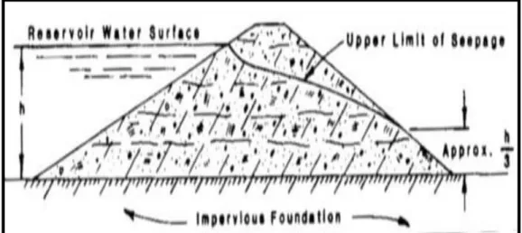
lowered in order to confine its exit point inside the dam body. For the simplest case of a homogenous dam on an impermeable foundation, the
picture of seepage through the dam body, without using any measure to lower the phreatic surface is as given in Figure 5.
In this type of dams, there is the danger of sloughing in the downstream slope and internal erosion leading to failure when the water level in the reservoir is high and pore pressure is also high. The same thing will happen as a result from the rapid draw of the reservoir and the upstream slope is saturated. Both slopes may have to be made very flat to avoid such conditions, or to add filters at the toe, or lay a drainage layer or drainage blanket within the base at the downstream, as shown in Figure 6 and Figure 7.
Figure 6: Using Rockfill toe and filters.
Figure 7: Using horizontal drainage blanket.
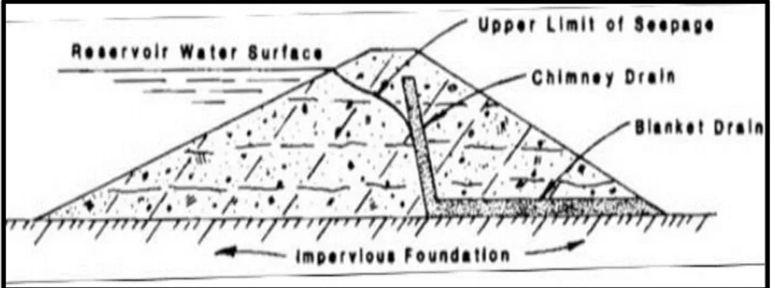
The last alternative is to add chimney drain within the dam to intercept the phreatic surface inside its body, and relieve seepage water afterwards from the downstream in a safe way as in Figure 8.
Figure 8: Using chimney drain.
Homogenous embankments may be used for low embankments, but not for high dams as safety hazards of dams’ increase with increasing height and storage. As far as seepage is concerned, the current design procedures call for minimizing seepage and limiting its hazards instead of eliminating it completely, which may prove in most cases to be very costly or even impossible.
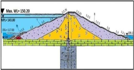
The need for constructing large dams has led to development of zoned fill dams; where different types of soil materials may be used and placed in such a way to protect from seepage. First of all, an impermeable core in the middle, which can be of clay, or a diaphragm (concrete or asphaltic concrete), will act as the main defense against seepage. On the upstream and downstream sides of the core, filter zones should be also designed and added to secure against any residual seepage or leaks through cracks in the core resulting from earthquakes, settlement or hydraulic fracturing. Seepage water is then collected and removed in one of the safe ways as indicated previously. It can be said, therefore, that the design philosophy has changed to controlling seepage and lowering the saturation of the phreatic surface and minimizing seepage quantities by incorporating filters and drainage elements, thus permitting steeper slopes and consequently higher dams. The extra safety drawn from using filters can also help in selecting semi impermeable soils and diaphragm for the core provided that the filter’s arrangement and design fulfil the safe exit of the seepage water. One such case can be cited from the construction of Haditha Dam in Iraq, where dolomite fill is used for the central core with asphaltic concrete diaphragm, which is followed by the deep grout curtain in the foundation, refer to Figure 9 [6].
Figure 9: Cross section of Haditha Dam showing dolomite core and asphaltic concrete diaphragm.
In this Project, the permeability of the dolomite core varied between 1.1x10⁻³ and 3.1x10⁻⁵cm/sec which makes it permeable to semi-permeable. While permeability
of the asphaltic concrete diaphragm is below 1.0x10⁻⁷cm/sec. Controlling seepage through the foundations of the dam, being an embankment or concrete dam, is important to prevent the foundation material from piping and washing away, which could result in structural failure due to loss of support. At the same time, it is important to control seepage in order to reduce uplift pressure.
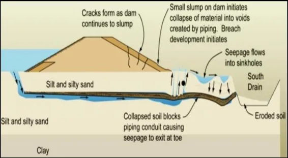
Measures that can be taken vary according to each case from using impervious upstream blankets, and/or grout curtains or diaphragms and cutoff trenches under the dam itself. These measures will reduce uplift, lengthen the seepage path and reduce the exit gradient of the seepage water at the dam toe preventing the formation of boils, which are signs of internal erosion in the foundation material [7]. Seepage problems remain the same for both permeable foundations of silts or clays as for rock foundations, which contains solution channel, rock jointing and cavities. Figure 10 represents a case of under seepage of an earth fill dam on silt and silty sand foundation.
Figure 10: Piping through dam foundations.
4. Concrete Dams: Hydraulic Problems as Consequence of
Seepage
Seepage problems take special weight in the safety considerations of concrete dams. They are normally subject to various influences, which are related to their safe operation and existence such as; deformation of the foundation, strength of their materials, stability conditions, and aging. Seepage, however, plays a special role in unison with all these factors exasperating them in addition to its own negative role. The adverse effects of seepage on concrete dam safety are mainly from the uplift pressure on the dam base, which can be easily produced because of dam foundation seepage. The uplift pressure can decrease the anti-sliding force of the dam and threaten its stability. Moreover, concrete and masonry dams can be affected by the percolation of seepage water through the dam body in one or more ways. It may percolate through cracks in the dam itself which can cause leaching of its material and creates weakness planes. The historical accident of Bouzey Dam in France was directly related to this phenomenon. Seepage through the foundation can result in internal erosion of its material in addition to affecting the sliding stability of the dam. One research paper lists three sources of negative impacts, which can result from seepage, namely:
1) Dam seepage pressure shown as uplift pressure in dam foundation and seepage pressure within the dam body itself. Both are caused by seepage water and have certain influences on dam stability, deformation, and stress. 2) Dam leakage causes the water to take the fine particles out of the dam body
and form a seepage passage, which endangers the stability of the dam. 3) Upstream impoundment cannot only seep through the dam body and
foundation, but also seep downward around the bank slopes at both ends of the dam [8].
The case of Bouzey Dam, which failed on Saturday 27th April 1885, is a good example of more than one factor of those mentioned above acting together. The dam was a straight masonry gravity structure with a length of 528 meters which was built on the L’Avière River, a tributary of Moselle River near Epinal in Eastern France. When the dam failed, the ensuing flood-wave in the valley of the L’Aviere River resulted in drowning 85 people and causing extensive damage on canal works, railway structures, bridges, villages and farms in the downstream.
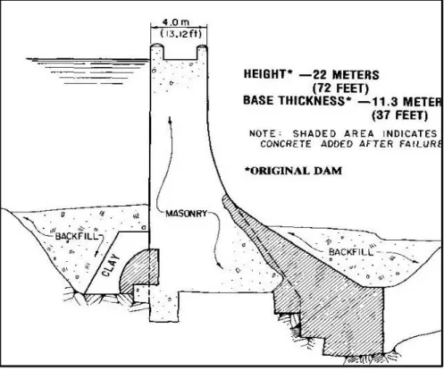
The original design was to have a height of about 20 meters with a crest thickness of about 4 meters. This thickness was to be carried down to a level about 4.3 meters below the top of the dam where the downstream face was to begin a concave circular curve extending down to the toe resulting in base thickness of about 11.3 meters. Construction was started in 1878, subsequently, a decision was carried out to increase the height about 2 meters without altering the other dimensions of the dam disregarding the “middle third principle” which states that on any horizontal plane within a gravity dam, the resultant of forces should act within the middle third. This is to ensure that the stress would be compressive at all points on that plane otherwise tensile cracks may be formed. Late in 1881, the work was completed, and the impoundment was started. Leakage soon appeared, totaling approximately 57 liters per second. About a year later, two cracks were discovered in the dam. As a safeguard, the allowable operational levels of the reservoir were lowered. On March 14, 1884, with the reservoir level about 2.7 meters below the maximum, a 137-meter long section of the mass slipped abruptly on its base and moved downstream as much as 380 millimeters. This was accompanied by a rapid increase in leakage to about 108 liters per second, but no remedial measures were taken. In the fall of 1885, about 1.5 years after this mishap, the reservoir was drained and many cracks in the upstream face were discovered, with one break extending 91 meters horizontally. Evidently, cracking had also severed the dam from its cutoff wall, which extended into the foundation at the heel. This crack at the base was then covered by a longitudinal block of masonry, which in turn was sealed with puddled clay. The downstream toe was extended outward and downward by addition of a masonry mass which roughly doubled the dam’s base thickness. It gave a flatter slope to the lower downstream face, keying into the original mass at about mid height. The cracks in the old masonry were grouted, and drains were installed. The remedial program was finished in September 1889, Figure 11.
Figure 11: Bouzey Dam profile after modification and remedial program.
In November 1889, reservoir impoundment was begun. When the water level reached maximum, the crest deflection was nearly 25 millimeters at some points. On April 27, 1895, the entire top part of the dam - a mass roughly 10 meters high and 183 meters long - broke away and loosed a torrent of water upon the village of Bouzey. Continuing its rush down the valley of L’Avière River, the flood left several other villages in ruins. Among factors related to the failure, water pressures inside and under the dam were undoubtedly contributory. The sandstone foundation was cracked, and the cutoff at the heel was not extended adequately into the rock. Both of these conditions could allow water under the structure. Faulty masonry joints could permit similar leakage at higher elevations. Detrimental hydrostatic pressures, therefore, could have developed easily. Such pressures, if applied in the upper parts of the dam where structural thickness was marginal, may have been a primary source of trouble. Yet the weakening of the dam appeared to be progressive. Failure did not occur as soon as the reservoir was full, but instead, many months passed before the signs of distress were discovered. After the repairs had been completed in 1889, an even longer period ensued before the collapse, even though the storage levels were kept high. Investigators of the disaster wondered whether other, more subtle, forces of destruction were at work. In the search for a cause of failure, the mortar used to bond the masonry was an outstanding suspect. There is apparently no question that its quality was inferior. If the preparation of lime mortar was done carelessly, as was alleged in this case, some of the lime may have
remained unslaked or only partially slaked. If incorporated into a structure in this unstable state and then exposed to wetting, the lime will complete its slaking and tend to expand in the process. Used in Bouzey Dam, this could have resulted in weak mortar joints constituting potential planes of separation, which were good conduits for seepage. Whether the cracking in the dam followed such planes is not clearly evident.
Various possible causative factors may have acted together. The comparatively thin masonry section would have been susceptible to tilting away from the thrust of the reservoir water, accompanied by opening of cracks at the base and in the masonry and by gradual deterioration of mortar. Even acknowledging that the design dimensions were marginal, including the lastminute increase in height, one unavoidable conclusion is that defective materials and poor workmanship deserve much of the blame for the Bouzey Dam disaster [9].
One case which highlights the problems created by seepage water seeping into concrete dam body and result in costly remedial works, is that of Ajba Dam. This dam is part of the hydro-power plant Plave on the Soča River in Slovenia, completed in 1940. The dam has structural height of 39m, and crest length of 72m. It may be classified as a combination of a barrage and gravity dam. The retaining structure consists of four massive piers with three large gates. The piers are connected at elevation 111.5m a.s.l. with bridging elements in pairs, one at the upstream and one at the downstream side of the piers. The small bridges are arched shaped and made of reinforced concrete. The foundation level is 92.1m a.s.l. and the roofing structure with the mechanism for opening and closing the gates is at the 120.0m a.s.l. The roofing structure or ‘upper deck’ is constructed on top of the four extended piers, and it is made of arching girders, fixed with cross girders and reinforced concrete plate. The usual water level is at 106m a.s.l, refer to Figure 12.
.
Sixty-five years of exploitation caused extensive damage on concrete: e.g. cracks, corrosion of reinforcement, damages of construction joints and stone blocks, deterioration due to freezing and thawing cycles … etc. In the concrete elements of the dam most of the damage was caused by the degradation effect of frost cycles of seepage water penetrating through faulty construction joints and cracks. These damages were very severe at locations where constant leakage and wetting of concrete had occurred. Open construction joints and numerous cracks were clearly visible on all sections of the dam. Most of them were initially caused at the time of construction due to the technology used in construction. At these cracks, leakage was observed where the width of cracks was up to 3mm. It was necessary to seal the open joints and cracks to stop seepage water and re-establish integrity of each construction elements and prevent further degradation of the concrete and the reinforcement.
Based on the findings of the visual inspection and laboratory tests, the scope and cause of damages were established, and an extensive program of rehabilitation was then carried out. Among the various applied measures; sealing all cracks was foremost, using polymer cement mortars applied manually. On large cracked sections, the mortar was applied using shotcrete, and new protective layer of concrete was applied over the exposed reinforcement bars. Concrete surfaces were smoothed with fine-polymerized cement mortar. Protective coating of polymerized
cement was applied; waterproofing layer was carefully placed. Five years after rehabilitation works were finished most of the former cracks and
joints are still closed and not visible. At some locations, especially where leakage was not entirely prevented, the cracks and flowstone deposits reappeared [10]. Early experience with Rolled Compacted Concrete dams construction involved problem of seepage water leaking from the dam body, especially at the horizontal joints between lifts, which caused alarm. One of these early cases was that of the Willow Creek Dam located on Willow Creek in at Oregon in USA east of the city of Heppner. It was the first major dam in the United States constructed of roller-compacted-concrete. The dam's original purpose was primarily to store water for flood control, but also to serve recreation, fishing and wildlife and irrigation uses. The reservoir level can be a maximum of 644.2m a.s.l. and a minimum of 628.8m a.s.l. for a total usable storage capacity of 12 x 106m3. Flooding was common for this stream, and a major flood had killed 247 people of Heppner's population in June 1903, which had resulted from a thunderstorm and known as the Heppner Flood of 1903. The observed Creek flow was then 1,000m3/s.
The dam was constructed by the US Army Corps of Engineers between November 1981 and February 1983. Construction was completed nearly on schedule, despite the workers initially being unfamiliar with the materials, processing, and techniques. The cost of the dam was about $35 million, 330,000 cubic meters of concrete were finished in less than five months at about $17 per cubic meter which included additional efforts to correct defects.
As the reservoir began filling significant leakage was evident through the seams of the layers of concrete. The reservoir was drained, and a $2 million remedial effort
included injecting grout through bores drilled from top to bottom. The initial rate of leakage was 33 cubic meters per second. After remediation, the leakage was less than 11 cubic meters per second. Concern over the dam's safety has continued ever since, especially with the memory of the 1903 flash flood [11]. Figure 13 shows a view of this dam.
Figure 13: View of Willow Creek Dam [12].
Controversy over these dams has continued since its construction. Paradoxically, given the tragic loss of life in 1903; the initial proposal to build Willow Creek Dam was never popular here. The impoundment was regarded with suspicion. One of the reasons they say that the dam leaked like rusty bucket. Moreover, seepage frightened some and resulted in vegetation so dense on its concrete face that a local logger threatened to graze sheep there, which was actually done as seen from photographs, refer to Figure 14 [13]. In 1988, a Corps of Engineers lake scientist warned that water and chemicals from the nutrient-rich reservoir were dissolving the concrete as it seeps through. An inspection team later declared the dam safe, but the Corps said water action eats up to 20 metric tons per year of the dam's 900,000ton weight, though not enough to weaken it. Officials in Oregon consider seven dams across the state to be in “unsatisfactory" conditions. According to a statement made by Diana Enright, the spokeswoman for the Oregon Water Resources Department. Enright provided a list of seven troubled dams in Oregon; one of them was Willow Creek Dam. All seven Oregon dams deemed “unsatisfactory” for safety and high hazard dams.
While it’s hard to find out which dams have the potential to fail, a federal database lists those that would have catastrophic consequences if they did [15].
Figure 14: Leakage signs on the downstream side of the dam, and at the toe observe the heavy vegetation and the grazing goats [13].
5. Internal Erosion in Embankment Dams
Internal erosion is one of the most common modes of embankment dam failures, which is caused by extreme conditions of seepage. Inspecting the statistics shown in Figure 3, shows that the total number of all dam failures and incidents by the internal erosion amount to 40%, adding together failures in the foundation and body of dams. In order to give a good insight of this mode of failures, its causes and forms, elaboration may be necessary, and some details are presented in the following:
5.1 Definition
Internal erosion is one of the main causes of dam failures, and one of the most difficult potential failure mechanisms to predict. Normally, seepage occurs in every earth fill dam, but it is uncertain when the seepage occurs and which path it will take. Many of these paths may never be seen or detected during the life of an embankment. The real problem starts when the seepage begins to dislodge and move particles of soil from one location to another in what is called internal erosion. This can be of concern for the safety of an embankment dam, and at times, one concern for concrete dams and other concrete hydraulic structures founded on rock or soil. Many geotechnical problems; such as differential settlement, core cracking or hydraulic fracturing are associated with internal erosion, but difficult to identify with regards to critical seepage mechanisms within an embankment dam. Better
understanding of this may best be developed by a thorough study of various case histories, which can give insight and understanding on the behavior of dams allowing the adoption of safeguards against them in existing or future dams. Internal erosion may come under different headings in dam engineering literature; It may be included under “Concentrated leak erosion”, “Scour”, “Seepage erosion”, “Piping”, “Backward erosion piping”, “Internal instability”, “Suffusion”, “Internal migration”, “Heave”, but all these terms refer basically to the same failure [16].
5.2 Causes and Modes of internal erosion
Concentrated leak erosion, or tractive force erosion, can occur when preferential flow paths develop in earth embankments, their foundations, or at contacts between the fill and concrete structures or bedrock leading to the subsequent negative results. The majority of catastrophic dam failures are due to concentrated leak internal erosion mechanism. In this mechanism, soil particles are dislodged and carried away by seepage water along a preferential flow path and end at the filter zones, if there is any, or another downstream exit.
In some cases, defects such as cracks or other flaws in an embankment or foundation might not directly result in concentrated seepage. It is possible that pore pressure, induced by direct pool head pressure may build up within, beneath, or upstream of an impervious layer or zone and can lead to forces capable of moving material from and breaching the impervious layer from hydraulic fracture or blowout. Once the impervious materials are breached, a concentrated leak could rapidly develop along a flaw or geologic defect that previously did not have sufficient velocity to dislodge soil particles. Potential flaws that can lead to concentrated leak erosion in embankment dams or foundations must be considered. Major causes of these defects are presented hereunder.
5.2.1 Differential Settlement
All embankment dams will settle to some degree during and after construction. This settlement may not be uniform, and differential settlement should be expected in every dam. When the foundation profile is irregular and the depth of fill varies, differential settlement will occur. When differential settlement is large enough, cracks can form in areas of tensile stress. Typically, these will be transverse cracks that could potentially be continuous across the core and are therefore, of most concerns. Longitudinal cracks may develop due to differing foundation conditions beneath the core and shells and/or due to differences in elastic moduli of the various zones. Longitudinal cracks are generally of lesser concern but could potentially allow reservoir water to access two separate transverse cracks that would not otherwise be continuous from upstream to downstream. Additionally, dams founded on collapsible soil deposits can settle after the reservoir fills. If wetting occurs during first filling, or during a flood event for flood control impoundments, the settlement can be large and dramatic. Earthquakes may be another cause for cracking of the dams resulting from ground shaking and differential settlement that follows. These cracks are not different in their impacts on dams as any other cracks, and if not treated in good time, they may develop into good conduits for seepage
water leading to internal erosion. A good description of cracking in embankment dams was provided by Sherard in his book “Embankment Dams (1963)”, and several figures adapted from that reference are shown in the following Figures 15, 16, 17, 18.
Figure 15: Transverse and longitudinal differential settlement cracks.
Figure 16: Longitudinal cracks (a) Cracking caused by differential Settlement. (b) Cracking caused by differential settlement between
Figure 17: Cracking due to differential settlement between natural foundation soil and rolled-earth support under outlet pipe (or other
discontinuity in the foundation).
Internal erosion in cracks due to differential settlement was not well understood by dam engineers in late 1800s. But, as it is clear now, this settlement may have been the prime cause leading to internal erosion and failure of one of the classic cases, which had occurred in England in 1864, i.e. Dale Dyke Dam failure. The Dale Dike Reservoir is a reservoir 13km away from the city of Sheffield, on a tributary of the River Loxley. It was in 1864; the Dale Dyke Reservoir's dam failed when the reservoir behind it was being filled for the first time. Around 244 people died, and 600 homes were destroyed. It had impounded 3,240 x 106m3 when it failed; a crack
in the embankment led to the breach, although this was not established at that time [17], [18].
Another source put the scores of failure at 238 people 700 animals, with 130 buildings destroyed and 500 partially damaged, in addition 15 bridges were swept away. It adds “The tragedy led to changes in civil engineering methods during reservoir projects. Several flaws in the dam’s construction and design were highlighted, and new safety standards were implemented. A new dam wall was built 600 meters further up the valley in 1875. A memorial stone marks the spot where the original dam stood” [19].
In Figure 19, the red line indicates the site originally chosen for the dam axis; however, it was soon discovered that this line lay in the middle of an old landslide area. The dam center line was consequently, moved about 150 yards upstream at the north end.
A cross section of the original Dale Dyke Dam as designed by John Towlerton is shown in Figure 20. The dam had two outer shells with the outside slopes of a (2½:1) which were built from shale in the lower half with rubble stone and shale in the upper half. The central core was made of puddled clay core. The purpose of this puddle clay core was to provide a watertight membrane, essential to make the whole structure leak-free, and thus avoid any gradual erosion of the embankment. To ensure water-tightness, the foundation of this puddle clay core was built on bed-rock (“watertight strata”), and in the case of the Dale Dyke Dam, the engineers had to dig down to the unusually great depth of 60ft to reach solid rock, as indicated in Figure 20.
The puddle clay core of the dam stood 95ft above ground level, it was 16ft wide at the ground level, tapered to 4ft wide at the top, and as already mentioned, was sunk to a maximum depth of 60ft below ground, the crest being 12ft wide and 1254ft long. The dam had two 18" diameter outlet pipes, both sunk in trenches beneath the embankment, and terminating at a “Valve House” at the bottom of the downstream slope of the embankment.
When the unthinkable happened, 700 million gallons of water descended down the valley, sweeping through Loxley, Malin Bridge, Hillsborough, Attercliffe and even reaching as far as Rotherham. The flood passed the present-day sites of Don Valley Stadium, Sheffield Arena and Meadowhall. The “wall of water” destroyed everything in its path. The city center escaped damage, but the densely-populated Wicker area was wiped out.
Just after the failure, two investigation panels of leading dam engineers examined the site and listened to witnesses and submitted their reports to the authorities. One of the panels went further to uncover and inspect the pipes forming the outlets to the reservoir water, but the two panels came to different conclusions. The first attributed the failure to various aspects of “bad design and workmanship”, and it criticized the mode of laying the outlet pipes set in trenches beneath the embankment. The possibility of a fractured pipe, leading to leakage and consequential erosion of the embankment was taken as the reason for the disaster. The pipes, however, remained buried under tons of embankment: they could have been damaged in the collapse, in which event it would be difficult to prove the point one way or the other. The second panel stated that the catastrophe was most probably caused by a landslide; basing this on the fact that the downstream toe of the dam was built on an old landslide area, suggesting that the old landslip had moved again.
The inquest jury had little option but only to find that “there has not been that engineering skill and that attention to the construction of the works, which their magnitude and importance demanded”; adding in the final statement that “no one should be prosecuted”, so the case was closed at that.
It was not until an extensive study made by, G. M. Binnie in late 1970s of all the recorded evidence concerning the design, construction and destruction of the Dale Dyke Dam that the real cause of failure was revealed. He submitted a written report at a meeting of the Engineering Group of the Geological Society, London, on the 10th January 1978 in which he concluded that the dam's puddle clay core (watertight membrane in the center of the dam) had ruptured resulting in leakage and the consequential erosion of the inner central part of the embankment. Two of the dam’s original drawing which were discovered the following year gave all the answers to the cause of core rupturing; these are shown in Figure 21a and Figure 21b. A report upon the cause of the rupturing of the puddle clay core was then presented in Binnie’s book of that year; “Early Victorian Water Engineers”.
In his search for the original drawings of Dale Dyke Dam, Mr. G. M. Binnie came across the drawing shown in Figure 21a, which is of a longitudinal section on the axis of the original Dale Dyke Dam. It can readily be seen from Figure 21a and Figure 21b, that close to the center of the bottom of the puddle trench (the bed-rock on which the puddle wall was built), there is a very unusual vertical step in the rock formation of 35 feet depth (marked X in the drawing).
Figure 21: (a) The original drawing showing longitudinal section of the dam along its axis; (b) An illustrating sketch of (a).
It is also seen that this lies directly beneath the central part of the embankment which was washed away in the flood. It was this that led Binnie to declare: “we need look no further for the basic cause of the accident”: He went on to explain that this abrupt change in the puddle trench “must have caused a rupture in the puddle clay wall, most probably before the core reached its full height”, and that the differential settlement between the greater depth of the puddle wall at (B) compared to that at (A) would have resulted in the clay wall cracking just above this vertical step (marked by X in the drawing). No details of this irregularity in the rock foundation
were revealed at the inquest nor in subsequent discussions. All the evidence points to leakage having taken place due to the puddle wall being
ruptured near its base, and this having occurred long before the dam's completion. Having clearly determined this, the postulated sequence of events that would have subsequently occurred leading to the eventual collapse of the dam can now be explained and as illustrated in Figure 22:
Stage 1: A cavity forms in the upstream side of the embankment due to erosion
caused by leakage through the cracked puddle core.
Stage 2: The roof of this cavity progressively caves in resulting in the cavity
migrating upwards. As a consequence of the reduced support against the clay core (possibly combined with the undermining of the core by the crack itself), the upper part of the crest leans in the upstream direction (towards the water); thus 'stretching' the outer slope of the embankment, and resulting in a horizontal crack forming a little way down the slope. This was the crack that was discovered earlier on the day that the dam collapsed.
Stage 3: When the migrating cavity reached the surface a “swallow hole” was
formed very close to the crest with the consequence that the adjacent material slid into it. This is the stage when the waves suddenly started coming over the crest and down the crack [20].
Figure 22: Stages of failure of Dale Dike Dam. 5.2.2 Hydraulic Fracture
Hydraulic fracturing is one of the important potential causes for leakage of earth dams, and it may be defined as “the condition leading to the creation and propagation of a thin physical separation in a soil or rock mass as a result of fluid pressures, which are excessive in comparison to the stresses within the soil or rock mass”.
Hydraulic fracturing in dams is likely to exist or develop along structures such as conduits, walls, vertical rock faces in foundations, and other locations where stresses could be low. This condition was identified in some failure cases where an outlet structure had been constructed in a trench excavated in the foundation, and the narrow space left between the structure and sides of the trench had made compaction of the fill around the structure difficult. In such a case, low-density, low-strength fill more susceptible to hydraulic fracture was more likely to result. Unfavorable geometry may result also in poor compaction that can prevent the full stress from overlying fill from being transferred to a conduit or other structure backfill. Similarly, arching in soil fill may transfer stress to the sides of the trench and not to the fill around it, or even to fill placed in or adjacent to sharp changes in
foundation profile. In these situations, it is possible for the hydrostatic pressure to exceed the lateral stress in the backfill. The same phenomenon can occur next to overhanging or near vertical rock excavation surfaces or embedded structures. Hydraulic fracturing has been suggested to possibly have played a role in the failure of Teton Dam (USA 1976), which featured a very narrow, steep-sided cutoff trench backfilled with low plasticity soil. Studies carried out by the Independent Panel appointed to investigate the failure suggested this possible scenario for inducing internal erosion by the seepage water at the contact surface of the cutoff trench within Zone (1) of the core material at (St 14+00). Hydraulic fracturing might have occurred across the grouting cap and penetrating the core material. The performed studies were supported by hydraulic fracturing tests performed in boreholes at the Panel request in sections of the remaining fill with similar geometry of key trench and overlying fill to that at (St. 14+00). The field tests result at (St. 26+00) which was similar to the fill in (St. 14+00) indicated that the hydraulic fracturing was responsible for initiating internal erosion.According to this evidence, the Panel came up with the following postulations:
1. Fill material in Zone (1) of the core material at (St.14+00) was highly erodible. In such case, if the water pressure exceeds the intergranular pressure, tension develops in the soil skeleton, and if the tension exceeds the tensile strength of the soil, the soil may crack by the process known as hydraulic fracturing. Such condition could have occurred near the base of the key trench near (St.14+00) which was responsible for the original breach of the key-trench fill.
2. The mechanism of erosion under these conditions is illustrated by Figure 23, which shows an idealized joint in the bottom of the key trench. The joint is not sealed by dental concrete or slush grout; consequently, horizontally flowing seepage water under pressure would attack the base of the fill and begin to form a pipe. If the joint occurred at a step in the rock surface, Figure 24, the erosion would occur even more readily because of the reduction of stresses in the re-entrant corner due to arching, and because of the likelihood of poor compaction of the fill in the corner. Furthermore, under high water pressure, the pipe is likely to enlarge by separation of the fill from the rock surface, as illustrated in Figure 23, Figure 24 and Figure 25.
3. Conditions corresponding to the above mentioned mechanism have developed in the key trench near (St. 14+00) as inferred from hydraulic fracturing tests performed in (St. 26+00) already mentioned.
4. Seepage flow as demonstrated by field investigations clearly indicated that openings or windows existed in the grout curtain near the failure section, particularly at shallow depth beneath the grout cap. Even modest seepage beneath the grout cap, can develop into larger cavities upstream and downstream of the grout cap. These cavities may unite under the high hydraulic gradient between them to form a single erosion tunnel, Figures 26, 27 and 28. After this occurs, enlargement of the tunnel is restricted only by the capacity of the adjacent joints to deliver and carry away more of the
through-flowing water. The Panel's investigations leave no doubt that all the conditions, including hydraulic fracturing, leading to the creation of the initial breach by internal erosion were present [21].
Figures 23, 24 and 25: Development of internal erosion by arching leading to hydraulic fracturing [21].
Figures 26, 27 and 28: Seepage flow beneath the grout cap developing into larger cavities upstream and downstream of the grout cap to form single erosion tunnel. Hydraulic fracture of soil around grout cap encourages the
5.2.3 Dam Filling Materials
Homogenous type of dams is built normally from low permeability materials to reduce seepage as much as possible in addition to having good strength parameters, which make them able to develop a maximum practical shear strength under compression and maintain most of it after the filling of the reservoir. They are designed to maintain fairly stable conditions under all operation modes. The use of such dams, however, is limited to small dams; therefore, the need to build larger and higher dams led to the development of zoned earth fill dams. In homogenous dams the seepage phreatic surface daylights in the downstream face at a height of about one third of the hydraulic head on the dam; refer back to Figure 5. If toe drainage is used such as in Figure 6, then the phreatic surface is lowered, and a safer condition of stability is obtained. Another arrangement for lowering the phreatic surface may still be obtained by installing a drainage blanket as in Figure 7, and when the chimney drain is added to the drainage blanket then this arrangement looks like Figure 8.
In zoned earth fill dams, the central zone is normally built of low permeability core to reduce seepage through the dam to the minimum possible level. Such cores are usually supported by upstream and downstream outside shells of more pervious material to give weight and stability to the dam under various operation conditions. The shells may vary in composition according to each case from sand-gravel fill, to rockfill, or random fill. Moreover, transition zones of filter materials are included to separate between the core on one side, and the upstream and downstream shells on the other to control seepage and leakage passing through these shells and prevent sediment transport through any cracks in the central impervious core. Additionally, these filters tend to stop any newly formed cracks to dangerous dimensions by filling them in a self-healing process, if such cracks are formed during the life of the dam due to any of the reasons explained previously. Various arrangements to discharge safely the seepage water from the filter zones may be constructed, such that the downstream filter zone is made in the form of chimney drain connected to a drainage layer at the dam base or by adding a toe drain of sufficient height at the toe to collect seepage water directly. Figure 29 and Figure 30 shows such arrangement in a zoned earth fill dam [22].
Figure 29: Rockfill Dam with clay core and filter zones.
Figure 30: Rockfill Dam with Chimney filter and drainage layer.
Filters and drainage layers’ design are ruled by strict guidelines, which have been developed over the years and experience gained since the use of these materials was proposed by Terzaghi, but the selection of clay core materials and the shell materials are governed by their availability at the site.
With the experience gained so far in embankment dams, the design philosophy has changed from minimizing seepage to controlling seepage and lowering the saturation of the phreatic surface by incorporating filters and drainage elements thus
permitting steeper slopes. This kind of changes, including drainage features makes it possible to build a dam with thinner impermeable cores at places where soils of low permeability are available in small quantities, or even using soil of inferior quality but using concrete or asphaltic concrete diaphragms with them leading to considerably greater cost.
5.2.4 Clay Materials
In some cases, the choice of low permeable soil to build homogenous embankments or impermeable core for zoned dams may play an important role in the development of the internal erosion process under seepage conditions. One example of such material is dispersive clay, which should be avoided or properly treated. The process of dispersion occurs where clay particles are able to move about freely as colloidal solution because they are not bound to other clay particles nor to organic matter, which makes them tunnel prone and can raise problems for many earth structures. In appearance, they are like normal clays that are stable and somewhat resistant to erosion, but in reality, they can be highly erosive and may cause severe damage or even failure.
Dispersive clays differ from ordinary erosion resistant clays since they have a higher relative content of dissolved sodium in the pore water. Ordinary clays have a preponderance of calcium, and magnesium dissolved in the pore water. Normal clays have a flocculated or aggregated structure because of the electrochemical attraction of the particles to each other and to water. This accounts for these soils’ cohesive, nonerosive behavior. Dispersive clays have an imbalance in the electrochemical forces between particles. This imbalance causes the minute soil particles in a dispersive clay to be repulsed rather than attracted to one another. Consequently, dispersive clay particles tend to react as single grained particles and not as an aggregated mass of particles. Dispersive clays are most easily eroded by water that is low in ion concentration, such as rain water or reservoir water. Typically, dispersive clays are low to medium plasticity and classify as CL in the Unified Soil Classification System (USCS). Other USCS classes that may contain dispersive clays are ML, CL-ML, but CH. Soils classifying as MH rarely contain dispersive clay fines [23]. Because of many failures of earth dams and their serious consequences which have resulted from internal erosion and piping, empirical criteria were developed before the mechanism of piping was understood. Many laboratory studies of piping in cohesive soils were initiated to determine the mechanism of such failure. Studies revealed the unique characteristic of dispersive clays as a particular type of soil in which the clay fraction erodes in the presence of water by a process of deflocculation. This occurs, as explained, when the interparticle forces of repulsion exceed those of attraction so that clay particles are detached and go into a colloidal suspension. If the water is flowing, as in a crack within an earth dam, the detached clay particles are carried away, and internal erosion develops.
Research on failures in earth dams, due to dispersive clay behavior, was initiated in Australia in 1960. The first study of dispersive clay piping in earth dams in the
United States was reported in 1972, which developed a relationship between percent sodium and total soluble salts in the soil pore water extract and field performance of earth dams as evidenced by piping failure or rainfall erosion damage. One procedure for identifying dispersive clays, known as the Pinhole erosion test, was devised by the Waterways Experiment Station (WES). A series of laboratory tests has been designed to standardize a procedure for the use of the pinhole erosion test as a method of identifying dispersive clays, evaluate the effectiveness of filters in preventing piping in dispersive soils, and determine the influence of selected parameters on erodibility of dispersive clays [24].
The tests most commonly used for identifying dispersive clays are the crumb test (ASTM D 6572), the double hydrometer test (ASTM D 4221), and the pinhole test (ASTM D 4647) where the pinhole test is a direct measure of the erodibility of soil. Figure 31 shows an arrangement for Pinhole test apparatus.
Figure 31: Pinhole test apparatus for dispersive clays.
More information on all these tests may be drawn from report number R-91-09 of the Unites States Bureau of Reclamation, titled “Characteristics and Problems of Dispersive Clay Soils” [25].
In embankment dams, if the low permeability core, which is normally of clayey soil develops cracks, particularly transverse cracks, from hydraulic fracture, desiccation, or other causes as described already in the previous paragraphs, the integrity of the embankment dam may be at risk. Water flowing through a crack in any soil will erode and enlarge the crack, unless the crack is able to swell closed before erosion occurs. If the crack continues to erode, this can lead to a breaching of the embankment dam. Figure 32 and Figure 33 illustrates failures known to be
associates with highly dispersive clay embankments. Both figures show a small embankment dam that failed when water flowed along a transverse crack in the dam. The transverse crack was caused by hydraulic fracture of the earth fill associated with differential settlement near the conduit. Failures of embankment dams constructed of dispersive clays without appropriate defensive design measures have been common, refer to Figure 32.
Figure 32: An embankment dam in Mississippi constructed of dispersive clay soil, failed on first filling with low reservoir level. Failure was likely caused by
cracks from differential settlement, hydraulic fracture, or poor compaction about the outlet works conduit. The embankment dam had no filter and the
Figure 33: The embankment dam shown was constructed with dispersive clays, failed on first filling of the dam.
Concluding, it may be said that, the erosion resistance of impermeable cores depends on several factors, including the gradation, degree of compaction and compaction water content, plasticity and electrochemical composition. The most erosion-resistant zones are high in plasticity with an electrochemical composition that results in strong interparticle attraction, compacted to a high percent saturation to reduce their permeability. The least erosion-resistant soils are “dispersive soils” with low plasticity indices, which are also more likely to experience rapid internal erosion than soils with higher plasticity. If the use of dispersive clay in dam cores is unavoidable, then ample of properly designed filter zones may be used to guard against internal erosion that may develop in such cores. An embankment chimney drain/filter that extends completely across an earth fill dam, from one abutment to the other and extending upwards to the normal pool level or higher, is often used. Similarly, filter around conduits is important where dispersive clays are used for embankment dam construction. The dimensions of the filter collar should be increased since dispersive clays are so dangerous to the integrity of an earth fill, especially if a seepage path may develop along the contact surface with the structure leading to internal erosion [26].
5.2.5 Gap Graded Soils Material
Another process associated with seepage action is known as suffusion. This mode of internal erosion may be associated with a gap-graded sand-silt or sand-silt-gravel fills that are used in construction of the outer shells of dams, or they could be present in foundations of such dams. Care must be exercised, also, to avoid them in filters. Suffusion occurs when fine particles of a soil mass of the types mentioned above, are moved through voids between larger soil particles by seepage forces within the soil mass. Suffusion can only occur provided the fine soil particles are small enough
to pass between the coarse particles and do not fill the voids in the coarser soil. Soils susceptible to suffusion are described as internally unstable. Water flow velocity must also be sufficient to transport those fine particles. Suffusion occurring within an embankment shell or the foundation of a dam will result, after the fine fraction is removed, in a coarser soil structure leading to increased permeability and seepage, settlement of the embankment in the dam foundation, and possibly hydraulic fractures and a higher likelihood of slopes instability, which can lead to failure of the dam.
Much research based on laboratory testing was conducted during the 80s and 90s of the last century. This research on sand-gravel soils indicates that for suffusion to occur, the following three conditions have to be satisfied:
1. The size of the fine soil particles must be smaller than the size of the constrictions between the coarser particles, which form the basic skeleton of the soil.
2. The amount of fine soil particles must be less than enough to fill the voids of the basic skeleton formed by the coarser particles. If there are more than enough fine soil particles for void filling, the coarser particles will be “floating” in the matrix of fine soil particles, instead of forming the basic soil skeleton.
3. The velocity of flow through the soil matrix must be high enough to move the loose fine soil particles through the constrictions between the larger soil particles [27].
Some embankment dams contain zones of broadly graded soil with sufficient fines content to be considered of low permeability as a whole, but the finer fraction of these soils are found to be subject to suffusion from internal instability. The internal instability of these soils results from the ability of finer soil particles to be mobilized between larger particles in these broadly graded soils as described already. Suffusion, if it is allowed to continue, can result in the formation of sinkholes if erosion progresses long enough. Using a graded filter in sufficient quantities and designed using current modern criteria has been shown to be effective in blocking internal erosion in these soil types.
Analysis of the suffusion phenomenon, which uses the particle size distribution to assess the internal stability of a soil, can directly predict the likelihood of occurrence or otherwise. There are now many approaches for doing so, including Kenney-Lau approach, which is a renowned method for predicting suffusion using particle size distribution to assess the likelihood of such occurrence [28].
5.2.6 Backward Erosion
Another form of internal erosion is the backward erosion piping process, which may start at an exit point in the downstream of earth fill structure and progresses backward (upstream) towards the reservoir. In this process, pipes or tunnels are formed in or underneath an earth fill dam or dyke. As seepage water flows through these pipes from the reservoir, it dislodges and washes soil particles from this fill depositing the eroded material at the downstream side of the structure. Figure 34
shows the various modes of backward erosion; note that the yellow arrows in this figure indicate the direction of seepage flow while the backward erosion process occurs in the reversed direction.
Figure 34: Modes of backward Erosion Piping [29].
For backward erosion to occur three conditions have to be satisfied: 1. Sufficient hydraulic head is necessary as the driving force.
2. Continuous layer susceptible to piping, beneath a layer or structure capable of forming a roof must exist.
3. An exit point, unprotected by filter is required for this type of erosion to start. If geologic or dam conditions are such that, a defect exists or likely to develop that increases pore pressures within the dam or foundation, then gradients at the seepage exit could increase sufficiently to initiate backward
erosion piping where none had been observed previously. Embankment dams and other structures founded on cohesionless soil deposits and
not provided with a positive cutoff to bedrock, through which significant head loss is achieved, are most susceptible to piping through the foundation, unless they are provided with efficient drainage arrangement at the downstream.
High embankments constructed from cohesionless and /or low-plasticity cores can also be at risk for piping when they are not provided with filter zones within the fill. An illustration of backward erosion piping through foundation (Cases 1 and 2 shown in Figure 34) is illustrated in Figure 35.
Figure 35: Backward erosion piping showing the fully developed pipe connected from downstream to upstream.
If filter zones are not provided within the earth fill, or if the downstream toe is not protected by drainage material, then there is the possibility of the phreatic surface daylighting on the downstream slope of the embankment providing conditions for the initiation of backward piping. Similarly, if ground water at the downstream rises to the ground surface, as the case may be if anti-seepage measures under the dam (cutoffs) are not provided or are inadequate, then the same conditions for backward piping exists. The critical exit gradient in such a case depends on the geology of foundation conditions and type of soil material at the exit i.e. particle size and plasticity of the soil, in addition to the hydraulic head at the exit point.
Backward erosion can also develop along conduits of outlet works crossing the foundation of an earth fill dam (Failure mode 4 in Figure 34). Factors that increase the likelihood of internal erosion and backward erosion piping incidents include:
1. Conduits constructed across abruptly changing foundation conditions, which are more likely to experience differential settlement such as concrete diaphragm or bedrock with a quickly changing profile).
2. Circular conduits constructed without concrete bedding or cradles are more likely to experience problems than conduits in more favorable shapes. 3. Conduits with an excessive number of joints are more likely to develop
defects that can lead to problems.
4. Excavations made to replace unsuitable foundation materials for conduits increase the potential for differential settlement problems.
5. Conduits with compressible foundations are more likely to deform excessively, which may damage the conduit. Compressible foundations may also contribute to differential settlement that can result in hydraulic fracture of the earthfill surrounding the conduit.
6. Conduits located in closure sections in embankment dams contribute to differential settlement problems.
7. Embankment dams constructed with materials susceptible to internal erosion or backward erosion piping.
8. Conduits constructed without adequate compaction around the conduit, 9. Embankment dams constructed without a chimney filter or conduits
constructed without a filter collar or filter diaphragm.
10. Conduits constructed of materials susceptible to deterioration, such as corrugated metal pipes [30].
Studies conducted on concrete dams on rock foundations have confirmed that seepage exit gradient and; therefore, the possibility of internal erosion developing and formation of cavities in such foundations, is controlled by the rock mass discontinuities, that are several orders of magnitude more permeable than the intact rock. It was demonstrated that such possibilities are mainly influenced by:
1. Variability of the joint apertures.
2. Degree of interconnection of the joints in a joint network within the rock mass, and the filling materials inside the cavities [31].
6. Uplift Problems under dams
Seepage water through or below dams can, in addition to other negative effects, exert uplift pressure on the dam base which may cause heave or blowouts at the toe, or even sloughing of the slopes in earth fill dams. When a dam is founded on relatively low permeability layer of soil or rock, then seepage through one or more pervious layers below this one generates relatively high uplift pressure on the confining layer. In this artesian condition most of the seeping water will pass through the permeable layers resulting in large percentage of the hydraulic head to act directly up on the confining layer.
If the remaining head at the toe of the dam exceeds the overburden weight of the overlaying layer, and if the upward flow of seepage water is strong enough, then it will breach the confining layer causing what is known as a blowout, whereby sand particles and other finer particles are washed out and deposited around the springs in a conical ring, referred to as a sand boil. Two idealized cases of piping at the toe of an earth dam resulting from excess uplift pressure are shown in Figure 36 and Figure 37.
Figure 36: The case of dam founded on impermeable layer and permeable layer beneath it (artesian flow) [32].
Figure 37: The case of a dam founded on permeable foundation (free surface flow) [32].
If a sand boil continuously removes material due to an excessive hydraulic gradient, they may eventually lead to piping, collapse or failure of the structure. Figure 38 illustrates various types of sand boils. Type A is indicative of a static condition for the current hydraulic gradient and is not necessarily indicative of an immediate problem developing. However, if the hydraulic gradient could increase during an extreme event, a Type A boil may become a Type B or Type C boil depending on the magnitude of the hydraulic gradient and soil conditions within the foundation or embankment. Type B is a boil that is carrying material, but the material is originating from near surface soils rather than deeper zones. A Type B boil may be
indicative of a more serious problem developing that could warrant corrective action. Type C is indicative of a critical condition, where the present hydraulic gradient is removing subsurface soils. A Type C boil would need immediate action to remedy. Piezometers can be used to monitor downstream foundation uplift pressure and detect unsafe conditions before failure occurs. A key indicator of a potential problem developing is fine soil carried in water draining from a boil. In this case, the water is cloudy rather than clear or it may contain scattered fine particles [33].
Figure 38: Types of sand boils likely to develop due to uplift at the toe of dam.
Generally, drainage facilities installed at the downstream of a dam are effective to safeguard against such conditions. Drainage methods usually can take the form of trenches, pervious blankets or berms, relief wells, drain holes and drainage tunnels or adits, which is applied to concrete gravity dams. Relief wells at the downstream toe of the dam are highly effective in relieving excessive uplift and potential piping
![Figure 1: Percentage of all types of dams in the world, excluding China [2].](https://thumb-eu.123doks.com/thumbv2/5dokorg/4426873.106504/3.813.194.621.191.445/figure-percentage-types-dams-world-excluding-china.webp)
![Figure 3: Causes of failures in embankment dams [3].](https://thumb-eu.123doks.com/thumbv2/5dokorg/4426873.106504/4.813.119.698.228.545/figure-causes-failures-embankment-dams.webp)
![Figure 12: Views of Ajba Dam (212) [10].](https://thumb-eu.123doks.com/thumbv2/5dokorg/4426873.106504/14.813.113.697.691.967/figure-views-of-ajba-dam.webp)
![Figure 13: View of Willow Creek Dam [12].](https://thumb-eu.123doks.com/thumbv2/5dokorg/4426873.106504/16.813.132.678.230.521/figure-view-willow-creek-dam.webp)
