A full-scale finite-element model of the Vasa ship
R. Afshar †*, N. Alavyoon †, A. Ahlgren ‡, N.P. van Dijk †, A. Vorobyev † and K. Gamstedt †
†
Applied Mechanics Division, Department of Engineering Sciences, Uppsala University, Uppsala, Sweden
‡
Swedish National Maritime Museums, the Vasa Museum, Stockholm, Sweden
*
reza.afshar@angstrom.uu.se
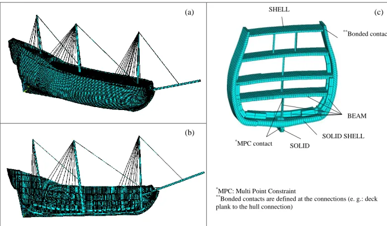
A full-scale model of the 17th century Vasa shipwreck has been developed to assess its current and future structural stability as well as design an improved support structure. A wireframe model, consisting of only lines, points and curves to describe the geometry of the ship, has been provided by the Vasa museum. It has been developed based on geodetic measurements using a total station. From this wireframe model, a three-dimensional (3D) model comprising solid bodies for solid-like parts (i.e. hull and keel), surfaces for the shell-like components (deck planks) and lines for beam-like constituents (deck beams) has been developed in Creo Parametric 3D software. This geometric model has been imported in finite-element software, Ansys, for further development of the stiffeners (knees, riders, stanchions, masts, etc.), adjustment of the correct location of deck beams and, finally, structural analyses of the entire ship (Figure 1). The procedure for selection of the different types of elements in the finite-element (FE) model, the definition of orthotropic material properties for the timber structure and preliminary results are discussed in this paper. Experiences drawn from this engineering project may also be useful in development of finite element models for structural assessment of other complex wooden structures in cultural heritage.
Figure 1: (a) The full-scale FE model of the Vasa ship; (b) a middle section of the ship model; (c) a longitudinal cross-section, showing different element types and connections.
During development of the FE model other similar historical shipwreck projects, in particular [1-3], have been used.
References
[1] Fenton R.F., Fowles R.J. HMS victory: modelling and structural analysis: how this contributes to the conservation of Nelson’s famous flagship. Historic Ships, 25-26 November 2014, London, UK.
[2] Invernizzi S., et al. Numerical modelling and assessment of the Ebe schooner-brig., International journal of Architectural Heritage: Conservation, Analysis and Restoration, 6:5, 453-477, 2012.
[3] Stoyanov S., Mason P.,Bailey C. Smeared shell modelling approach for structural analysis of heritage composite structures – An application to the Cutty Sark conservation. Computers and Structures 88 (2010) 649–663.
SOLID SHELL
*MPC: Multi Point Constraint **
Bonded contacts are defined at the connections (e. g.: deck plank to the hull connection)
SOLID BEAM SHELL ** Bonded contact * MPC contact (a) (c) (b)