, ~ -*.;,;:71-.."l. } 9-,» J: 513:9: ff s : 71' -f '0 " : 1"'3" i 7.'; p. " 71"???" 'h " - :3 r. . _
r . . I d '-.
- 4 C lV . I t l - . ' _ ' ' _r. '3 .. . 9 3 ,- . . 1 "1 ¢ ":1 ' j r. _ j A . " .
r
it
>
mm . Fa » .s-som link
~§w
~
~ ~ A " - -
A
y - ' .y, 'w >_ .'3 r ,. ' ' . . , ' _ ' r , . o 3 , V , , W k. '- I $.t, . 'u.. .t . 0': u (- n ' _ . . - r . a - V _ .- s . . V a _ _ U ;. a K. -_ ~ _ » .l . . I . ' o > J -- w. . . 1 r - . ~ . ' _. V - > . a ,9 I h _ ' . r_ _ k r . ,4. . . I 5 I " g I '~ I i AA . ' . -. I- - . . _, . ,. . I . . . "4 2 _ 1 1 ; . . A ~ v A - . " 4 ' p v ._ . t . i _ . g. v. ~ ~ ' v r .- '2 H I h ' . ' " " ' A . . | p ' C v | ' ' < I ' l y. . . . n . - a . . _ u . i I ' Ip \ ' O z , j n J n . n c ' __ .. . , .. | . . ' 5 ' . 4 l I . v I ' , . r at :4.4 - ~ v - ( v ' w, ' . U |_._ . ~.~-..- . I . a V IV 4' .9_ ' c I I N.i . 's- 71'» 1 - ' 1') .r . »_ . {O. I . , I ~ z -{a "'. "3-- ¢ . a I} J O 1 a. 1 "l. | ' ' u b. . C. i V 445 . M . h C 3"V v O ' I . ._. I-y' » . _ _ k l .7 . . 1 «.4. ~..._ , x -o .. a I J V i K . .. .9. d. 4 I! 2 u \ . . . . . I I ,m i . . . . l O . . u a I \ r 0 . . ' . 41 I l .-w 9 . v. 4 1 7 LA *5 . r.» -3. b [x l.\v o 4 v A v 4 y-«u.. A. - ~ .H . . .. r . ,A - , . . ., . I . > H i r > . I 7" ~:I . I ~ ' h " ' ' . ypvu ,u ' h: v I 'A . '' ' - I - . --> ~ J. x V ' ' . \ I . 4 V . .. n _ I. . . .a ~\4 . l . 1 ._ - ~ , . O, 0 ~ , , o :1 i ' . V i o .' ' «'61:; . ' 9':qu. ' I ¢ ' - - . > . ' " 0.. _ i ~ \ \Iu , - ' . w u o - ' . . " . _ k s a \ ~ . . a o, -' - .. , . p T _ I _ t V I . («-3 v _ -' v , r ~ on . v ' . K _ _ . . , z": 1. . '. _« ' . -' ¥ . _ ~. I V | " c w . _ . . l _ _ > _ , -1 _ - ' ' \ -, _ . G - . , . . r I , . , . . iv ~ ,1h . I .. V O v . I. . . ' . r. . e y I 1 .. ' . . - . I» I .l . : . ' . . n t . ., . y .. . . ' ' l '- ''6 c; I - x A . I, ~ 9' u a l i ' . ' . .. { ' 4 u . 0 ' . . . , a . . 4 _ _ in .'- V ' ' ~ ' a l, -. i ' . u - c . . ' ._ .w. - - t ( K u . . . . K ~ . " f .. 'n~ ,* - O . v I . r ' . 7' _ I ~ "1 .4 I, 5" 2. : ' ~ 4., . . z... ", w , - l . i , x rv . ' , \. . . ta. _ I . <4
Statens viig- och trafikinstitut (VTI) ' Fack - 581 01 Linkiiping
National Road & Traffic Research Institute - Fack - 5-581 01 Linkiiping - Sweden
100A
Nr 100A - 1977
Anti-Lock Braking System for
Passenger Cars Development of
a Brake System giving Yaw Stability
and Steerability during
Emergency Braking
by Giista Kullberg, Olle Nordstr m
PREFACE
The develOpment of the anti lock brake control system described in this report was initiated by the Transport Research Commission (TFK) of the Royal Swedish Academy of Engineering Sciences (IVA), especially should be
men-tioned its general secretary at that time Stig Samuelson
and the member of the road and vehicle committee of
TFK chief engineer Gosta Kullberg.
The project has been financed by the National Swedish
Board for Technical DevelOpment (STU), the National Swedish Road and Traffic Research Institute (VTI),
TRYGG-HANSA (Eighty Year Fund) and TFK.
Chief engineer Gosta Kullberg has been the project
mana-ger with chief engineer Olle Nordstrom as assistant.
Christoffer Bengtsson at the electronic company DELAB and Goran Palmkvist at VTI have been responsible for
construction and programming of the electronic system.
The technical division of VTI has made the mechanical parts of the wheel speed sensors and modified the hydrau
lic system. Hans Runqvist was responsible for the elec
tronic part of the wheel speed sensor.
The main principlesc fthe anti lock system have been
patented by Gosta Kullberg and Olle Nordstrom. Patents
are held in Sweden, the USA, the United Kingdom, France
and Italy. Patent has also been applied for in the
Federal Republic of Germany. The patent rights are held by VTI.
This report has been written by Olle Nordstrom with Goran Palmkvist as responsible for the description of the electronic controller. The project manager Gosta
Kullberg has contributed withadvice and instructions.
5.1 5.1.1 5.1.2 5.1.3 5.1.4 5.1.5 5.2 5.3 5.4 5.4.1 5.4.2 5.5 5.5.1 5.5.2 5.6 5.7 CONTENTS ABSTRACT SUMMARY INTRODUCTION
REASONS FOR THE INTRODUCTION OF ANTI-LOCK BRAKE SYSTEMS
QUALITIES OF DIFFERENT TYPES OF BRAKE SYSTEMS Conventional brake systems
Anti lock brake systems
THE STEERING AND BRAKING QUALITIES OF CAR TYRES
TECHNICAL DESCRIPTION OF THE SYSTEM
General description
Control system design
Controlled output
Reference Speed Free rolling logic
Reference wheel slip
System configuration
Wheel speed sensors Hydraulic system Brake system
Modulator valves
Electronic control unit
Logic control unit Interface unit Programming unit
Test vehicle
VTI REPORT NO. 100A
Page
m [1 L U M P N N N N N N N N N N H G N O N Q G O N O N O W O N O N Q O N W W W W N N N N I J W M H Page
TESTING
19
Laboratory tests 19Testing of the electronic control unit by 19
simulation 2
Testing of the complete system in the test vehicle 19
Field tests 20
Measuring equipment 20
Tests on ice with studded tyres 20
Test conditions 20
Method 21
Results 22
Tests on dry asphalt concrete 25
Test conditions 25
Method 25
Results 26
DISCUSSION AND CONCLUSIONS 27
Anti-lock brake system for passenger cars
- DevelOpment of a Brake System giving Yaw Stability
and Steerability during Emergency Braking
by Gosta Kullberg, Olle Nordstrom, Goran Palmkvist National Swedish Road and Traffic Research Institute Fack
8-581 01 LINKUPING SWEDEN
ABSTRACT
The report describes the develOpment of a so-called anti-lock braking system and the results from field tests with an experimental vehicle.
The purpose of the project has been to demonstrate in practice the possibilities to maintain steerability and
yaw stability during emergency braking in a curve. Furthermore, to create conditions for making necessary
investigations to support regulations concerning
anti lock systems, to build up technical know how
inde-pendent of industrial interests and to offer the
re-sults for the disposal of the industry. The rere-sults from tests made on ice and on dry asphalt concrete show that the anti lock system gives the experimental
vehicle good steerability and yaw stability during emergency braking in a curve. At the same time good
braking efficiency is maintained.
II
Anti-lock brake system for passenger cars
- Development of a Brake System giving Yaw Stability and Steerability during Emergency Braking
by Gosta Kullberg, Olle Nordstrom, Goran Palmkvist National Swedish Road and Traffic Research Institute Fack
8-581 01 LINKUPING SWEDEN
SUMMARY
A large number of accidents occur due to the drivers loss of control of his vehicle in connection with bra-king. In many cases it is evident from skid marks that
one or more wheels have been locked.
In the report No. 48 "Course stability of road vehic-les" published by the Swedish Transport Research Commis-sion (TFK) in 1960, it was shown howyaw stability and steerability is lost if wheel locking occurs during
braking.
At this time no commercially available anti-lock brake systems for cars were produced and existing prototypes were either very expensive or very primitive with
un-satisfactory performance. In consideration of the sub-stantial traffic safety effectthat could be expected from well functioning anti-lock systems in cars it was decided that the development of such a system should be financed by a governmental research fund. This system could be used for investigations concerning apprOpriate regulations for anti lock systems. The develOpment work would also build up expertise independent of industry on this type of brake system. Furthermore, results and experience gained could be used by the automotive indu
III
Therefore, in 1961 a working program for the
develOp-ment of an anti lock system for cars was started. The
main principle for the system control was to sense ro-tational wheel slip and to maintain a predetermined wheel slip as close as possible. Wheel slip is defined as a measure of the rotational speed of a wheel in re-lation to the free rolling speed of the wheel. In 1967 a brake control system was presented, installed in a passenger car with one unbraked rear wheel which was used to achieve a reference speed. In 1968 application for patent was made on a system with individual wheel slip control on all wheels with alternating brake re-lease on the rear wheels for reference speed
measure-ment. A brake control system according to this prin
ciple has then been develOped and tested in a passenger car on ice with studded tyres and on dry asphalt
con-crete with ordinary diagonal tyres. The brake tests on
ice were made from an initial speed of 50 km/h with a curve radius of 100 m and the asphalt tests were made from 75-80 km/h with a curve radius of 50 m.
The results can be summarized as follows
Brakeability m/s
Road Curve Speed Steer Yaw
Surface radius ability' stability V ii1 With wheel locked H1 km/h slip wheels
control
Dry Curve
asphalt
50
75
radius
Very
6 , 3
6 ,4
concrete can befollowed gOOd
Ice .
Studded 100 50 "- -"- 1,9 1,7
tyres
IV
The vehicle could be steered along the marked curve periphery both on the ice track and on the dry asphalt track. The initial speed on ice was equal to the limit speed for driving with constant speed. On the asphalt track the speed was so high that the curve radius could not be maintained at constant speed.
Yaw stability was very good under all testing condi-tions or with other words, no tendency to get a large side slip angle on the vehicle was found.
The braking efficiency with the control system active was always better on ice and lightly lower on dry asph-halt compared with locked wheel braking.
The reliability of the system has been good during the
limited number of tests that have been made. More work
remains before the system can be marketed.
Part of the aim of the project was the the system
should be able to be used as a means of research on ma king the basis for future regulations concerning anti-lock systems. The system now developed is judged to
fulfill that aim well, among other things, due to the
fact that it can easily reprogrammed. Furthermore, the project has provided the National SwediSh Road and Traffic Research Institute with valuable competence concerning anti-lock braking systems.
As examples of urgent research projects where the sys-tem can be used one can mention deeper studies of the ability of drivers to use the steerability during bra-king in different situations. Reliability is one of the most important demands on a braking system.
There-fore, long term tests under different conditions should
give valuable experiences concerning problems which may
occur with this type of braking system. The test vehicle,
then ought to be driven primarily by persons with
knowledge of the system. They have the greatest quali-fications to notice and interprete changes in the
sys-tem function that may occur.
INTRODUCTION
In the report No. 48 "Course stability of road vehic les" published by IVAzs Commission for Transport Re
search (TFK) in 1960, describing a survey and research work at the institution for vehicle technique at the
Royal Institute of Technology (KTH) under the manage
ment of Gosta Kullberg, chief engineer, it was shown how yaw stability and steerability are lost if wheel
locking occurs during braking.
ZH:thistime anti lock brake systems were used in some aerOplanes and trains. Regarding cars, ideas of anti lock brakes had been described in literature as early
as in the 1930's, and in some cases prototypes had been develOped. The main principle of those prototypes was the control of the deceleration of the wheel rather
than of the speed or the slip of the wheel. Test results showed a very incomplete picture of the problems which, so far, had prevented the develOpment of systems that could be commercially exploited by the car industry.
Bearing in mind the apparent advantages from traffic
safety point of View which the anti-lock brake systems
would offer it was considered justified to use govern-mental money in order to increase the knowledge in this field and to demonstrate, in practice, the advan-tages which could be attained theoretically.
This knowledge would perhaps increase the prospects of industry to realize systems suitable for series produc
tion and serve as a basis for governmental regulations regarding the performances of anti lock brake systems.
Technical knowledge within the country, independent of
industry, was also judged to be of value in assisting the governmental authorities regarding questions in
dispute within this domain.
On the basis of experimental and theoretical knowledge previously acquired, a system control towards a specific
wheel slip was estimated to give the best safety against wheel locking and, consequently, against lost
steera-bility and yaw stasteera-bility.
Systems working with this principle of control could not possibly be obtained from any manufacturer.
Conse-quently, it was necessary to develOp a system.
In 1961 a working program was presented concerning the
develOpment of an anti lock system with the aim to
maintain a constant predetermined wheel slip when
sen-sing rotational wheel slip. The work was financed by
the Commission for TranSport Research, the Swedish
Technical Research Council and The Fylgia 80 years fund. The develOpment work was then carried out till 1967 at the Institution for vehicle technique of the Royal Institute of Technology and to some extent in COOpera-tion with the NaCOOpera-tional Road Research Institute. In the autumn of 1967 the first prototype was presented for the press and for various authorities. The demonstration aroused a great interest and contributed to the decision of the National Road Safety Office, i.e., the preambule that regulations were to be expected in 1975.
The anti-lock brake system in the demonstrated
proto-type had several drawbacks, however. Only three wheels
were braked while the fourth was used to achieve the
reference Speed. This caused significantly lengthened
braking distances especially when the vehicle was loa-ded. The rotational wheel speed sensors had a low re solution and the control valves had a relatively slow reaction. The last mentioned circumstances caused great
variations in wheel slip and, due to this, a jerking
PrOpositions for the improvement of the system were
drawn by Gosta Kullberg, chief engineer, and Olle
Nordstrom, at present chief engineer at the National Road and Traffic Research Institute, and the applica tion for a patent was due in 1968, the National Road and Traffic Research Institute being the holder of the patent. In the same year the IVA Commission for Tran Sport Research applied to the Swedish Board for Techni-cal DevelOpment regarding the develOpment of an experi-mental system according to the patent specification.
Financial means have since that year been granted twice by the Swedish Board for Technical DevelOpment, and the National Road and Traffic Research Institute as well as the Commission for Transport Research have suppor-ted the project economically. The develOpment work up to the now finished system has been executed in COOpe ration between the project manager, chief engineer Kullberg, the National Road and Traffic Research Insti tute and the electronics company DELAB.
REASONS FOR THE INTRODUCTION OF ANTI-LOCK BRAKE SYSTEMS
According to a statistical investigation of accidents carried out within the Swedish ESV project "Steerabi-lity during Emergency Braking", the accidents caused by locked wheel braking are 10 15 per cent of all the accidents. Out of these 4-7 per cent could have been avoided if the steerability had been intact during braking. With the wheels locked the steerability is lost and the yaw stability as well, and consequently, the vehicle is easily brought into rotation under the influence of irregular road friction.
Examples of situations where locked wheel braking is
the cause of the accident are:
l. Braking in a left-hand curve where the vehicle goes straight ahead possibly under rotation and
goes off the road giving rise to overturning, collisions with trees, poles, rocks etc.
2. Braking in a right-hand curve where the vehicle goes straight ahead possibly under rotation and gets into collision with approaching traffic in the Opposite direction or goes off the road on
the left-hand side.
3. Braking on a straight road with lateral
inclina-tion where the vehicle slides off the road.
4. Braking in front of emerging obstacles where the vehicle goes straight ahead and gets into a colli sion despite of an attempt to steer off. If the steering wheel movement is performed with the wheels locked and if the brakes are then released
while the vehicle is still in motion the suddenly
returning steering action might surprise the driver and take the vehicle off the road before he has
time to make the necessary steering wheel
correc-tion.
A situation equivalent to that of an emerging obstacle
is when a car just in front suddenly brakes, or when a
car drives out into an intersection causing the risk of collision, i.e., by stOpping in the intersection.
A great part of the accidents with locked wheels in Sweden occur under winter conditions. This is why it is very importanttjm :the so-called anti lock brake systems also work under those conditions.
QUALITIES OF DIFFERENT TYPES OF BRAKE SYSTEMS
Conventional brake systems
A common characteristic of conventional brake systems
is that the brake tOEque is, on the whole proportional to the force applied to the brake pedal. If this torque exceeds the torque produced by the friction force bet
ween tyre and road surface the wheel will be locked and,
consequently, the steerability will be lost.
A locking of the rear wheels before the front wheels
leads to an instability likely to get the vehicle into rotation. This risk can be eliminated by a fixed distri-bution of the brake torque for front and rear wheels making the front wheels lock first at all occurring
decelerations and load conditions. This, however,
gives low braking efficiency at low friction. In order
to solve this problem, pressure reducing valves con-trolled by the brake pressure level, the deceleration or the load, or combinations of those quantities have
been introduced on the rear brakes by some car manu-facturers. This is one way of eliminating locking of the rear wheel brakes on a high friction surface. At
low friction levels the locking problem remains for
both front and rear wheels.
Anti-lock brake systems
In order to solve the problem of wheel locking
so-called anti-lock brake systems, have to be used. The main characteristic of those systems is the control of the brake fluid pressure allowing the wheels to
keep rolling with an efficient use of the available friction and at the same time making it possible to
steer the vehicle with a good yaw stability, i.e., with no tendency to rotational skidding.
Since quite a long time anti-lock brake systems have
been used on aerOplanes and trains where the profit
from the reduced wear Of the wheels has been significant,
ant the Operational conditions have been very well con-trolled.
Regarding road vehicles the develOpment has been slo-wer mainly because Of higher demands for low
manufactu-ring costs and more varying Operational conditions.
Anti lock brake systems are commercially available for
airbraked VehiCleS in the US thanks to the new braking
regulation FMVSS 121. Some Of these systems have, how-ever, been unsatisfactory as regards the Operational
reliability causing exemption for some time, awaiting the solution of those defects.
Regarding private cars there are quite a few systems develOped some Of which have been tested within the SCOpe of the Swedish ESV project, and at those tests they showed good performances. Till now anti-lock systems are only available on a few American luxury cars and these are quite primitive. This can be ex plained by relatively high cost, reliability problems
and Of course by the lack of performance regulations that make such systems necessary.
High performance systems must be produced in large
se-ries in order to have a reasonably low manufacturing
price. Rising costs on raw materials and personnel costs
have caused rapidly increasing car prices. The adverti
sing value Of a more effective brake system has appa-rently, until now, not compensated the rise Of prices
required. The large investment caused by such a radical
technical change is also likely to have contributed to the indecision Of industry to introduce these systems.
Regulations are Often looked upon as the only
THE STEERING AND BRAKING QUALITIES OF CAR TYRES
To allow the transmission of braking forces from a
car tyre, the tyre must be deformed and there has to be a sliding motion in the contact area between tyre and road surface. These motions are usually described with a measure called wheel slip, defined as
where v0==the velocity of the wheel center, and v== the circumferential velocity calculated from the
angu-lar velocity of the wheel and the roll radius. Wheel slip is usually expressed in per cent. The braking
force is usually described as a function of wheel slip. A steep rise becoming more level within the range of
10 30 per cents jg>is characteristicc fthis function. Within the interval of 30-100 per cent the course may be horizontal, falling or somewhat rising. The function is not only influenced by the road surface but also by lateral forces acting simultaneously, wheel load, speed
and tyre pressure.
Similar conditions are valid for the transmission of
steering forces from a car tyre. The lateral force
per-pendicular to the wheel plane is described as a func
tion of the angle between the wheel plane and the
cour-se of the wheel centre. This angle is called the slip angle (in German: Schraglaufwinkel, in French" angle de
derive). As was the case with the braking force
func-tion the lateral force funcfunc-tion is influenced by the
wheel load, the speed, and the tyre pressure and also
by braking forces acting simultaneously. The last men-tioned condition means that the lateral force at a cer tain slip angle may be described as a function of wheel
slip.
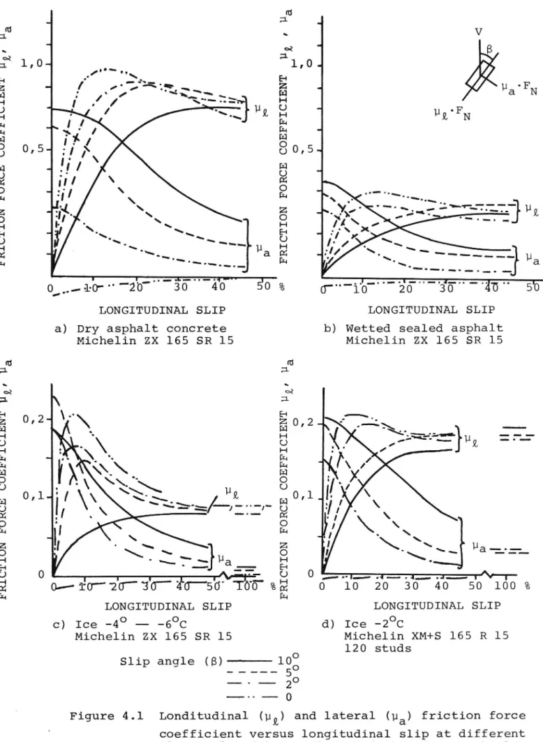
The figures 4.la c show the braking and lateral forces,
of an ordinary radial tyre for passenger cars, as a
function of wheel slip at various slip angles on dry
asphalt concrete, wetted sealed asphalt, and ice. Fi-gure 4.ld shows the same functions of a studded radial
winter tyre on ice. The diagrams in figure 4.1 are taken from the Swedish ESV Report "Steerability During Emer-gency Braking".
Leaving the various friction levels out of account the
curves appear, in principle, to be very similar in na-ture. The lateral force is reduced when there is an increase in wheel slip and at the same time the braking force increases to a maximum value. This maximum value ranging between 10 and 30 per cent of the wheel slip
interval, the slip angle being zero, is deplaced towards
a higher wheel slip value at an increase in the slip
angle and, simultaneously, the force is reduced.
The lateral force is reduced at an increase in the wheel slip, quite slowly at very low wheel slip values and decreasing more rapidly thereafter. At a wheel slip of about 50 per cent the curve becomesrmmxelevellmnzthe
lateral force is then insignificant.
Wheel brake control with the aim to obtain the best deceleration possible will during hard cornering lead to wheel locking and lost ability of negotiating the curve. The system control towards a fixed wheel slip value will cause a decrease in the deceleration when cornering and the larger the slip angle or the stee-ring force respectively, the more apparent the decrease.
The decrease can, however, be kept reasonably small
and the deceleration is normally larger than with locked
The steering force required decreases normally, however, rapidly with speed. Due to this fact, the reduction of maximum steering force required to obtain a good bra-king efficiency ought to be acceptable.
Such a system control is likely to give an almost Opti mal braking efficiency at low steering forces and at the same time a good steerability is obtained, when
required, giving a moderate reduction of the decelera
tion.
TECHNICAL DESCRIPTION OF THE SYSTEM
General description
§9§E£9l_§y§fsm_§§§29§
The control system is based on a simple Opening or
closing of solenoid modulator valves resulting in an
increase or a decrease of the brake pressure dependent on the controlled output being larger or smaller than the reference input. Each wheel is controlled indivi-dually.
992§£9ll§§_99§222
Wheel slip is used as controlled output in the control system and is calculated from the rotational velocity of the individual wheel and a reference speed.
B§£§£s92§_§ess§
The reference Speed is obtained intermittently from the left and the right rear wheel in sequence. The
speed is measured after the wheel brake has been
10
sed the led
the
and the wheel regained "free rolling" speed. After measurement the wheel is braked again and control
like the other wheels. Between each measurement reference velocity may be
1) Constant
2) Stepwise decreasing with stepsize and step interval
determined by the difference between the last
mea-sured value and the proceeding one and a nominal updating time interval
When driving without braking the reference speed is
measured without activating the modulator valve to the
measuring wheel in question. When braking, the valve
is not activated, in order to release the rear wheel
in question, until a too large wheel slip has been mea-sured on one of the wheels. This implies that the re-ference speed is somewhat too low at the beginning of
the control.
The updating frequency is however high enough to
en-sure that this is of no importance in practice. When
the reference Speed becomes lower than a certain value (810 km/h)
do in this situation give good deceleration and the the control is disengaged. Locked wheels
added system complexity required to achieve efficient control at this low speed has not been regarded as justified.
E£s§_£9lli99_legis
When a reference speed value has been obtained from
one rear wheel a clock is started in the control unit.
After the time T1
which until now has been braked is actiVated in order
After the time T2 which takes into account the time necessary for the brake to be
the modulator valve to the rear wheel
ll
surely released a comparison is started between a reference acceleration and the acceleration of the
wheel. When the acceleration of the wheel has been redu-ced below the reference acceleration the wheel is consi-dered as having obtained free rolling velocity. The
speed is then measured and introduced as a new reference speed. After the measurement the modulator valve com
mand is returned to normal which means that the Wheel
is braked again. The acceleration check requires a certain minimum time T3. The minimum time between the updating of the reference velocity will thus be Tl-+T2-+
T3. T3
in wheel speed must not pass a predetermined value. If
is a fixed time interval during which the change
this is passed within the time T3 the time count
re-starts from zero.
B§£§£s292_wh§§l_§lle
The reference value for the wheel slip is chosen so
that the real average wheel slip stays within an inter
val where the braking efficiency is equal to or better than the braking efficiency with locked wheels on a
surface having a friction coefficient for locked wheels
which is lower than the maximum one.
Furthermore, the relation between the reference wheel
slip values for front and rear wheels is chosen to maintain a good directional stability and a good stee~
rability.
Due to the intermittent release of the rear wheels
for the measurement of the reference speed a conside-rably higher reference slip value than the desired
has to be average wheel slip value, for these wheels,
chosen.
12
The reference wheel slip values have been determined from field tests on ice and asphalt concrete.
The Optimal relations of the front and rear wheel slip values are dependent of the vehicle. Thus, it is possib-le to give a higher wheel slip value to the rear wheels of an understeered car than it is to the rear wheels of
an oversteered one.
§ystem configuration
The anti lock brake system consists of three principal systems (See Fig 5.1)
1. Wheel Speed sensors 2. Hydraulic system
3. Electronic control unit
There are four wheel speed sensors of optical type, one for each wheel, placed in the disc brakes. They give 120 pulses per wheel revolution. The pulses are transformed to square pulses in a special electronic unit. The hydraulic system comprises on the one hand a braking system of full power type, made by Citroen, on the other hand four two-stage tree way solenoid valves Operated by the electronic control unit.
The electronic control unit is completely digitalized
and contains a micro computer.
In order to facilitate the field tests the micro com-puter has been made easily programmable by means of a manual programming unit. To be able to test the system
without driving the vehicle a unit for the generation
of simulated wheel pulse signals is included. Further-more, power amplifiers are used for activating the
13
Wheel speed sensors
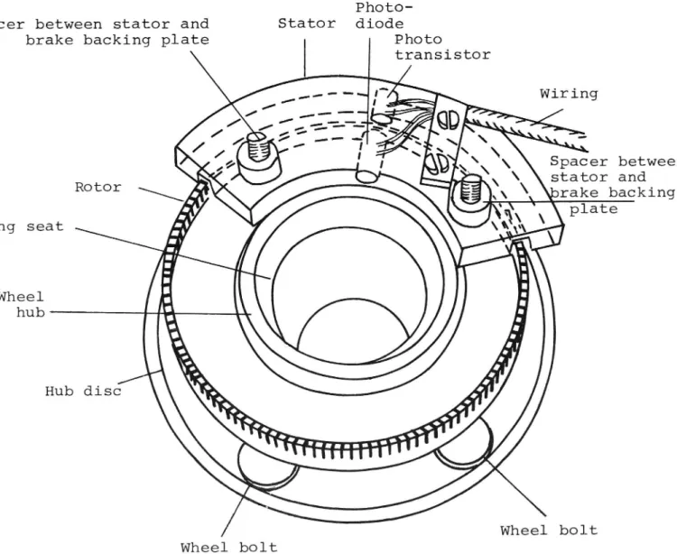
The wheel speed sensors have been constructed at the National Road and Traffic Research Institute and have been described in the internal report No. 64 "A sensor
for accurate measurement of angular velocity or angular
velocity change of a car wheel", 1972.
The wheel speed sensors comprise two units
1. Stator
2. Rotor
The stator is made of bakelized fabric. It has a circu lar slot, 5 mm in width and 10 mm in depth. On the in-side and the outin-side radius respectively of this slot two radial holes end, having the same centre line.
A light emitting diod, LED, has been placed within the
inner hole and the outer hole comprises a phototran-sistor. They are both of them imbedded in clear epoxy plastics. See also Fig 5.2. The stator is fastened by two spacers on the brake backing plate.
The rotor is made of aluminium formed like a cylinder, with walls 3 mm in gauge and 2 cm in width. The diameter is approximately 160 mm. On one side l20 axial slots have been cut out. The rotor is fastened to the wheel hub. See also Fig 5.2.
In order to supply the sensors with power and to trans form the sensor signals to square pulses of a well defined form a special electronic unit has been built, supplied from the car battery. From this unit the modi fied sensor signals are transmitted to the electronic
control unit.
The electronic system has been described in its
origi-nal version in the interorigi-nal report No. 64, published by
14
the National Road and Traffic Research Institute, but
has been slightly modified after the publication of
this report.
Hydraulic system
§£§E§_§Y§E§E
The vehicle, a Volvo 144 from 1967, is originally
equipped with disc brakes on all the wheels. In order
to reduce the risk of rear wheel locking it is provided
with control valves activated by the brake fluid pres-sure which changes the brake force distribution. The system is equipped with a servo assistance of vacuum type in order to obtain low brake pedal forces. Further more, the system is based on two hydraulic circuits where each circuit affects the two front wheels and a
rear wheel.
The following modifications have been carried out.
1. The vacuum servo has been put out of Operation and
the ordinary master cylinder has been replaced by
a master cylinder from a Citroen ID 20.
2. The following details have been taken from the same type of Citroen
oil pump
pressure accumulator
oil tank
3. The two circuit system has been altered in such a way that, the front brakes are accomodated by one circuit and the rear brakes by the other.
The configuration of the brake system is shown in Fig
5.3. In normal use of the reconstructed brake system
L. A
he master brake cylinder (C
('
l' l and C2) works as a
.4.
15
pressure reduction valve betweenthe pressure
accumula-tor (A) and the wheel brake cylinders (Bl-B4). The degree of pressure reduction is decided by the force
of the brake pedal. Each time the brakes are applied
there is a certain tIanSport of oil from the pressu re accumulator through the master cylinder (reduction
valve) to the wheel brake cylinder at an increase of
the pressure. At a decrease of pressure the hydraulic
oil is diverted from the wheel cylinders, through the
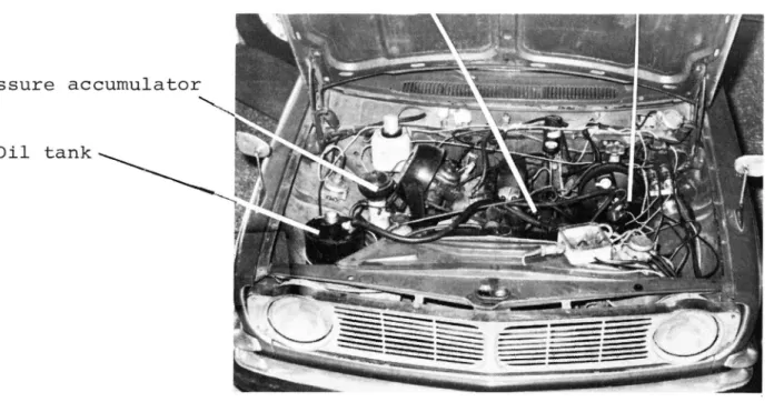
reduction valve, into a return piping to the hydraulic oil tank. The locations of the system components in the engine are shown in Fig 5.4.
¥9§2l§29£_22lys§
An electrically Operated valve is positioned between
the master cylinder and each wheel brake (see Figure
5.5) in order to allow the electronic control unit to modulate the brake force. The valves, of solenoid type and with a two stage function, have been designed by Saab-Scania to fit an anti lock system develOped by this company. When not activated, the valve has a free passage from the master cylinder to the wheel cylinder. When activated this passage in the valve is locked and the wheel cylinder is connected to the hydraulic tank instead and, thus, becomes depressurized. The location
of the valves is shown in Figure 5.5.
For every on-off cycle of the valve a certain oil transport takes place from the accumulator to the hydraulic tank. The large number of valve actuations during a continous control leads to a significantly larger oil flow than is the case at normal braking.
There are however no problems regarding capacity as long as the oil pump is in action, i.e., the engine
works.
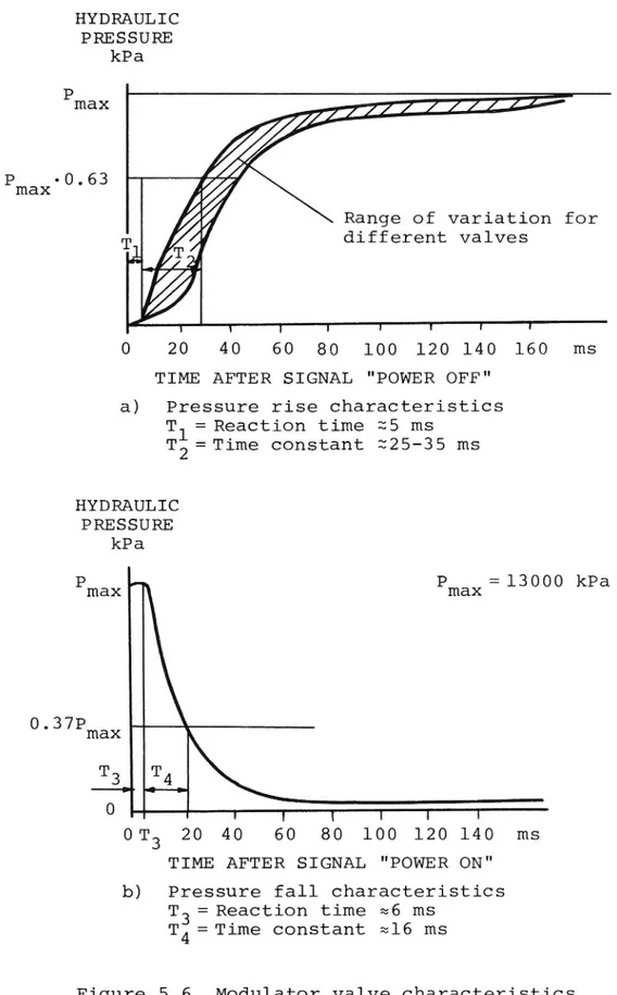
16
The following data are valid for the valves which have been modified by the National Road and Traffic Research
Institute:
12 volt
48 watt per valve at a continous duty
Supply voltage:
Power required:
Reaction time when activated (decrease of pressure)
z 5 ms (Figure 5.6.a)
Reaction time when deactivated (increase of pressure)
3 5 ms (Figure 5.6.b) Rise Time
x 25-35 ms
Fall Time (Time to obtain 37% of the initial pressure) (Time to obtain 63% of the terminal pressure)
a 16 ms (Figure 5.6.a)
Electronic control unit
£99l§_2922£91_2ei2
The logic control unit consists of a micro computer system built from a parallell CPU of 8 bits, mark INTEL 8080, as a base. (CPU==central processor unit).
(PROM) and (PROM==Program read only
The system includes a number of read read/write (RAM) memories.
memory, RAM==Random access memory). Besides, it com-prises an unit towards external functions and a control
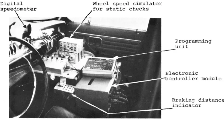
logic unit in order to synchronize the different units. In order to facilitate any modifications that may occur during the development phase a programming unit is also part of the system. The configuration of the system is shown in Figure 5.7. Figure 5.8 shows the electronic control unit mounted in the test vehicle.
From the CPU list of instructions comprising 74 differ-ent instructions the sequence of instructions required for the operation of the control sequence has been produced. The instructions have been programmed in a
l7
PROM and are the so-called program or software of the system. Each instruction consists of 1-3 words contain-ing 8 bits. The program comprises approximately 1000 words. The computer has a capacity of addressing 256 inputs/outputs. In our case 13 inputs and 6 outputs
are used. The program could essentially be described
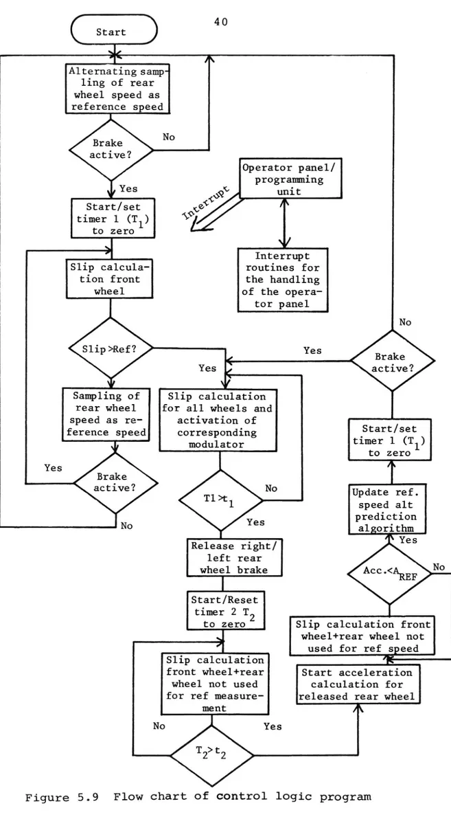
according to the flow chart in Figure 5.9.
As the construction is a prototype the system has been completed with a programming unit + extra read/write
memory facilitating the modification of the program
during the test work. See more complete description
below.
Interface unit
The external functions like power amplifiers, valve control, wheel pulse sensors, and braking status (bra
king light on/off)
via an interface unit. The interface unit comprises
communicate with the computer unit
required logic units and noise elimination circuits.
Optical couping devices are among other things used
for noise elimination.
The angular velocity of each wheel is obtained by
measuring the time between two adjoining wheel pulses
(120 pulses/turn). The time measurement is executed
by counting the number of pulses from a reference
oscillator. The time (the number of pulses) is stored
in buffer registers and is a measure of the momentary
angular velocity of the wheel in a digitized form. When the wheel pulses arrive asynchronously the input to the computer is adapted to the clock pulses by a number of synchronous networks.
Each time a new" speed is available in the buffer
registers a bit is put in a so called status word which
18
is gathered to the CPU continously and which is deco-ded in the program. The status word also contains
in-formation on the braking status and the state of the three time meters Tl, T2, T3 (see section 5.1.4).
The program generates a control word which is stored in a register from which among other things the power
amplifiers of the solenoid valves are controlled.
Programming unit
As was mentioned previously in the text it has been
regarded as very important to be able to modify the program during the test phase. As the basic program is normally stored in a read (PROM) memory which is not
available for writing, the program is copied to a read/write memory each time the system is energized. An external Operational unit makes it possible to
write/read instructions to/from memory addresses called
by the operator. It is now possible to modify the
program, write test programs etc. Addresses and
instruc-tions are programmed in a binary code switch by means of a
set of manual switches (see Figure 5.8.).
When the Operator calls for a sequence from the
programming unit an interrupt is generated
interrupt-ing the normal execution of the program. A special section of the program administrates the interrupt routines.
The program modifications which have turned out to be suitable are read in on the PROM via a special program-ing equipment which also erases the previous contents.
l9
Test vehicle
The test vehicle is a Volvo 144. The car was made in
1967 and is an early series Volvo test vehicle bought from Volvo.
TESTING
Laboratory tests
T§§EEES_9§_EEE_EEEEE£9§EE_EQEE£9£_EEEE_§X_§ETEEEEEQE
A simulator with wheel pulse generators was deve10ped in order to facilitate the testing of the electronic control independently of the vehicle. With this device the proper function of the different program steps of
the control logic was checked.
Is§2329_9§_§hs-29@2l92§_§y§2sm_22_29s-Es§E_Yshisls
Having proved that the electronic control unit worked according to the program it was mounted in the test vehicle. The vehicle was then tested on a roller type brake tester at various constant speeds.
The results were recorded on a memory oscilloscope and photographed. At those tests the wheel speed, the
brake fluid pressure, and the control signals to the
modulator valves were recorded.
The tests showed that the system worked satisfactorily.
20
Field tests
M§§§E£iag_eggiemeaz
The following measuring equipment was used in the field
tests
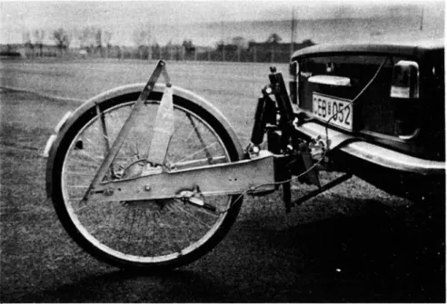
1. Measuring wheel for the measurement of vehicle speed and braking distance, see Figure 6.1.
Marking gun for the marking with colour shots on the road surface at the beginning of the braking. Electrical operation from the brake light, see
Figure 6.2.
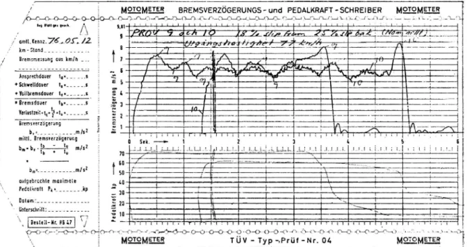
A mechanical decelerometer of the make "Motometer", see Figure 6.3.
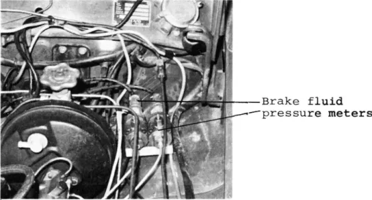
Two brake fluid pressure meters of strain gauge type used on one front and one rear wheel (made by Bofors, see Figure 6.4).
5. A memory oscillosc0pe for the registration of a. the brake fluid pressure of one wheel
b. the wheel velocity of two wheels
c. control signals to the solenoid valves of those wheels
d. the speed of the fifth wheel Thus,
tion was registrated by the Motometer device on a
se-in all 6 variables, see Figure 6.5. The decelera
parate sheet, see Figure 6.6.
Ie§2§_92_i§§_wifh_§fgééeé_22£§§ Test conditions
The tests were carried out on an ice track on the lake
of Orsa. The air temperature varied from l to ~6OC and the sky was clear. The vehicle was tested in a
6.2.2.2
21
load condition similar to the weight of the driver plus a passenger in the rear seat. Studded radial
tyres, 165 SR 15 of the mark Semperit, were used. The
number of studs per tyre were about 120 with a projec tion over the surrounding tread of l-l,5 mm. The front tyre pressure was 180 kPa and the rear tyre pressure was 220 kPa. The tyres were completely new and had
only been driven for some kilometers on aSphalt concrete.
Method
The tests were carried out in accordance with the
method prOposed within the Swedish ESV project. Accord-ing to this test procedure the steerAccord-ing wheel deflec-tion for the maximum lateral acceleradeflec-tion at a certain speed is determined. Thereafter the vehicle is
acce-lerated up to this speed and then full brake pedal
force is applied at the same time as the steering
wheel is turned to the angle which had been determined previously. The braking distance and the lateral devia-tion from the course at the moment of applying the
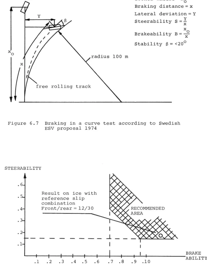
brakes as well as the side slip angle of the fifth wheel or equivalent values are measured. The quotient of the lateral deviation and the braking distance is
used as a measure of steerability (see Figure 6.7).
The maximum side slip angle is used as a measure of yawst-ability.20O at the maximum is accepted. The tests with locked wheels are carried out at the same initial
speed as the one which was used in the curve tests. The relation between the braking distances is a measure of the brakeability.
On the basis of the test results of the Swedish ESV project the steerability and the brakeability were suggested to be held within certain limits in accord-ance with Figure 6.8.
6.2.2.3
22
The tests were carried out during two days and 56 tests in all were performed. The first day a large number of
studs on one of the tyres fell off giving rise to un-symmetrical brake efficiency. The steerability test was
influenced to such an extent that the test results have been considered of no use in a comparison with the ESV requirements. Four new tyres of radial winter type were supplied and were used the following day. The number of 4 with manual steering in
The test
tests the second day were 32;
order to obtain the best steering results.
speed at the beginning of the braking was 50 km/h throughout these tests. Owing to damage to the side slip angle meter this quantity was only estimated du ring the measurements of the second day.
Observations made at previous tests regarding side
slip angle measurement have shown that even a side slip angle of 70 is regarded as a beginning skid mo-tion by the driver. At the tests in quesmo-tion no such skid tendencies were experienced.
Results
An example of a typical control process for a front wheel and a rear wheel is shown in Figure 6.9.
EEEEELEEY
At all the reference slip combinations tested the car was stable and the side slip angle was below 100 when measured. The side slip angle meter broke down during
the tests in the beginning of the series and could not
be repaired at once why measuring values are missing for the majority of the tests. From a subjective esti-mate, however, the side slip angle was from stability point of view always neglectable.
23
Independent of the prOper test program brakings were performed from 90 km/h having a very good efficiency and stability from a subjective estimate. One test was also performed where the car was braked with the
anti lock sysban after due to a too high curve speed
the car was brought into skidding of a side slip angle of approximately 200. The car was immediately stabili-zed by the braking and regained easily the desired
course .
§§ssrséili§y
The following results were obtained for the
steerabili-ty S defined as S==§ where y==side lateral deviation
from the track tangent at the beginning of the braking
and x==the braking distance.
Reference wheel slip . .
front wheel Steerability S
Reference wheel slip Number Mean Standard
rear wheel of tests value deviation 12/25 7 0.13 0.015 12/30 3 0.17 0.012 17/25 8 0.085 0.007 17/30 4 0.078 0.021 25/25 3 0.033 0.003
At an exact following of the free rolling radius for
the speed in question (50 km/h), and with the decele-ration the steerability value is S==0.13. This radius
was followed very precisely with a reference front
wheel slip of 12% and a reference rear wheel slip of 25%. At a reference front wheel slip of 12% and a re-ference rear wheel slip of 30% the steerability (S) increased to 0,1710,012 without influencing the mean deceleration. At the last mentioned configuration the
car was thus less understeered.
24
In the Swedish report "Steerability during emergency braking" the minimum value S==O,lS has been suggested. This value is reached for the wheel slip combination
12/30. However, tests with manual steering without
Special steering wheel angle limitations showed that the marked free rolling curve radius of 100 m could be
followed at all reference wheel slip combinations without
great difficulty.
The required steering wheel angle was less than 1800 in all cases. The steering wheel angle at the tests with a fixed steering wheel angle was approximately
600. The results are shown in the form of a diagram in Figure 6.10.
Concerning the reference slip of the rear wheels it should be kept in mind that due to the free rolling cycles of these wheels the real mean slip is only about half the reference slip, see also Figure 6.9.
Braksabilify
The mean value and the standard deviation for the mean deceleration calculated from the initial speed and the
braking distance are shown in Figure 6.11 on the one
hand for locked wheel braking and on the other hand for braking with the anti lock system in a radius of 100 m. The initial speed in both cases was about 50 km/h.
The figure shows that the mean decelerations at braking
with the anti lock systems for all combinations of re-ference wheel slip have been higher than at locked wheel
braking.
Mean values:
H-Anti lock brake system aa==l.93 m/s2
6.2.3.2
25
Equivalent braking distance from 50 km/h
Anti-lock brake system 50.8 m
Locked wheels 56.6 m a
The ratio ~3==l.12
aL
According to the limit values prOposed by the Swedish a
ESV project group 52 exceeding 0,7 should be accepted.
L
Thus, this requirement has been fulfilled by a large
margin.
I§§E§_99_§£2_§§9h§l2_ssas£e2e Test conditions
The tests were carried out on a dry horizontal track of aSphalt concrete at the National Road and Traffic Research Institute in Linkoping. The air temperature was about 200C. The weather was characterized by changing cloudiness. The test car was equipped with
diagonal tyres, mark Goodyear G8 6.00 15. Tyre pressure:
front 170, rear 220 kPa.
measuring equipment plus driver equivalent to service
The Vehicle was loaded with
weight plus one passenger in the rear seat.
Method
The tests were carried out with an initial Speed of between 75-80 km/h, normally about 77 km/h. The test speed was at maximum regarding the dimensions of the track and the acceleration resources of the car.
Tests were carried out partly on a straight track, parly in a curve having av inner radius of 50 m and a track width of 3 m. At 77 km/h this was equivalent to
6.2.3.3
26
7 m/s2 is regarding tyres and car construction the maximum at
a lateral acceleration of approximately 9 m/s2
a constant speed. Figure 6.13 shows the test car after
the braking in a turn test.
At the braking in a turn tests steering and braking were started approximately simultaneously. The engine was declutched before the brakes were applied. Only one reference wheel slip combination was tested. The reference front wheel slip was 18% and the reference rear wheel slip 25%. On the other hand three reference speed systems were tested.
1. Without prediction based upon the previously measu-red reference speed value
2. With prediction based upon the previously measured
reference speed value
3. With prediction based upon the previously measured reference speed value and a lower speed at the dis
engaging than at the engaging of the control system.
Results
Figure 6.14 shows the typical registrations. The tests
showed that the car could be steered through the curve
during braking. The required steering wheel deflection was between 900 and 1000 in the first part of the curve but had to be diminished in the latter part in order to prevent the car from steering off the track on the inside of the curve. The Ackerman steer angle at the steering wheel was 600 for a 50 m radius turn. 1800 is equivalent to a difference in side slip angle of appro-ximately 60 between front wheels and rear wheels.
27
The mean decelerations in the braking in a turn tests
were:
combination 1 (2 tests) 5.56 m/s2 combination 2 (3 tests) 6.07 m/s2
combination 3 (4 tests) 6.35 m/s2
At the tests on a straight course the following mean
decelerations were obtained:
combination 2 (4 tests) 6.03 m/s2
locked wheels (2 tests) 6.36 m/s2 (6.38 and 6.34 m/s2)
When the results are expressed in braking distances starting from 80 km/h the following values are obtain-ed: 6.36 m/sz==38.8 m (locked wheels)
6.35 m/s2==38.9 m
6.07 m/s2==40.6 m
6.03 m/sz==40.9 m
5.56 m/s2==44.4 m
During braking in a turn the car was understeered in
all the tests runs and had a very good yaw stability.
The understeering index was between 30 and 60, i.e., the front wheel steering angle was 30 60 larger than the Ackerman steering angle.
DISCUSSION AND CONCLUSIONS
The tests on ice have shown that the anti lock brake system fulfills the basic demands for stability,
steerability, andbrakeability by a large margin.
Compared with some of the systems which have been
tested within the ESV project, one characteristic fea-ture is the absence of stability problems. It should
28
be noted, though, that up to now the tests have only been carried out with studded tyres in controlled con-ditions. Tests with unstudded tyres on packed snow have been carried out, indicating that the system also works at friction levels lower than zO.2, but systematical measurements must be performed before any definite observations can be made. The tests were carried out with the simplest type of reference speed where the reference speed is kept constant between the values at free rolling. With the improved calculation of the reference Speed which has been introduced, since then, and which has been tested on high friction surfaces with satisfactory results there is no reason to believe
that worse results will be obtained on icy surfaces.
Better results could be questioned if they are physi-cally possible to produce as the values obtained up to now hardly leaves anything more to be desired.
The tests have only been carried out at a load
condi-tion just between service weight and gross weight. Considering the very good stability, the changes in position of the centre of gravity that can be eXpected are not likely to be critical to the stability. When studying the performance more closely all load condi~
tions should, of course, be tested.
The tests on dry asphalt concrete have shown that the
system gives an insignificantly lower deceleration on
this surface than is the case with locked wheels. At the same timei macar can be steered with a good
stability along a radius smaller than the radius which the vehicle should have managed at an undiminished Speed. The last mentioned performance is eXplained by the rapid decrease in speed but still demonstrates that there are relatively good prospects of correcting
a too high initial speed by braking if the vehicle is
29
Potential technical develOpment
The experimental system which now has been constructed
fulfills well enough in our Opinion the necessary de-mands on performance of an anti lock brake system regar
ding stability, steerability, and brakeability. There
do exist possibilities of further improvements of the system by introducing a higher wheel slip control limit in the lowest speed area (<10 km/h) instead of disconnec tion of the system. Such a change could theoretically give steerability combined with a good braking effici-ency down to the speed zero.
The flow resistance in the valve systems could
proba-bly be adjusted in order to obtain smaller pressure variations without decreasing the effectiveness of the
system which would increase the braking comfort and decrease the mechanical stress on the vehicle. Damping and elasticity in the wheel suspension eSpecially with reSpect to torsion is theoretically of importance to the function of the anti-lock brake system. Tests for the experimental verification of theoretical analysis and elaboration of specified instructions to the car manufacturer should be a component in a continued de-velOpment work.
The fail safe functions need to be studied further
and they must probablybe completed.
The dimension of and the production cost of the
elec-tronics could be diminished by an increased integration
in specially adapted units so that the electronics
neither as regards space nor costs would be a critical part of the system. The tendency among the manufactu
rers of present anti-lock systems is a change-over from
analogue to digital systems. The differences between
various systems should functionally be the logic
con-structions. The dimensions should not differ if the same
3O
integration technique was used. The price seems to be a function of the number of units that are produced due to high initial costs at the develOpment of the
production apparatus.
The wheel speed sensors should be tested further and be compared to other non Optical alternatives. The problem regarding pollutions .fnterrupting' the light rays iS a
theoretically conceivable disturbance. It has however,
not been encounted in practice up to now.
Application on heavy air braked vehicles
The electronic control unit of the system and the wheel speed sensors should also be applicable on an anti~lock
system for heavy air braked vehicles. Some of the time lags should be slightly adjusted. The control valves
must, however, be replaced with others adapted to air
pressure. Today, such valves have been develOped by
quite a few brake system manufacturers.
By means of practical tests the system should suitably
be compared with now existing systems in order to
ob-tain an evaluation related to established solutions.
Technical and economical competitiveness
Technically the system is judged to be equal to the best system of today regarding primary performances. The system is not ready for production yet, and one has to expect a quite large product develOpment work
and extensive reliability tests before this stage is reached.
The manufacturing cost of the system is judged to be equivalent to systems of equal valve complexity, i.e., the simplest ones. If the car is not equipped with full servo hydraulic to the brake systems, this will
31
be an additional cost, probably somewhat higher than for the secondary electrical pump system, which is
usually used. One must consider the advantage of having a pressure oil system working also at normal braking.
This offers a continuous state control of the system,
in contrast to the ones only working under system
control. Pressure oil can also be used, e.g., for servo
steering.
The manufacturing cost is expected to be equal to the cost of other systems of a similar construction. Pro-duction size and productive machinery ought to be the
decisive factors.
Usefulness of the experimental system for research
In the aim of the project was included that it should be possible to use the system as a research tool for producing background for future regulations concerning
anti lock brakes. The system that has now been
deve-lOped is believed to fulfill this aim especially as it can easily be reprogrammed. Furthermore the project has given the Road and Traffic Research Institute valuable know how concerning anti lock brake systems.
An example of urgent research projects where the system can be used is an in depth study of drivers capability of using the steerability during braking in different
situations. Reliability is one of the most essential
de-mands on a braking system. Long term testing under
various environment conditions should therefore give valuable experience concerning problems that can occur with this type of brake system. The test vehicle or if this is economically feasible several vehicles should then in the initial stage primarily be driven by persons with knowledge about the system. These have the greatest chance to observe and analyse possible changes in the system performance.
FIGURES
33 J :9 q . V
8
1,04 - ua FN-
R'FN
F R I C T I O N F O R C E C O E F F I C I E N T pg , pa F R I C T I O N F O R C E C O E F F I C I E N T0". 1.0 H _2.0_,..__éb u 4-IO " % 6 _ll0_.. .2|6-.._.3J6-.._.ZU.. %
LONGITUDINAL SLIP LONGITUDINAL SLIP
a) Dry asphalt concrete b) Wetted sealed aSphalt Michelin ZX 165 SR 15 Michelin ZX 165 SR 15 m :1.
22
0,24 O "'l I 0". o 1" col I. W O 10 20 3O 4O 50 .1000 -T0 2b"t r"16 53"I66'%
o\0FR
IC
TI
ON
FO
RC
E
CO
EF
FI
CI
EN
T
u£,
ua
FR
IC
TI
ON
FO
RC
E
CO
EF
FI
CI
EN
T
u
LONGITUDINAL SLIP LONGITUDINAL SLIP
c) Ice -40 -6OC d) Ice -20C
Michelin ZX 165 SR 15 Michelin XM+S 165 R 15 O 120 studs Slip angle (B)'*-- -10 -__... 50 ._. ___ 20 " - - -0
Figure 4.1 Londitudinal (Hg) and lateral (pa) friction force coefficient versus longitudinal slip at different
slip angles (8). Wheel load (FN) 2940 N. Vehicle
speed 30 km/h. F
force VTI REPORT NO. 100A
'u£==Braking force F ~ua==Lateral
34
Driver
Wheel speed Electronic ,
sensors controller Hydraulic system with modulator valves
v
A 2 :3" (D (D [4 U) AFigure 5.1 Main parts of the control system
Photo Spacer between stator and Stator diode
brake backing plate Photo
transistor
{ J!!!!
'-
Wiring
Spacer between
a stator and
Rotor \ I rake backing
n - plate aring seat Wheel hub Hub disc Wheel bolt Wheel bolt
Figure 5.2 Wheel speed sensor
(D
.1
1 _' -I.: ' _ "
H==Wheel speed sensor Hydraulic system B==Brake Cl,C2==Master cylinder A==Pressure accumulator P==Pump T = Tank Rl ==Modulator valves -4 S==Electronic controller
Principal layout of the anti lock brake
Figure 5.3
36
Oil pump Master cylinder
1Q,
ssure accumulator
Oil tank
Figure 5.4 Brake system components in the engine
compartement
thirModulator
(;}g%valve
bloc k
Figure 5.5 Modulator valve block with modulator valves and junction box with power amplifiers
37 HYDRAULIC PRESSURE kPa Pmax /// -O.63 max
Range of variation for
T different valves
A T
I 1 l j l l l I
O 20 4O 6O 80 100 120 140 160 ms
TIME AFTER SIGNAL "POWER OFF"
a) Pressure rise characteristics
T ==Reaction time :5 ms
T2==Time constant 225-35 ms
HYDRAULIC PRESSURE
kPa
Pmax:1 Pmax ==l3000 kPa
0.37Pmax
3.3...34_
0 u 1 1 I I I
OT3 20 4O 6O 80 100 120 140 ms
TIME AFTER SIGNAL "POWER ON"
b) Pressure fall characteristics
T ==Reaction time z6 ms
T4==Time constant 216 ms
Figure 5.6 Modulator valve characteristics
38
Presetting of re-. . .
Indication
ference slip and f tat
of the time inter O S e
vals T1 and T2
Power
F' > amplifier
Control CPU } Interface _6 __ Wheel
8080 sensor
IE¥ZkIh§'§Eéj I I l " -<' 4tus (Brake
'light on/
PROM-memory RAM-memory RAM-memory Qf ) _ _ _ _
for the malnprogram for opylngthemain program stack/register
1024 words 1024 words 2048 words
Figure 5.7
control system
VTI REPORT NO. 100A
39
Digital Wheel speed simulator speedometer for static checks
Programming unit Electronic "controller module Braking distance indicator
a) Installation of the electronic control system in
the test vehicle
b) Electronic controller module
Figure 5.8 Electronic control units in the test vehicle
C
3
4o
>1<
Alternating samp ling of rear wheel speed as reference speedBrake active?
Operator panel/ programming unit
Start/set cyég
timer 1 (T )
l\x
to zeroJ
7 7| 7 InterruptSlip calcula- routines for tion front the handling
wheel of the
opera-tor panel
No
>R ?
Slip ef Yes Brake
Yes Tfr active? Sampling of Slip calculation
rear wheel for all wheels and
speed as re- activation of '
ference speed corresponding ,Start/Set
' modulator timer 1 (T1)
to zero
Yes
Brake V T
active? No Update ref.
i speed alt prediction No Yes al-orithm
left rear wheel brake
]
Release right/] Start/Reset timer 2 T ,to zero Slip calculation front %1 wheel+rear wheel not
used for ref speed
Slip calculation _ ,
front wheel+rear Start acceleration wheel not used calculation for for ref measure- released rear wheel
ment
No Yes
T2>t2
Figure 5.9 Flow chart of control logic program VTI REPORT NO. 100A
41
Figure 6.1 Measuring wheel for the measurement of speed and braking distance
-Figure 6.2 Marking gun for firing colour shots on the pavement when the brake light is energized
42 Memory w oscillosc0pe "Motometer" mecha-w ' nical decelerometer
Figure 6.3 "Motometer" for deceleration measurement mounted in the test vehicle
Brake fluid
. pressure meters
Figure 6.4 Brake fluid pressure meters mounted in the engine compartement
43
cqp Brake fluid pressure Speed, rear wheel
or . n,,, ,u _ Control signal,
*nwwwwmmmmegwwc
[f '
-- H; 7_
WWW Speed, front wheel
u+~ Control signal,
front wheel Vehicle speed
Figure 6.5 Registration from the memory oscilloscope
/' MQLQMELEB BREMSVERZUGERUNGS-und PEDALKRAFT-SCHREIBER MQIQMEIEB
M .0..3..n.xj-,sop-Cymaxyi .1*»-.:1_(1_Q_LL__.:1_0__(:_ ( ;._I_1__1 inferring1.ij-.(_2-1 - 4 1_rv_.- -._ ll. ;.. .'._ -j 6.55141;
Iva INN." cud. [x
omtl.lennz.764-0.f. A2-km-Stand ,. _ _ _ , _ . _ . . . _ l. _ . . > Brcmsmessung cus km/n _ __ Ansprechdauer 1.: _ _ _ _ _ _s + Schwelldaucr t, s- - _ - -..s + Voilbremsdoucr l. -_ _ .. _ --s 3 Bremsdnuer a- _ _ - -.s Verlustzei: = 1:» g5 =1u a _ _ _ . __s I -O N U U U G N D G B Bremsverzb gerung Br em sve rzh 'g er un g ml s2 b,r__.. _ . . _ _ _ tn/52 ~f mim. Bremsvcrz'dgerung 3 I .tb a 0 bu b, in t" m/s2 - 70 ,_ . -_ . __.;: i! ll. .|_.|_l L if! .I :1.I. 60 hm:_ _ _ _ _ _ _ _ _ _ -mlsz + u! C) oufgebrcchte maximcte a 1,0 Pedal kratt P-.-_______ -19 j ,0 Datum: . . _ . . . _ _ _ . _ -. E 20 ' Unterschrilt: _ . _ _ .. . . -- '3 g 10 "a . r 7 I Beslcil-Nr. saw I V n \ ._. \...' L-\ )_L.
fH>--(.,. ~:r o « i :- -~<"+ "> ~< « wM-o o o - o o- {H3 -o-o~ o o <'\ 4*» «ix-o o v - 0 0. «3 04390-4.) » ~-it . -.
M0._TO..METER. T u v - Typ -,Prm - Nr. oz. MomMETER
\_._,,_K...__._._- .--.-,. .. l. l , v A - .__ l- -..._....__-l..._ -- -_ ._ _ ._ .__.-__.._.. m.
Figure 6.6 Registration from the "Motometer" deceleration
44
Braking distance with locked wheels==xO _Z§7 Braking distance=}< Lateral deviation==Y Y
B
Steerability s =-
Y / Brakeability B== / X/
Stability B = <20O
XO / . / / radius 100 mfree rolling track
Figure 6.7 Braking in a curve test according to Swedish
ESV proposal 1974
STEERABILITY
.6-5- Result on ice with ° reference slip combination .4- Front/rear==12/3O .31
I
.2~ .l- I I l 1 I l l 1 I I . I I'
'
'
'
'
'
'
'
ABILITY
Figure 6.8 Recommended area for steerability and brakeability according to Swedish ESV prOposal 1974
D E C E L E R A TI O N S P E ED P R E S S U R E B R A K E F L U I D S P E E D 45
w- 9.. U1- ma d Q J a)
-1
TIME 40. Vehicle speed 30 20-Re erence 10«Slip 126 l l 1 T l r I [kPa
1
2
3
4
5
6
7
8
S
10000- TIME 5000. I l 2 3 4 5 6 '7 8 5 TIME50-Left rear wheel speed 40-\\ V 1 Vehicle speed. 30- l I
m - W b,
20
'1 I
Reference "10~ slip 25%
T l 1 l l I I r l 2 3 4. 5 6 '7 8 5 TIMEFigure 6.9 Example of typical control cycles on ice
46
Reference slip/Reference slip front wheel rear wheel
4
»U
1
0.2
\ Minimum value according A \\ £ 12/30 to Swedish ESV proposal
33 ' V ' EaEeraI deviation fBr'constant
% __ _ __ 19/25 speed VO==50 km/h, u==0_2
B _ _._... _._ H
d 0 11
g . m m B m l 1 1 r O 10 20 3O % Figure 6.10 M E A N D E C E L E R A T IO N Figure 6.11VTI REPORT NO. m/s
REFERENCE SLIP FRONT WHEEL
Steerability (S) for different reference slip.
Braking test with fixed steering-wheel angle and
studded tyres on ice according to Swedish ESV proposal. Initial speed 50 km/h==limit speed for driving with constant speed in a 100 m radius.
Reference slip front. wheel/ ? Reference slip rear wheel
12/25
ng)
17/30 l7/25 $25/25Locked wheels
J 4, 1 ._ 10 20 3O
REFERENCE SLIP FRONT WHEEL
0\
0
Mean deceleration for different reference slip.
Braking test with fixed steering wheel angle and
studded tyres on ice according to Swedish ESV prOposal. Initial speed 50 km/h.