Connecting a Design Framework for
Service-oriented Systems with
UPPAAL model-checker
Predrag Filipovikj
June, 2013
Master’s thesis in Computer Science 30 ECTS
Supervisor: Aida Čaušević
Examiner: Cristina Seceleanu
M
ÄLARDALENU
NIVERSITYS
CHOOL OFI
NNOVATION, D
ESIGN ANDE
NGINEERINGV
ÄSTERÅSAbstract
In the context of Service-Oriented Systems (SOS), services represent loosely coupled discrete units that can be created, invoked, composed and decomposed upon a client request. In such a setting, where complex systems are composed out of services based on the client request, ensuring the expected level of Quality-of-Service (QoS) becomes a difficult task. In systems built on service-oriented principles, the formal specification of both functional and extra-functional system behavior, service availability, compatibility and interoperability between different services and systems have become important issues. To be compliant with the new features, the REMES language has been extended towards SOS with new constructs that have been given formal semantics. In this thesis, we propose transformation rules, definitions and techniques for transforming these new constructs into Timed Automata (TA) counterparts to facilitate the formal analysis. Also, we present an extension to an existing REMES SOS IDE toolset for performing an automated transformation of the
REMES SOS models into the TA framework suitable for the formal analysis with the UPPAAL model-checker. The contribution from our work is on two fronts: a) define transformation rules for all of the constructs specific for the REMES SOS modeling and b) prototype implementation of the transformation rules as an extension add-on to the already existing IDE for modeling SOS to perform the automated transformation. The benefit of performing an automated transformation of the REMES SOS models in TA is twofold. First, by automating the transformation process, the process of validation of the models becomes faster. Second, we considerably reduce the influence from the human factor in the entire process, and at the same time lower the risks of introducing errors into the systems in the phase of creating the formal model. Additional benefit from the automated process is that the SOS designer does not have to be a verification expert in order to be able to verify the modeled system.
Acknowledgements
I would like to express my deepest gratitude to my examiner Cristina Seceleanu and my supervisor Aida Čaušević. This thesis would not have been possible without their great support and guidance. Thank you for your patience, knowledge and believing in me in the most critical situations.
I would also like to thank Professor Sasikumar Punnekkat and other personal involved in the EUROWEB project for giving me the opportunity to be a part of Mälardalen University. I would like to thank Professor Ivica Crnkovic for giving me the best tips and tricks for success. Thank you for the believing in me and giving me the opportunity to play on the big stage.
Last but not least, I would like to thank my parents, Verica and Filip Filipovikj for making me the person that I am today. You have been the greatest support throughout my life and everything that I have accomplished I owe to you.
Contents
1 INTRODUCTION ... 3
2 PRELIMINARIES ... 5
2.1 SERVICE-ORIENTED SYSTEMS ... 5
2.2 REMES:ARESOURCE MODEL FOR EMBEDDED SYSTEMS ... 6
2.3 TIMED AUTOMATA ... 12
2.4 MODEL-CHECKING ... 13
2.5 UPPAAL ... 15
3 PROBLEM ANALYSIS AND TRANSFORMATION RULES FOR TRANSFORMING REMES SOS MODES INTO TIMED AUTOMATA... 16
3.1 PROBLEM ANALYSIS ... 17
3.2 TRANSFORMATION OF REMES ATOMIC MODE INTO TIMED AUTOMATA ... 18
3.3 TRANSFORMATION OF REMES COMPOSITE MODE INTO TIMED AUTOMATA ... 21
3.4 TRANSFORMATION OF REMES PARALLEL COMPOSITION INTO TIMED AUTOMATA ... 26
3.5 TRANSFORMATION OF REMESAND/OR MODES INTO TIMED AUTOMATA ... 27
4 IMPLEMENTATION ... 36
4.1 EXTENSION FOR THE REMESSOSIDE ... 36
4.2 STATIC STRUCTURE OF THE EXTENSION TOOL ... 37
4.3 FUNCTIONAL ASPECT OF THE EXTENSION TOOL ... 38
4.3.1 Atomic mode translator ... 40
4.3.2 Atomic submode translator ... 41
4.3.3 Composite mode translator ... 43
4.3.4 Synchronized REMES mode translators ... 46
4.4 INTEGRATION WITH THE REMESSOSIDE ... 49
4.5 DISCUSSION ON THE APPROACH ... 50
5 AN ILLUSTRATIVE EXAMPLE ... 51
5.1 SERVICE REPOSITORY ... 52
6 RELATED WORK ... 64
7 CONCLUSIONS AND FUTURE WORK ... 67
List of Figures
Figure 2.1 A Composite REMES service. ... 7
Figure 2.2 Examples of TA. ... 12
Figure 2.3 Schematic view of the model-checking approach [6]. ... 14
Figure 3.1 REMES IDE user workflow diagram ... 17
Figure 3.2 Initial system automaton (global trigger) ... 19
Figure 3.3 A REMES atomic mode. ... 19
Figure 3.4 Transforming a REMES atomic mode into TA framework. ... 19
Figure 3.5 Transforming a REMES atomic submode into TA. ... 20
Figure 3.6 A REMES composite service composed out of two submodes and one conditional connector ... 22
Figure 3.7 A timed automaton coresponding to a REMES composite mode ... 22
Figure 3.8 A timed automaton generated from transforming a non-lazy sub-mode in the Composite service depicted in Figure 3.6. ... 23
Figure 3.9 An additional automaton used to trigger the edges between the non-lazy mode and the synchronization location as soon as the guard becomes active. ... 24
Figure 3.10 Parallel REMES composition ... 26
Figure 3.11 Timed automaton corresponding to an atomic REMES mode inside parallel composition. ... 27
Figure 3.12 AND REMES mode ... 28
Figure 3.13 OR REMES mode ... 29
Figure 3.14 Transforming REMES atomic modes synchronized with the Init/Entry location of the AND/OR mode. ... 30
Figure 3.15 Transforming a REMES atomic mode synchronized at the end of execution of the AND synchronized mode. ... 32
Figure 3.16 Transforming a REMES atomic mode synchronized with the end of execution of the OR synchronization mode. ... 32
Figure 3.17 Transforming REMES atomic modes inside AND/OR mode not connected to the input or the output pin of the AND/OR mode... 35
Figure 4.1 Structure of a UPPAAL document. ... 37
Figure 4.3 Extension tool integration into the main context menu. ... 49
Figure 5.1 ATM machine service compositions ... 52
Figure 5.2 A service composition for the ATM system modelled in the design framework. ... 54
Figure 5.3 Login REMES composite mode ... 55
Figure 5.4 Timed automaton generated from the LOGIN REMES composite mode ... 55
Figure 5.5 MONEY_WITHDRAW REMES composite mode... 57
Figure 5.6 The timed automaton generated from the MONEY_WITHDRAW REMES composite mode. ... 57
Figure 5.7 ACCOUNT_INFO REMES mode ... 58
Figure 5.8 ERROR REMES mode ... 59
Figure 5.9 Timed automaton corresponding to ACCOUNT_INFO REMES atomic mode. ... 59
Figure 5.10 Timed automaton corresponding to ERROR REMES atomic mode ... 59
Figure 5.11 AND synchronized mode composed of BALANCE_DISPLAY and PRINT_RECEDE atomic modes. ... 60
Figure 5.12 Timed automaton corresponding to the BALANCE_DISPLAY AND synchronized atomic mode. ... 61
Figure 5.13 Timed automaton corresponding to the PRINT_RECEDE AND synchronized atomic mode. ... 61
Figure 5.14 LOGOUT REMES atomic mode ... 62
1 Introduction
The requirements and features that modern software systems have to deliver to the end users grow exponentially with the number of incorporated applications and scenarios into them. At the same time, one should be able to reduce the development time of new applications through a software reusability and componentization. The Service-Oriented Systems (SOS) paradigm provides a design solution for constructing large scalable systems based on collections of independent discrete software modules called services. The idea behind using small reusable units is to provide assets for building large and complex systems out of small building blocks. The benefits from following the SOS approach are evident through the decreased complexity and improved code reusability within the systems. In many of the cases the practice of the SOS paradigm can lead to lowering the costs while building and maintaining such systems. Additional advantage from following the SOS paradigm is the fact that systems/services become available on users’ demand, meaning that the users can invoke, compose, and decompose services within the system according to their needs.
To address such needs, an extension of REMES, an already existing resource-aware timed behavioral modeling language has been proposed [5]. To support designers to use the REMES behavioral language for modeling SOS – design framework called REMES SOS IDE for behavioral modeling of services has been developed [7]. The current set of features of the framework includes Graphical User Interface (GUI) for modeling SOS in a form of editable diagrams, a textual dynamic compositions service language and an automated process for verifying the correctness of the created model. The framework, however, lacks support for the formal analysis and verification of the created SOS models. The importance of the formal methods comes to focus when building complex software systems, as their aim is to establish correctness of an underlying mathematical precise model. The goal is to enhance the feature set of the REMES SOS IDE by adding a mechanism that will provide automated support for the transformation of the REMES model into a formal model suitable for the formal analysis. To provide such functionality, we define a set of transformation rules for transforming the existing REMES SOS modes into TA model. Henceforward, based on the defined set of rules, an extension tool that automates the process of transformation has been developed. In the process of defining the transformation rules of the SOS models into TA, we have adopted the
transformation rules defined by Orlić et al. [9] for transforming REMES Embedded Systems (ES) models into Priced Timed Automata (PTA) formal framework, and modified them to be compliant with the newly introduced SOS constructs of the REMES language. However, the set of the formal definitions does not fully comply with all of the REMES SOS supported models. To overcome the issues we have extended the definition set by introducing formal definitions for transformation rules to support REMES SOS specific constructs that are not present in the REMES
language for modeling ES.
As a part of the thesis work, we propose a prototype implementation of an extension add-on to automate the process of transforming the REMES SOS models into the TA formal model suitable for the formal analysis with the UPPAAL model-checker. The tool is based on the set of defined transformation rules and techniques implemented in Java programming language, integrated as an extension to the existing REMES
SOS IDE. This extension add-on provides all the required assets to support automatic transformation of the REMES SOS models into TA. To prove our concept and to validate our research contributions, we will consider a real-world example of an Automated–Teller Machine modeled as a REMES SOS system. By applying our tool to the REMES SOS model, we will generate UPPAAL compliant TA model suitable for model-checking.
The thesis is organized as follows. In Chapter 2 we present the background information about SOS, the REMES behavioral language, and the fundamentals of model-checking together with TA formal framework description and UPPAAL model-checker. In Chapter 3 we will formulate the problem of the thesis and present an overview of all transformation definitions used to transform the REMES SOS
modes into TA. Chapter 4 provides details about the implementation of the extension and its integration into the existing REMES SOS IDE. In Chapter 5 we apply our extension tool to a real-world example in order to validate the contributions. Chapters 6 and 7 conclude the thesis by presenting the related work and conclusion remarks together with some ideas about the future improvements of the framework.
2 Preliminaries
In this chapter we provide preliminary explanations of the service behavioral modeling, tools, and concepts on which the REMES behavioral framework is based. We start this chapter by explaining the SOS paradigm in more details as the fundamental basis for this work. Than we present an overview of the REMES
modeling language used for behavioral modeling of services and service compositions followed by the description of the TA formal framework. Later on, we present more details on model-checking, and finally we conclude this chapter with a description of the UPPAAL toolset.
2.1
Service-oriented systems
The constant growth of the complexity in the modern software systems can be observed as a consequence of different factors such as the increasing number of functionalities added to support more features, high quality standards imposed by the modern engineering practices, mobility, the increasing degree of distribution, etc. The service-oriented paradigm has emerged as a result of efforts to address the problem of increasing complexity of the systems. It has evolved from the object-oriented and component-based concepts, based on two main principles: (i) modularization and (ii) composition. The concept of modularization focuses on reduction of the system complexity by splitting the high level functionalities into smaller separate modules of behavior, while the process of composition provides means for recomposing the separate behavioral units in different manners to efficiently reproduce the behavior of the system.
The basic functional units of the SOS architecture are services. Number of definitions about services can be found in the literature, and one of the most precise has been given by Broly et al. [2], stating that a service can be defined as “a set of
functions provided by a software or system to client software or system, usually accessible through application programming interface”. The aim of introducing the
concept of services is to support low-cost but yet secure and reliable software systems. The services are enhanced with interface information that enables them to be published, invoked, coupled and decoupled on demand. They are designed and built as discrete pieces of code that enable code reuse. Due to the reusability properties of the services the need for developing software components each time a new business process arises has been significantly reduced. Each service has its
behavioral description and publicly exposed interface information. The separation of concepts enables service users to consume service functionality exposed by the public interface, without knowing about their implementation. Although the service implementation is hidden from the outside, it is available to the service developers. The publicly exposed interface provides service specific information like time-to-serve, service capacity, etc. The implemented discovery mechanisms enable developers to significantly reduce the cost for developing new systems, by finding and reusing existing services.
Number of service-oriented concepts exists nowadays. The basic notion of the service-oriented approach such as mechanisms for service discovery, predicting the performance, reliability and orchestration and choreography are supported by vast majority of them. Among the most popular approaches for modeling SOS systems are: BPEL4WS [3], BPEL [3], BPMN [15], WS-CDL [19], and others. The common downside for the most of the approaches is the lack of support for formal analysis or the process of getting the analysis model is long and tedious. More details on how formal modeling and analysis features have been introduced into these frameworks compared to our approach will be elaborated into the related work section.
2.2
R
EMES: A Resource Model for Embedded Systems
A dense-time state based hierarchical modeling language called REMES [1] is used to model the functional and extra-functional behavior of SOS. The set of features that the language supports makes it suitable for describing the resource-wise behavior of the interacting components and services. The REMES language provides support for two main classes of resources, which depending on the type of consumption can be continuous such as energy or discrete such as memory.
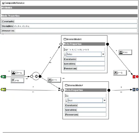
Figure 2.1 A Composite REMES service.
The internal behavior of REMES system is described by modes. Depending on their structure, the modes can be categorized as atomic i.e. modes that does not contain any submodes (AtomicMode1 and AtomicMode2 in Figure 2.1), or composite modes that contain arbitrary number of submodes in their internal structure (CompositeService in Figure 2.1). REMES behavioral language supports transfer of both data and control information. To facilitate the data transfer in the system, REMES provides the data interface, while the control in the system is passed via the control interface. The data interface consists of local and global variables that can be of type boolean, natural, integer, array, clock, etc. The clock type is a special type of continuous variable evolving at rate 1, used to express the timing properties of the system. The control interface of a mode (see Figure 2.1) consists of one or more entry and exit points.
The control flow in a composite mode is represented by a set of dedicated edges interconnecting the control points of the modes. The execution of a composite mode is performed in a sequence of discrete steps. There are two types of actions supported by the REMES language – discrete and delay/timed actions. The delay/timed actions
represent the solution to the differential equations that annotate the models as they describe the continuous behavior of the mode. In Figure 2.1 the AtomicService2 atomic REMES mode has the urgent attribute (marked with U) set to true. With this flag set to true, the mode becomes an urgent mode and it is executed and exited without any delay. The discrete actions are present in a form of annotations on the edges and they are performed instantaneously. Execution of discrete actions result in a change of the executing mode, as the outgoing edge starting from the mode exit point has been taken.
Discrete actions can be formalized as tuples of type A = (g, S) where the S is the action body which can be a statement such as assignment, conditional statement, etc., or a sequence of statements that are executed only when the edge has been taken. The action A is enabled and may be executed only when the action guard g is evaluated to true. The time for execution of a particular mode can be controlled with a predicates over a continuous variables called invariants (expression y <= b in AtomicMode1 in Figure 2.1). Invariants are boolean expressions over system variables used to control the execution/delay time of a particular mode. In addition to atomic modes and edges, a REMES composite mode can also contain conditional connectors (an element decorated with a letter C in Figure 2.1). Conditional connectors allow selection of one of the many possible outgoing edges, based on their respective guards. For a discrete action to be executed, a corresponding guard must be evaluated to true. In case when none of the guards of the discrete actions evaluates to true, no discrete action is executed and the system remains in the current mode. In situations when more than one of the guards evaluates to true, the next discrete action for execution is selected non-deterministically.
REMES language uses special global variables of type clock to model the timed
behavior of the system. The clock variables are of continuous nature evolving at rate 1 (variables x, y in Figure 2.1). If decorated with one, the mode can be exited as soon as the corresponding invariant stops to hold.
To provide the constructs that support SOS modeling, Čaušević et al. have introduced the SOS features into the initial REMES behavioral language [5]. As a result of their work, the initial REMES language has been extended with a service behavioral description that provides means for modeling and analysis of services and service compositions.
The basic functional unit for modeling REMES SOS models is service. A service in REMES is represented with a mode (further in the text we will use the terms REMES
mode and REMES service interchangeably). Just as in REMES behavioral language for modeling ES, the services in REMES for SOS modeling can be either atomic or composite. To enable the service to be published and invoked, a list of attributes has been exposed at the interface of the REMES service. As depicted in Figure 2.1, every service (atomic or composite) is decorated with the following attributes:
▪ capacity – specifies the maximum number of requests (messages) that can be received, handled and served by the service per time unit;
▪ time-to-serve – indicates the worst-case time in which service will receive a request and will respond to it;
▪ service precondition – a predicate that must evaluate to true in order for service to be evoked and executed;
▪ service postcondition – a predicate (Pre: ∑ → Bool, Pre ≡ (PreInit ˅ PreEntry)) that must evaluate to true in order for the service to be invoked. The polymorphic type of state ∑ includes both the local and global variables, and the initial predicates PreInit and PreEntry;
▪ service type – an attribute that determines the type of the service mode. In the current version of the REMES language the only supported service types are: web service, network service and database service;
▪ service status – indicates the current status of a service. Currently supported values are: idle, active and passive (not invoked).
In order to facilitate the service manipulation, the REMES language for modeling SOS has been enriched with interface operations given by a pre- and postcondition specification. REMES behavioral modeling language supports interfaces for creating
and deleting services, creating and deleting service lists as well as adding, removing and replacing services from a service list. The following two examples show interfaces for creating and deleting services:
Create service: create service_name
[pre] : service_name = NULL
Delete service: del service_name
[pre] : service_name ≠ NULL del : service_name → NULL {post} : service_name = NULL
One possible way for new services to be created is through composition of already existing services which are often represented as independent and distributed functional units. The newly composed services must fulfill the imposed requirements which may be continuously evolving as a result of the dynamic composition of the services. To support the dynamic aspects of services in REMES, a new textual hierarchical language for dynamic service composition (HDCL) has been introduced. This new hierarchical language supports modeling of sequential, parallel and nested services. The Dynamic Composition Language (DCL) and Hierarchical Dynamic Composition Language (HDCL) can be described through the formulas (1) and (2):
DCL ::= (s_list, PROTOCOL, REQ) (1)
HDCL ::= (((DCL, PROTOCOL, REQ)+, PROTOCOL, REQ)+, …) (2)
According to the formulas (1) and (2), the HDCL facilitates infinite degree of nesting of DCL. The positive closure operator indicates that HDCL is a result of a nesting one or more DCLs. The type of binding between the services with the hierarchy is defined by the PROTOCOL as:
PROTOCOL ::= unary_operator service_name | servicem binary_operator
servicen
(3)
The requirement REQ is a predicate that includes both the functional and extra-functional properties of a composition. Through the requirement predicate, one can define the capability, characteristics, or quality of service of the system. The unary and binary operators present in the PROTOCOL definition are defined as follows:
unary_operator ::= exec – first (4)
If we consider a situation where two services s1 and s2 are placed into a list denoted
with s_list and we also assume that their execution starts at some given point of time, than the semantics of the unary and binary protocol operators and the correctness of the composition in situation where si Prei represents the strongest postcondition of si,
i 1, 2 with respect to Prei is defined as following:
Exec-first – for a given composition, specifies which service should be executed first. The formal model below shows an example where service s1
should execute first and that service s2 can become active only when execution
of s1 is complete and its postcondition has been established.
statuss1 = active ˄ statuss2 = idle Posts1 → (statuss2 = active) (6)
If we have a list of services, the executing of service s1 fist can be defined as:
Exec – first s1 ∆ s1 ‖¬gs1 (s2 Binary_operator … Binary_operator sn) (7)
Sequential composition – represent composition of two services that are executed uninterrupted in a sequence. The correctness condition of the sequential composition is:
(sp.s2.(sp.s1.Pres1) → Posts2) ˄ (Posts2 → REQ) (8)
The correctness of a Parallel composition (s1 || s2) is defined as:
(sp.s1.Pres1 ˅ sp.s2.Pres2) → REQ (9)
Parallel composition with synchronization: services denoted by S-AND belon to an
AND mode that needs to synchronize their execution at the end of the execution. Considering that, “and” synchronization of those services is defined as follows:
(s1 ‖ SYNC – and s2) (s1, s2 S – AND → (( now · statuss1 = statuss2 =
active) ˄ (starts1 + TimeToServes1 = starts2 + TimeToServes2)))
(10)
The condition for checking the correctness of “and-AND” synchronization is formalized as:
2.3 Timed automata
a) b)
Figure 2.2 Examples of TA.
Timed Automaton [10] represents a finite state machine extended with a finite number of real-valued clocks, introduced to measure the time between occurring events. The basic functional units of timed automaton are locations interconnected between each other with edges. As depicted in Figure 2.2 an automaton can be composed of one or more locations (L0 and L1 in Figure 2.2). Considering the automaton presented in Figure 2.2 b), one can notice that it is composed out of two control locations (L0, L1), two clock variables (x, z), and a synchronization action (synch!). One of the locations (L0) has been marked as starting point and it is regarded as the initial location. The other location in the automaton (location L1 in Figure 2.2 b)) has been decorated with a boolean expression, which represents the
invariant of the location. It defines the maximum allowed time that the automaton is
allowed to spend in that particular location. For illustration the automaton given in Figure 2.2 b) is allowed to stay in location L1 as long as the invariant (x<=7 &&
z<=2) holds.
Transition between locations can occur through the control edges. Considering the Figure 2.2 it is evident that edges have been decorated with boolean conditions called guards (e.g. x > 2 in Figure 2.2 a)), which must evaluate to true in order for an edge to be taken. In addition to guards, edges can be enhanced with actions and assignments. In most of the cases the assignments are used to reset the clock variables or to update the other data variables in the system (x := 0 in Figure 2.2 a)). For example, if we refer to the edge between the locations L1 and L0 in automaton
presented in Figure 2.2 b) we can notice that during the transition both of the clock variables have been reset.
The state of the system is represented though the current location and the values of the clocks while the system is in that location. In TA system, occurring transitions can be either discrete corresponding to a change of the location of the executing automaton or delayed transitions which model the passage of time.
Also, the timed automaton can be executed in parallel for a given synchronization function representing connected network of TA. One such TA network is given in Figure 2.2 where the separate automata synchronize between each other by passing and receiving synchronization actions, given by synch! and synch?, respectively.
2.4 Model-checking
Model-checking also known as model exploration is one of the verification techniques used to establish correctness of a system in early design phase. The other verification techniques on this level are simulation and testing which perform exhaustive experiments over a restrictive set of model or real system scenarios, respectively.
Model-checking is an automated verification technique used to explore all the possible states in the system, based on the brute-force algorithm. The basis of the model-checking techniques is the abstraction of the system under consideration called the model. Baier et al. [6] refer to the importance of the model as following:
“Any verification using model-based techniques is only as good as the model of the system”. By traversing all the system states in a systematic way and applying the
model-checking technique one can verify if the model truly satisfies certain property. The brute-force manner of checking the models is suitable for handling small state set spaces (up to 109 states), while for larger state space sets (with 1020 states or more) the model-checking technique has to be based on clever algorithms and tailored data structures [6]. In the process of traversing the state space, the model-checking technique is capable of discovering errors which is very hard to detect with the process of emulation, testing or simulation.
Figure 2.3 Schematic view of the model-checking approach [6].
Model-checking technique is suitable for checking both the qualitative and quantitative properties of the underlying system. Qualitative approach aims at validating some of the properties of the system such as correctness, reachability, fairness, safety, and etc. Number of situations can be explored by checking the timing properties of the underlying system. Some of the situations include checking whether a deadlock is possible in the system, and if so, will it occur after some time while the system is running? If the response has been received, has it been received within the predefined time frame? Also, due to the fact that the system properties must be precisely defined, the model-checking technique can find potential flaws into the documentation like inconsistencies or ambiguities in the defined properties. The behavior of the system or what the system should do is described with the property specification, while the model description addresses on how the system behaves. In the process of system checking, the model-checker examines all the possible system states and checks whether the desired property has been satisfied. If a state that violates some property has been reached, the model-checker is capable of providing a counter example, showing how the system can be lead into that state. The automated checking process allows constant recheck of the model. This can be very useful if some of the features of the model under consideration have been changed after it has been previously verified. Once the model has been corrected, it can be validated again by reapplying the process of model-checking to uncover potentially introduced errors.
2.5 UPPAAL
UPPAAL is a set of tools based on constraint-solving and on-the-fly techniques for modeling, simulation and verification of real-time systems [8]. It is used for systems that can be modeled as a collection of non-deterministic processes, have a finite structure and real-value clocks and communicate through channels and/or variables. The UPPAAL model-checker is the most suitable for application areas where the timing aspects are critical. By exploring the state space of the system, the UPPAAL model-checker checks the invariant and reachability properties.
UPPAAL toolset consists of three main parts: description language, simulator and a model-checker. The description language serves as a modeling language for describing the system as a network of TA extended with data variables. The language is non-deterministic guarded command language that supports set of data types. Some of the currently supported data types in the UPPAAL language are integer, clock, channel, boolean, etc. The simulator and the model-checker provide interactive automated analysis of the system that has been modeled. Due to the exhaustive dynamic behavior coverage of the system for detecting errors during the model-checking phase, the entire process of verification the model can be very expensive. To overcome this problem, the UPPAAL simulator supports dynamic execution of the system during the design phase. This feature of discovering errors prior the model-checking process minimizes the risk of design errors during the model-checking phase.
UPPAAL supports both textual and graphical formats for the description language. The textual format of the UPPAAL provides basics for a high-level programming language for the TA. In addition to the textual format the graphical interface provides features for system definition in a form of network of TA. In order to provide the WYSIWYV1 feature of the toolset, the compiler performs transformation of the system description in graphical format into textual format.
The UPPAAL model-checker supports verification and validation of temporal properties, such as safety and liveness, specified in a subset of TCTL (timed
computational tree logic) [32] [33]. The UPPAAL toolset simulator visualizes counter examples produced in the process of model-checking and visually points to model errors before the tool performs full formal verification. The UPPAAL TA extends the native TA with notions of bounded integer variables, binary and broadcast channels, and urgent and committed locations.
So, in the next chapter we will elaborate the problem definition of the thesis and we will present the theoretical background in the form of transformation rules for transforming the REMES SOS constructs which are contributions of the thesis.
Through the set of transformation rules we provide the necessary means for transforming the REMES SOS models into TA formal framework.
3 Problem analysis and transformation rules for
transforming R
EMES
SOS modes into Timed Automata
As described in the introduction, the goal of the thesis is to provide support for automated transformation of the REMES SOS models into TA framework suitable for the formal analysis. To accomplish this, we need to provide a theoretical support for transforming all the REMES SOS designing constructs that have been added to the original REMES language. In order to deploy proposed theoretical solution and enable designers to use it, we need to provide prototype implementation in a form of an extension add-on to the REMES IDE for modeling SOS.
In this chapter we will give more detailed overview of the problem that we aim to solve. For that purpose, we will establish the theoretical basis in a form of transformation rules for transforming the REMES modes for SOS modeling into TA suitable for formal analysis. As the REMES SOS language is based on REMES
language for behavioral modeling of ES, the newly defined transformation rules are in compliance with the transformation rules established for the REMES ES models. This set of definitions presented in [9] contains transformation rules for transforming atomic, composite and parallel composition REMES modes into PTA. In this thesis, we propose a modification to the transformation rules to comply with TA, and we also formally define transformation rules for AND and OR synchronized modes typical just for the REMES SOS behavioral language. As a result from our work, we provide all the necessary means to support the formal verification of the newly introduced constructs of the REMES language for modeling SOS.
The chapter is divided into five subsections. In the first subsection we will present the problem definition of the thesis. Second, we present the transformation process for the atomic REMES modes. Third, we define how to transform the REMES SOS composite modes. Later on, in section four we provide the necessary means to facilitate the transformation of parallel compositions of REMES modes into network of TA, and we close the chapter by introducing formal definitions for transforming AND/OR synchronized modes into TA framework.
3.1 Problem analysis
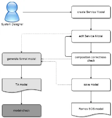
Figure 3.1 REMES IDE user workflow diagram
The problem definition can be presented through a simple scenario performed by the system designer in the process of designing the system. Figure 3.1 depicts a scenario with a typical workflow for designing a SOS model using the REMES tool. The complete workflow has been presented as a set of activities performed by the system designer. If we focus on the workflow, it is evident that the complete set of actions has been divided into two branches of execution. The main branch that spans from top to bottom is composed of actions that are mostly design-oriented. All of these actions are currently supported by the IDE, meaning that they can be automatically performed. On the other side, there is a branch of execution connected with a dashed
line to the main branch. These actions must be performed in order to create formal model of the underlying REMES SOS model. They are marked with gray color to indicate that they are not supported by the IDE, meaning that currently they must be performed by a human verification expert. The problem is however, that in most of the cases the system designer is not a verification expert, so additional actor is required to manually perform these actions in order to formally verify the model by using model-checking technique. Also manual transformation requires substantial amount of time, especially for large and complex systems. Note that the model-checking action is specially marked as it is performed by the UPPAAL tool and is out of scope of our problem.
In order to bridge the gap between the system modeling and the formal analysis of the system, this thesis focuses on defining a set of transformation rules, definitions and techniques that can be implemented as an additional feature to the IDE. To enrich the feature set of the REMES IDE without modifying the core functionalities by any means, the transformation rules has been implemented as an extension add-on. By following this approach, the existing core functionalities of the tool are retained, while new features in a form of an individual module have been added to the host environment. There are number of reasons that motivate the adoption of the UPPAAL toolset as a platform for performing model-checking on REMES models. UPPAAL is an academic tool that can be used freely and without restrictions in the academic research projects, and second it is suitable for modeling the REMES
behavioral models as finite state machines with a support for the timing aspect. To build a formal model suitable for model-checking with the UPPAAL tool, the REMES
SOS model has to be transformed into TA as it is the input language to the model-checking tool.
3.2 Transformation of R
EMESatomic mode into Timed Automata
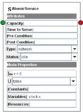
An atomic mode, also regarded as service (see Figure 3.3) in REMES language is defined as a standalone REMES mode that does not contain any submodes in its internal structure. In contrast to this, if an atomic mode exists inside a composite mode, e.g. the AtomicSubMode1 inside the CompositeService depicted in Figure 3.6, then it is called atomic submode.
Figure 3.2 Initial system automaton (global trigger)
Figure 3.3 A REMES atomic mode.
Figure 3.4 Transforming a REMES atomic mode into TA framework.
The timed automaton obtained as a result from transforming a REMES atomic mode given in Figure 3.3 is presented in Figure 3.4. The automaton is composed out of two locations and two edges. The location named as Start is the initial location, whereas
the other location corresponds to the atomic mode that is being transformed. The edge between the Start and the AtomicService location is used for synchronizing the automaton execution with the system start-up activated on broadcast synchronization action marked as start (Start → AtomicService) in Figure 3.4. The purpose of the trigger is to activate the execution of the TA corresponding to the modes in the system, and it is broadcasted from the global trigger automaton presented in Figure 3.2. The second transition represents a looping transition decorated with an activation synchronization channel a1 (AtomicService → AtomicService) broadcasted by the current mode to reactivate itself and synchronize with the other modes in the system.
The mode properties such as the invariant and the urgent flag are translated into properties of the corresponding location. The other properties of the REMES mode (constants, variables and resources) are in fact the declarations of the variables used by the particular mode. They are translated into corresponding declarations of the timed automaton represented by a Template object in UPPAAL.
Figure 3.5 Transforming a REMES atomic submode into TA.
As shown in Figure 3.5 the transformation of a REMES atomic submode results in a single location of a timed automaton corresponding to a REMES composite mode. Similar to the REMES atomic mode, the mode properties of the REMES atomic
submode are transferred to the corresponding location. The location becomes decorated with the same invariant as the REMES atomic mode, and it can also be marked as Urgent or Committed depending on the flags of the submode.
The variables and constants declared in atomic modes are mapped into local variables and constants of the resulting timed automaton. In contrast to this, the resource variables are translated into global resource variables. The currently imposed constraint is that there will be only one resource variable in the system and that it will be of type integer.
The formal definitions for transforming the REMES ES atomic modes and submodes have been presented by Orlić et al. [9]. In our work we have adopted the transformations and give them the necessary means to support SOS distinctive features of the modified REMES language.
3.3 Transformation of R
EMEScomposite mode into Timed
Automata
A composite mode represents a REMES mode which internal structure is composed out of an arbitrary number of atomic REMES modes and conditional connectors. Compared to the transformation of atomic services, the process of transforming composite services into timed automaton is performed in phases, as the process requires translation of the composite mode connection points into locations and elimination of the conditional connectors from its internal structure. The transformation of composite REMES services into timed automaton is performed as following:
▪ translate the composite service connection points; ▪ translate the composite service submodes;
▪ remove the conditional connectors from the composite service inner structure.
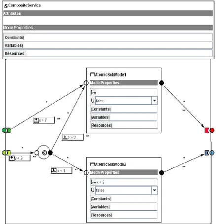
Figure 3.6 A REMES composite service composed out of two submodes and one conditional connector
Figure 3.7 depicts the timed automaton obtained as a result from transforming the REMES composite mode given in Figure 3.6. In the process of transforming the composite mode connection points into locations, following rules apply: (i) a connection point is mapped into a location only if it has input and/or output edges and (ii) the output connection point locations (Exit and Write) must always be marked as urgent. The second rule for transforming the composite mode connection points is introduced to satisfy the “run-to-completion” semantics of the REMES
behavioral language and prevent the timed automaton to stay in those locations. The automaton stays in Start location waiting for the system start-up triggered by the
start broadcast synchronization action (Start → InitPoint). If the Init connection
point of the composite mode has been mapped into a location in the resulting timed automaton, then a transition is constructed to connect this location with the Start location. In the opposite case i.e. when the Init connection point does not map into a location, the initialization transition is created between the Start and the location corresponding to the Entry point of the composite mode. The edge between the InitPoint location and AtomicSubMode2 location in Figure 3.7 corresponds to the edge from the Init connection point of the composite service and the AtomicSubMode2 submode. The same applies to the edge between the EntryPoint and the AtomicSubMode1 location. If we focus on the edge between the WritePoint location and the AtomicSubMode1 location, we can notice that this edge has been decorated with exactly the same properties as the edge from EntryPoint to the AtomicSubMode1. Note in Figure 3.6 that this edge does not exist in the REMES
SOS behavioral model. It has been additionally introduced into the automaton to ensure the internal execution of the composite mode as long as the write edge guard holds. By the time the guard on the write edge stops to hold, the mode is exited in the next execution cycle through the Exit connection point. The return edge from the ExitPoint to the EntryPoint location is introduced in the automaton with the purpose to reset it and enable its reactivation after the execution has finished.
Figure 3.8 A timed automaton generated from transforming a non-lazy sub-mode in the Composite service depicted in Figure 3.6.
The submodes within the REMES composite service are translated according to the transformations rules defined earlier in Chapter 3. The timing properties of the REMES language support specifying the execution time of a mode. To denote the execution time of a REMES mode, a predicate expression over continuous variables called invariant is used. The composite mode presented in Figure 3.6 contains a submode (AtomicSubMode1) that has not been decorated with an invariant expression. Also, the urgent flag of the mode has been set to false. Atomic submodes that are not decorated with an invariant expression and have the urgent flag set to false are classified as non-lazy modes. While the system is in one of these modes, time is allowed to pass until at least one of the guards of the output edges evaluates to true. Because of that, the transformation of the non-lazy modes differs from the transformation rules for the atomic submodes defined in Chapter 3. The automaton presented in Figure 3.8 is corresponding to a non-lazy mode, and it is composed of a location representing the submode and an additional committed location for each of the mode’s output edges.
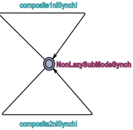
Figure 3.9 An additional automaton used to trigger the edges between the non-lazy mode and the synchronization location as soon as the guard becomes active.
In Figure 3.8 we can see how the non-lazy mode named AtomicSubMode1 placed inside the composite mode in Figure 3.6 has been translated into timed automaton. In the same figure we can notice that the edge between the submode and the Exit connection point of the composite service is split into two parts with an additional committed location between. The first part of the newly created edge is decorated with the same synchronization action and guard as the original edge. The second part of the edge is decorated with the same statement present on the original edge. Also, an additional timed automaton (see Figure 3.9) with one location has been introduced
into the system in order to provide synchronization actions. The depicted transformation of non-lazy REMES SOS mode has been done in compliance with the formal definition specified in [9].
Observe that the synchronization actions in the timed automaton presented in Figure 3.7. The AtomicService3? synchronization action on the EntryPoint output edges comes from the system’s architecture and it ensures the synchronization of the composite service execution upon entrance with the other modes in the system. The other synchronization actions are used to synchronize the composite service (timed automaton) with other services (timed automata) when it finishes execution. These synchronizations can be observed at the output edges of the WritePoint and they are used to trigger the execution of the modes connected to this connection point of the composite mode. When the composite mode does not synchronize its execution with the other modes in the system, i.e. it is not connected to any other mode through its WritePoint, the output edges originating from WritePoint location are not decorated with synchronization actions, like the automaton presented in Figure 3.8.
Notice that the timed automaton presented in Figure 3.7 does not contain conditional connectors. According to the formal transformation definition for the REMES
composite modes specified in [9], the conditional connectors have been replaced with a set of edges defined as ⋃ ⋃ , where i and j denote the number of input and output edges of the conditional connector. Each of the new edges has been constructed as combination of the guards and the statements from the conditional connector’s input and output edges. The edge between the InitPoint and the AtomicSubMode1 locations is produced as a combination of the input edge of the conditional connector and the output edge going towards the submode. The guard at the edge is constructed as a combination of the guards of the combined input and output edges of the conditional connector (y < 3 && z > 2 in Figure 3.7). In this fashion we eliminate the conditional connectors, while retaining the functionality of the resulting TA model.
Note that the definition for replacing the conditional connectors within a REMES
composite mode does not provide the full compatibility. Numerous examples can be presented where the transformation rules for conditional connectors do not result in a correct TA. To avoid erroneous results, we suggest that the resulting TA should be checked by a human verification expert prior the model-checking process in order to validate its correctness.
3.4 Transformation of R
EMESparallel composition into Timed
Automata
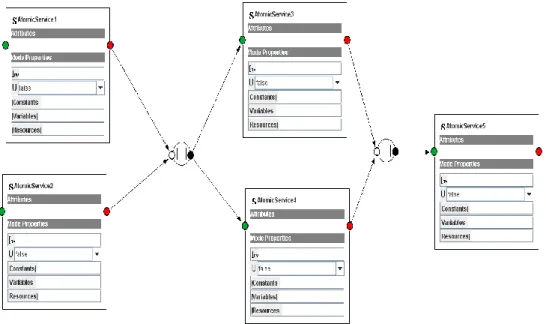
Figure 3.10 Parallel REMES composition
A parallel composition is represented by set of REMES modes, be there composite or
atomic placed between parallel connectors (AtomicService3 and AtomicService4 in Figure 3.10). The parallel composition was introduced in REMES language with a function to synchronize the execution of the REMES modes [5]. The resulting transformation from REMES parallel composition is a network of TA, where each individual timed automaton corresponds to a REMES mode within the composition. To demonstrate how the REMES parallel connection is translated into a network of TA, we present the transformation of one REMES mode from the parallel composition. The timed automaton resulting from the transformation of the AtomicService3 (see Figure 3.10) placed in the parallel connection is presented in Figure 3.11.
Figure 3.11 Timed automaton corresponding to an atomic REMES mode inside parallel composition.
If we observe the Figure 3.11 one can notice that the presented timed automaton corresponding to the AtomicService3 mode matches to great extend with a timed automaton generated for REMES atomic mode placed outside a parallel composition. The only difference between the two automata is on the initialization edges where the automaton has been synchronized with AtomicService1 and AtomicService2 modes, placed outside the parallel composition. This affects only the REMES modes that are directly synchronized with the connectors of the parallel composition. The transformation of the modes that are not directly connected with the output edge of the parallel connector or placed between other REMES modes is not affected by the parallel connectors, as they are translated according to already defined rules for REMES modes.
The difference in transformation of the composite REMES modes directly connected to the parallel connector is on the initialization edge. Similar to the atomic REMES
modes, the transformation created initialization edge for each of the REMES modes to which the composite mode has been synchronized through the parallel connector.
3.5 Transformation of R
EMESAND/OR modes into Timed
Automata
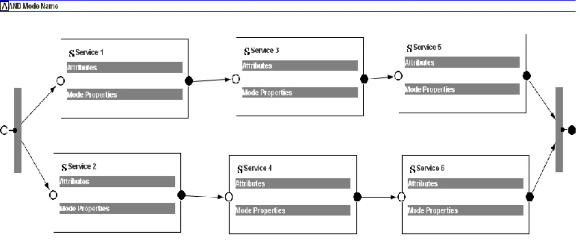
To synchronize the behavior of services, REMES language for modeling SOS introduces a special type of modes called AND and OR synchronized mode [5]. According to the semantic definition, from the view point of an external observer the modes synchronized within the AND/OR mode finish their execution simultaneously. The key difference between the two types of synchronized modes is at the start of the execution of the modes within. In a case of AND synchronized
mode, by default it is assumed that all of the synchronized submode lanes will start their execution at the same point of time. This is due to the fact that the AND synchronized mode does not allow guards at the incoming edges. By submode lane we assume a chain of connected REMES services starting from the input connection point of the synchronized mode and ending up in the output connection point of the same. In contrast to this, the OR synchronized mode allows guards on its incoming edges; therefore the start of the execution of the submode lanes is directly dependent upon the guards. Due to this dependency, the simultaneous execution of the OR synchronized compositions cannot be guaranteed. The AND and OR synchronized modes modeled in REMES SOS IDE are shown in Figure 3.12 and Figure 3.13, respectively.
Similar to the transformation of the parallel compositions, the result from transforming the AND/OR synchronized modes is a network of TA, where each automaton is corresponding to a particular REMES mode existing within the AND/OR mode. As defined by Čaušević et al. [5] AND and OR modes have similar behavior. Direct implication from this great similarity between the synchronized modes is reflected on the transformation rules, which are also similar to a great extent. The differences occur due to the different input and output synchronization of the modes.
Figure 3.13 OR REMES mode
The resulting TA network corresponding to a synchronized mode is produced by transforming all the individual atomic REMES modes placed within the AND/OR synchronized mode. Depending on the synchronization upon the start and the end of the execution, the set of atomic REMES modes within AND/OR mode can be divided into three groups. The first group represents the modes that need to be synchronized at the end of the execution of the AND/OR mode as they are directly synchronized with the output connection point e.g., modes named Service 5 and Service 6 in Figure 3.12 and Figure 3.13, respectively. The second group represents the modes that are synchronized with the input connection point of the synchronized mode; Service 1 and Service 2 in Figure 3.12 and Figure 3.13 belong to this group of modes. The third group of modes (also referred as the middle layer) are the ones that are not directly synchronized with the AND/OR mode connection points. Typically in synchronized REMES modes, these modes are placed between the modes synchronized with input and the modes synchronized with the output connection points of the AND/OR mode. Service 3 and Service 4 in Figure 3.12 and Figure 3.13 belong to this group of modes.
a)
b)
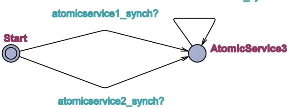
Figure 3.14 Transforming REMES atomic modes synchronized with the Init/Entry location of the AND/OR mode.
The above introduced classification of the modes inside synchronized modes is crucial for the implementation, as different transformation rules apply for the different groups of modes depending on their synchronization. Figure 3.14 depicts the resulting TA produced from transforming the REMES atomic modes synchronized with the Entry connection point of the AND/OR mode. From the presented TA we can see that these atomic REMES modes have been transformed in compliance with
the rules for transforming atomic REMES modes introduced earlier in Chapter 3. In
this particular case, the synchronization channel present on the initialization edge (atomicservice1_synch in Figure 3.14 a) and b)) has been used to synchronize the modes’ execution with another mode placed outside the synchronized REMES mode. The connection between these two modes is the input connection point of the synchronized mode, through which the first mode within the REMES synchronized mode is aware of the modes outside the composition. At the same edge, there is a difference in a statement set between the modes placed inside AND and OR synchronized modes. In Figure 3.14 a) corresponding to the mode placed in an AND synchronization mode one can notice that the statement set is empty i.e., the initialization edge has not been decorated with any statements. In contrast to this, it is evident that the same edge of the timed automaton presented in Figure 3.14 b) is corresponding to the atomic REMES mode within OR synchronized mode has been decorated with a statement (ORMode3_SYNC_VAR_VALUE = ORMode3_SYNC_VAR_VALUE + 1) that increments the counter variable by one.
started with execution. This feature is an essential part of the mechanism used for avoiding deadlock situations when translating OR composition modes into TA network.
The section continues as following. First we present a formal definition for transforming REMES atomic modes directly connected to the Entry connection point of the AND/OR mode. Secondly, we provide formal definition for transforming atomic REMES modes connected to the Exit connection point. We conclude the
chapter with explanation about transforming the middle layer REMES modes inside
AND/OR mode by using existing transformation rules presented earlier in Chapter 3. If we assume that NM is the set of all modes that are part of the AND/OR mode and are directly synchronized with the Entry point of the AND/OR mode, we can then formally define the transformation into a network of TA in Definition 1.
Definition 1. Let NM be the set of atomic modes of the AND/OR mode that are
connected to the Entry point of the AND/OR mode denoted with MAO. The
transformation r2t NM → NT transforms these modes into a network of timed
automata. The transformation r2t of a set NM is performed by transforming the
individual modes M ϵ NM into corresponding automata am ϵ AM, respectively, where
|NT| = |AM|. Additionally, we define a “counter” variable MAO _SYNC_VAR ϵ Vt,
where Vt is a set of data variables of the AND/OR mode. The variable keeps track of
the number of the invoked submode lanes within an AND/OR mode: when a submode lane within the AND/OR mode is invoked, the counter is incremented.
The transformation of the modes synchronized at the exit of the synchronization REMES mode (see Service 5 and Service 6 in Figure 3.12 and Figure 3.13) has to provide synchronization with the corresponding network of TA for atomic modes synchronized at the end of the execution. Figure 3.15 and Figure 3.16 present timed automaton obtained as a result of transforming REMES atomic modes synchronized upon the end of the execution of AND and OR modes, respectively.
Figure 3.15 Transforming a REMES atomic mode synchronized at the end of execution of the AND synchronized mode.
The mechanism added to the timed automaton in order to provide a synchronization of modes at the end of the execution of an AND/OR mode consists of an integer variable (ORMode3_SYNC_VAR in Figure 3.16) and an additional committed location (location decorated with C in Figure 3.16). The integer variable has been introduced into the system to count the number of the exit atomic modes that have finished execution. This is very important, as only the last mode that executes within the synchronized mode is broadcasting a signal on synchronization channel in order to invoke the execution of the next modes in the system.
According to the formal definition [5], AND/OR synchronized modes are allowed to operate in one of two possible regimes: and or max. The operating regime captures the behavior of the AND/OR modes upon finishing the execution. If a particular AND/OR mode is operating in and regime, it is expected that all exit atomic modes finish execution simultaneously, while if the synchronized mode operates in max regime the synchronized mode finishes its execution when the last mode in the synchronized composition completes its execution. Our proposed synchronization mechanism is tailored to satisfy both of the synchronization regimes.
To ensure the synchronization at the end of execution, the synchronization edge connecting the location corresponding to the mode (OrModeName_Service6 in Figure 3.16) and the initial location (location marked as Start in Figure 3.16) of automaton has been split in two parts with a committed location (location decorated with C Figure 3.16). On the transition between the location corresponding to the atomic mode and the committed synchronization location the counter variable (OrMode3_SYNC_VAR Figure 3.16) has been updated, indicating that the current mode has finished its execution. There are two possible execution paths between the committed location and the initial location of the automaton i.e. there are two reset edges for the automaton. On both of the edges it is tested whether the mode finishes execution before, or it finished last or simultaneously with the other modes. If we go back to the Figure 3.12 and Figure 3.13 again we can notice a difference in the statement for comparing the value of the variable between the AND and OR synchronization modes. In the AND mode the counter variable is compared with a number equivalent to the number of executing compositions, while in the OR mode the same variable is compared to a zero value constant, after decrementing it first. This is the variable that was introduced in the transformation of the modes connected to the input connection point of the synchronization mode. The purpose of this
variable is to count the number of modes that have started the execution before the synchronized mode finishes its execution. This feature is crucial for the OR synchronized mode since it allows guards at the output edges from the input connection point. Without this variable, there is a possibility that some of the guards on the input edges will not evaluate to true thus resulting in not invoking some of the input modes, so the submode lanes following it would never be executed. This situation can consequently lead to deadlock at the exit of the AND/OR mode.
The AND synchronized modes are not prone to a deadlock problem, due to the fact that all of the input modes are executed simultaneously and all of the executing submode lanes are expected to finish in some point of time, avoiding a possible deadlock situation at the end of the execution.
If we assume that Nm is the set of all modes that are part of the AND/OR mode, and that are connected directly to the Exit point of the AND/OR synchronized mode, we can then formally define the transformation into a network of TA in Definition 2.
Definition 2. Let NM be the set of atomic modes of the AND/OR mode that are
connected to the Exit point of the AND/OR mode denoted with MAO. Assuming that M
ϵ NM, then the transformation r2t NM → NT transforms these modes into a network
of timed automata. The transformation r2t of a set NM is performed by transforming
the individual modes M ϵ Nm into corresponding automata am ϵ AM, respectively,
where |NT| = |AM|. Additionally, we define a “counter” variable MAO _SYNC_VAR ϵ
Vt, where Vt is a set of data variables of the AND/OR mode. The variable keeps track
of the number of the invoked submode lanes within an AND/OR mode, (that is, the counter is decremented at each invocation), and when it reaches 0, the AND/OR mode finishes its execution by broadcasting a synchronization action MAO _SYNC.
The third group of REMES modes within AND/OR synchronized mode are the ones that are not synchronized with the connection points of the AND/OR synchronized mode. These modes are placed between the modes synchronized with Entry connection point and the modes synchronized with Exit connection point of the AND/OR synchronized mode (see Service 3 and Service 4 in Figure 3.12 and Figure 3.13). For these modes, the transformation rules for transforming atomic REMES
mode apply without any changes. The timed automaton obtained from transforming the modes is presented in Figure 3.17.
a)
b)
Figure 3.17 Transforming REMES atomic modes inside AND/OR mode not connected to the input or the output pin of the AND/OR mode
In this chapter we have introduced all the theoretical rules required to perform transformation from REMES SOS modes into TA framework suitable for the formal analysis with UPPAAL tool. In the next chapter we will give a complete overview of the defined transformation rules and their implementation as an extension add-on to the REMES IDE to perform an automated generation the TA formal model. Step-by-step we will go through each phase of creating the tool, from defining the static structure until reaching the complete functionality. We will wrap up the presentation of the extension tool by presenting how the formal verification module has been added to the IDE and how designer can use its functionality.
![Figure 2.3 Schematic view of the model-checking approach [6].](https://thumb-eu.123doks.com/thumbv2/5dokorg/4718679.124462/19.918.240.679.131.430/figure-schematic-view-model-checking-approach.webp)