Malmö University
Faculty of Technology and Society
Department of Computer Science
Emergency Communication
Bachelor Thesis 15 HP
Abdulrahman E. Aburawi
Sarija Salic
Degree:
Bachelor Programme in Computer and Telecom Engineering: Technology and Management, 180 HP
Speciality: Computer Science
Supervisor: Magnus Krampell
Examiner: Ulrik Eklund
i
Abstract
Even in the 21st century, modern communication technology is still affected by natural disasters and political turmoil which threaten people’s lives and make the internet or mobile phone networks unavailable for use. This work uses systems theory which resulted in a proof of concept system that uses shortwave radio technology to provide a one-way communication system. A message a user writes on their smartphone, which is connected to a small pre-set transmitter, is sent out to a receiver in another part of the world where the message can then be posted on the internet. This system is a cheaper alternative to other shortwave radio transmitters, and has potential for improvement.
ii
Acknowledgements
We would like to thank our supervisor Magnus Krampell for his time, helpful advice, and his enthusiasm throughout this work.
iii
Contents
Abstract ... i
Acknowledgements ... ii
1.
Introduction ... 1
1.1
Background ... 1
1.2
General Problem ... 1
1.3
Aim ... 2
1.4
Limitations ... 3
2. Related Works ... 4
Handover Based Emergency Communication Scheme ... 4
Gotenna ... 4
Amateur Radio for Major Disasters ... 4
Application of Telemedicine ... 5
IRDR ... 5
Relation to Minimum Requirements ... 5
3. Theory ... 6
3.1 Introduction to Shortwave Radio Communication ... 6
3.1.1 History of Shortwave Radio ... 6
3.1.2 Conditions for Stable Shortwave Communication ... 6
3.1.3 Summary ... 7
3.2 Radio Data Modes ... 7
3.2.1 Packet: ... 7 3.2.2 RTTY: ... 8 3.2.3 AMTOR: ... 8 3.2.4 PACTOR I: ... 8 3.2.5 PACTOR II: ... 9 3.2.6 PACTOR III: ... 9 3.2.7 QRSS: ... 9 3.2.8 PSK31: ... 10 3.2.9 WSPR: ... 10 3.2.10 Feld-Hell (Hellschreiber): ... 10 3.2.11 JT9, JT65, JT4:... 11 3.3 Phone Connectivity ... 12 3.3.1 Wi-Fi ... 12 3.3.2 Bluetooth ... 12 3.4 Antenna ... 12
4. Method ... 14
System Studies and Goal Programme ... 14
System Synthesis ... 14
System Analysis ... 15
System Evaluation and Decision ... 15
System Implementation Plan ... 15
5. Results ... 16
iv
5.1.1 Choice of Phone Connectivity: Wi-Fi or BT? ... 16
5.1.2 Connecting User’s Phone to transmitter ... 17
5.1.3 Proof of Concept Phone Connectivity ... 17
5.2 Solution Part 2: Transmitter ... 18
5.2.1 Arduino with QRSS-shield ... 18
5.2.2 Mode to Transmit: QRSS ... 18
5.2.3 Proof of Concept Transmitter Implementation ... 19
5.3 Solution Part 3: Receiving ... 25
5.3.1 Software: CwGet and N1MM ... 25
5.3.2 Receiving Computer ... 25
5.3.3 Proof of Concept Receiver Implementation... 26
5.4 Overall Proof of Concept Implementation ... 26
5.5 Usability and Comparison ... 28
5.5.1 Usability Test ... 28
5.5.2 Comparison with Related Work ... 28
5.6 Discussion ... 30 5.6.1 General Discussion ... 30 5.6.2 Legality ... 32 5.7 Conclusion ... 33 5.8 Future Work ... 34
6. References ... 35
Appendix A: Glossary ... 39
Appendix B: Code ... 40
Appendix C: Schematic for Wideband Amplifier ... 41
1
1. Introduction
1.1 Background
In light of recent world events, like the Arab Spring and significant natural disasters such as the 2010 Haiti earthquake, modern telecommunication is still susceptible to both government interference and the unpredictable harshness of nature. Mobile telephone networks in Haiti were damaged and heavily overloaded (Digicel, 2010), and during the 2011 revolution in Libya the government stopped all internet traffic in and out of the country (Dainotti et al., 2011). During these events the lives of many people were endangered and they were in desperate need of foreign aid, which could no longer be reached by usual means.
1.2 General Problem
How can people communicate over long distances in a way that is both cheap to use and not too technically advanced for the user when there is no internet and no mobile phone networks available? The most fundamental requirements for such a system would be:
Easy to use; no advanced user expertise required
Easy to install, if not already in place
Cheap to operate
Long range communication; at least 1000 km
Available for many users
An existing solution to this issue is the satellite telephone. However, it has a high initial cost as well as a high minute rate. It is also illegal or restricted in some countries such as India (Kumar, 2011) and Burma (Dobie, 2007). There are only a handful of operators to choose between, and some of them do not have complete global coverage. It was also recently shown that satellite phones have security flaws that make them vulnerable to eavesdropping (Driessen et al., 2012) so they are not ideal for use by political dissidents.
A viable alternative is to use shortwave (SW) radio. While transmitting SW radio requires some theory knowledge and training, it uses little power and has an impressive range: a shortwave radio broadcast can be heard thousands of kilometres across the earth with just a simple radio receiver. In contrast, not only is a satellite phone expensive to obtain and use, it would also require a specific telephone number for a call to be made to, which is asking a lot for someone in an emergency situation. They may not know anyone who lives in another country, and it is unlikely for them to have a foreign telephone number. On the other hand, a shortwave radio transmission is nonspecific, much like a typical SOS signal which is meant for anyone who can receive it.
If a SW radio transmission can be originated from a person’s smartphone, it would remove the barrier of technical knowledge required for SW radio transmitting, since a person is familiar with their own phone. However, a smartphone cannot transmit SW radio signals on its own, and a mobile application (app) would require an internet connection, therefore the phone would have to be connected to a device that can transmit these signals. This device can be pre-installed with software and hardware that when connected to a user’s phone can take a text message and send it as a SW radio signal. All the user has to do is set up the device and its antenna, connect their phone to it, write a text message and hit “submit”. This is so that the user does not have to concern themselves with what frequency to transmit at,
2
or how much power to use, or any other technical requirements. Once transmitted, the signal can be picked up by a receiver which then converts the radio signal back to text, so that it can then be posted on the internet where it will have a bigger reach. The system’s ease of use means that it can be used by anyone who is familiar with a smartphone, since they do not need to know how SW radio transmitting works. A more detailed list of requirements is presented below (see Table 1).
Req. no.
Type (m/i/n)
Requirement
R1 m The transmitter uses shortwave radio signals for
transmission
R2 m Works with at least 15 metres between phone and
transmitter
R3 m Works with both Android and iOS smartphones
R4 i No pre-installed app required
R5 i Transmitter connects to user’s phone wirelessly
R6 m Simple transmitter set up process
R7 m Direct text entry for message sending
R8 i Transmitter operates continuously at least one week without charging
R9 n Encryption of user data and message
R10 m Message can be posted on the internet/social networks
R11 n Transmitter uses solar power for charging
R12 i Fully automated frequency setting
R13 m Non-directional antenna
R14 i Lightweight transmitter, easy to move around
R15 i Capacity of 10000 messages/day from 10000 people, each
message sent 10 times during 12 hours
R16 i Send signal multiple times
R17 m Minimum 1000 km range to receiver
Table 1: list of specific system requirements. Key: m = minimum, i = ideal, n = nice to have
Minimum requirements are the ones considered the most important and essential, such as the ability of the system to work with either Android or iOS smartphones. Ideal requirements are not vital to the system but are implemented if possible. Finally, requirements labelled as “nice to have” are seen as a bonus for the system.
1.3 Aim
The aim of this work is to develop a proof of concept for a one-way emergency communication system that uses shortwave radio signals to broadcast a user’s message to a different part of the world. What are the possibilities available for building a shortwave radio based communication transmitter? This work systematically analyses the potential technological choices that can be used for the system and provides recommendations for suitable technologies to be implemented for the different parts of the system. These alternatives together make up a proof of concept, which is tested for its overall functionality. This is done primarily with ready-made components based on the Arduino platform, since it is an established and open source tool with high flexibility and potential.
3 Figure 1: System overview.
1.4 Limitations
Working with Arduino means that this work is limited to only use compatible hardware. Another limitation is what equipment is available at the university. Also, since testing the system transmitting and receiving simultaneously would require long distance travel, which is not feasible within the scope of this work, radio receivers already available on the internet are used instead.
4
2. Related Works
The following is a summary of the most similar related research and projects in the area of emergency communication. These works were found via a thorough search through the database of the IEEE and online search engines. At first, broad keywords were used, such as "shortwave", "emergency", "disaster", "communication", etc. to narrow down the results to the most comparable works, before again using the keywords found in these articles to find more relevant works.
Handover Based Emergency Communication Scheme
Ramesh and Nisha (2011) suggest a system which relies on smartphones, laptops and emergency vehicles to expand a cellular network by establishing access points when an emergency situation causes disruption in cellular towers. This relies on there being at least one functioning cellular tower in the area, so that devices can act as smaller cells in a network. Service can change between wi-fi and GSM (Global System for Mobile Communications), creating a mesh network that extends the reach of information as long as emergency vehicles can move across land. The network’s structure means that no new technology is required, since only familiar devices are used.
Gotenna
Gotenna is an emergency communication device currently under development by a small company in the United States. It is a small device which connects to the user’s phone via Bluetooth to send text messages to other gotenna users depending on ground elevation and environment; the range is lower in built-up areas and higher in clearer, flat areas. A special app must be downloaded on the user’s phone prior to use. It works as a simple messaging system where the user can also attach their location to their message. This device is developed for when there is no phone network or internet, and is made to be easy to use for anyone with a smartphone. It operates at a specific frequency, and the user does not have to have any knowledge of radio communication. All they have to do is pair the device with their phone using Bluetooth, which many people are already familiar with doing for their car, headset or other phone accessories. Gotennas operate on their own network, meaning that text messages can only be sent between gotenna equipped phones (Gotenna, 2015).
Amateur Radio for Major Disasters
Cid and Mitz (2011) developed an emergency e-mail service that a radio operator may use to connect three hospitals in Maryland, USA to the internet when communications are cut in their area. The hospitals use a local network where they can send information to each other via internal e-mails through a local server. When they need to connect to the outside world, they message the radio operator who then broadcasts their e-mail as a high frequency SW radio signal which is sent via the Winlink 2000 radio messaging system (ARSFi, 2015). An alternate solution involves the radio operator using a portable radio transmitter, which can only handle the needs of one of the three hospitals at a time. This is also used when a field team is sent do deal with an emergency far from the hospitals. However, the e-mail system has limited bandwidth and during development it was observed that it can easily reach full capacity if too many large e-mails or replies are sent at a time. The radio operator is responsible for ensuring that external e-mails are handled and broadcast correctly, since the system is not fully automated. While the portable solution means the radio broadcaster is not tied to one specific location, they must still be close enough to one of the hospitals to connect via their wi-fi, meaning that the application of this system is only specific to the area around the three hospitals in Maryland.
5
Application of Telemedicine
In 1996 the US Department of Defence started a medical network serving troops in Bosnia and other countries to help military medical personnel communicate with each other using real time-voice data and video for consultation and diagnosis. In Bosnia a satellite provided direct broadcast capability which made it possible to transmit radiographs and other medical images to field hospitals for expertise support. These links connected army field physicians with other physicians at five different regional military medical centres in the United States, which made it possible for the medical units to use full-motion remote video tele-consultation, and access medical records and other critical information. To do so, the system used an integrated form of relay ISDN (Integrated Services Digital Network) architecture. The main hub was in Germany, implemented using the internet and a commercial ISDN gateway linked further out to the rest of the world. Large nodes were placed at the MASH (Mobile Army Surgical Hospital) in Tuzla, Bosnia. The MASH was then connected by two T1 satellite circuits which made it possible to interact with medical centres in the United States when the specific clinical expertise was not immediately available and the situation was urgent in Bosnia (Garshnek and Burkle, 1999).
IRDR
The International Radio for Disaster Relief is a project for coordinating the use of shortwave radio frequencies for amateur radio operators around the world during natural disasters. It has an automated system that checks its global database of frequencies every ten minutes to see if they are in use. If any changes are made, the online database is updated and any possible collisions, i.e. the same frequency being used by more than one transmitter at the same time, are identified and avoided. All participants around the world can check which frequencies are available for use. Different humanitarian relief organizations can start their relief broadcasting directly after a real disaster strikes, and coordinate their timeslots among themselves (HFCC, 2015).
Relation to Minimum Requirements
The following table shows which minimum requirements from Table 1, Chapter 1.2 are fulfilled by the above works.
Related Work Minimum Requirements Fulfilled
Handover Based Emergency Comm.
System
R2, R3, R13
Gotenna R1, R2, R3, R6, R7, R13
Amateur Radio for Major Disasters R1, R10, R13, R17
Application of Telemedicine R7, R10, R13, R17
IRDR R6, R10, R13, R17
6
3. Theory
3.1 Introduction to Shortwave Radio Communication
Shortwave radio is a means of radio transmission which operates at the frequency range of 3 to 30 MHz. It was developed by radio pioneer Guglielmo Marconi as an alternative to longwave radio and its issues regarding long distance communication (Hawkins, 1995). Longwave transmissions required large transmitters, a lot of power, and were only effective at certain ranges. Shortwave radio signals travel by reflecting between the ionosphere and the Earth's surface, requiring less power and covering long distances across continents. In modern times, with the rise of the mobile telephone and the internet, shortwave radio has become much less prevalent but it is not only used by hobbyists, it is also in use by some embassies (Washington Times, 2009), military forces and coast guards (USCG, 2013).
3.1.1 History of Shortwave Radio
In the early 20th century, wireless radio communication was limited to using longwave signals, which only functioned between a few European countries and the United States. Worldwide wireless communication had not yet been realised (Hawkins, 1995). Wireless radio played a big part in World War I, and many soldiers developed an interest in this technology and became amateur experimenters using shorter wavelengths, but this made for unreliable communication. Guglielmo Marconi, who helped develop the telegraph from a wired to a wireless means of communication, wanted to further study other ways of wireless radio that could have a worldwide reach. Since all longwave frequencies were already in use, he turned instead to shorter wavelengths. Marconi’s assistant engineer Charles S. Franklin began experimenting with shortwave signals in the 1920s. These experiments included a transmission with a range of 100 miles (160 km) using only a 700 watt transmitter, and lead to transmissions that could reach 1000 miles (1609 km) and further. One such transmission was sent from a transmitting station in Poldhu, England to Marconi’s yacht as he sailed around Cape Verde in the Atlantic Ocean. Later he also successfully broadcasted a speech from Poldhu to Sydney, Australia. Shorter waves meant that simpler antennae could be used, and less power was required to transmit signals than with longwave frequencies. Near the end of the 1920s commercial shortwave transmissions became a viable means of communication between US and Europe.
3.1.2 Conditions for Stable Shortwave Communication
The earlier instances of shortwave radio communications over longer distances with the use of low power were first attributed to transient and unusual combinations of different conditions. The people who were involved with these experiments involving shortwave radio communication were first called “freaks”. However, further tests showed that these earlier results were in fact often obtainable, which attracted a lot of interest from other experts and commercial companies (Edes, 1930). Together they concluded that to successfully establish a stable shortwave radio communication, four important factors must be considered. They are listed in the table below.
7 Range
The transmitter and receiver have to be within a minimum distance from each other, which is calculated as the great circle distance between the two points on the Earth’s surface.
Geographical positions of stations
Aside from the distance between them, the longitude and latitude of the transmitter and the receiver must also be considered.
Time of year, time of day
Solar radiation changes during the seasons due to the solar cycle, and the preferred frequencies vary with the time of year as well. In other words it is important to use a frequency that is ideal for the current season. It also depends if the signals are transmitted during daylight hours or night.
Frequency MUF (Maximum Usable Frequency) is the highest radio frequency that can be used between two points via reflection by the ionosphere. Table 3: List of factors for stable shortwave radio communication.
3.1.3 Summary
Shortwave radio communication may be old but it is still used even in the 21st century. And although there are a number of conditions that must be met for optimal use, it is feasible with minimum means, making it ideal for use in emergency situations when other communication technology is unavailable.
3.2 Radio Data Modes
Through the years a large number of new digital operating modes have been developed, due to the increased availability of computers, soundcards and software. Amateur digital communication started in the early 1940s when hams experimented with techniques of connecting mechanical teletype/printers to amateur equipment using FSK (Frequency Shift Keying) and AFSK (Audio Frequency Shift Keying). Digital radio modes are often accomplished by a TNC (Terminal Node Controller) modem or through an interface with a computer’s soundcard (Radio Amateurs Of Canada Inc, n.d.). Since the supervisor for this work is a licensed amateur radio operator, he was consulted on the subject of digital radio modes, which lead to an independent study. Combined with the requirements for this work, the most suitable and accessible modes are listed below.
For help with specific terms in this section see the glossary (Appendix A).
3.2.1 Packet:
Packet is simply a form of computer networking that uses radio links instead of wires. It has a data rate of 1200 bytes/s (SYMEK, 2015). Packet mode communicates by sending packages of small data to its clients. If a data package is received by the client without any errors, the sending computer receives an acknowledgement and the next data package is transmitted. If there is any problem during transmission, the client refuses the package by not sending an acknowledgement and waits for a repeat. This type of data exchange protocol is known as X.25 and was adapted for amateur radio use and called AX.25, where the A stands for Amateur. It works on the same principles the packet bundles were sent but now the network is wirelessly connected by radio through interfacing devices such as TNCs. Packet mode is considered an augmenting mode, since it is used to expand the enjoyment of amateur radio. By connecting to the local PBBS (Packet Bulletin Board System), which is used to send
non-8
real-time messages to people in a similar way to email, it is possible to read bulletins from other amateurs regarding a wide range of topics. However working with HF (High Frequency) packet requires a bit of skill and practice: it must be tuned properly and the margin for error is narrow (Ford, 1992).
3.2.2 RTTY:
RTTY (Radioteletype) has its beginnings during World War II when the military began connecting mechanical teletype machines to HF radios. At first they attempted to use simple on/off keying as a means of sending text, but the results were not as they first expected. After some investigation the engineers switched to FSK (Frequency Shift Keying) and RTTY was born. It still remains a popular communication mode on amateur HF bands because of its long range. On the receiving end, RTTY decodes the information by detecting the pulse state of the incoming signal. Common use in RTTY jargon is to say “mark for the pulse on and space for the off pulse”; the difference between the mark and space frequencies is the shift in FSK modulation. One of the biggest advantages of RTTY is that no matter how old any SSB (Single Side Band) transceiver is, it can be used for RTTY. With a data terminal or computer and an RTTY modem it is possible to be up and running very quickly. The disadvantages however are its slow data rate of only 5.7 B/s (Adrio Communications, n.d.), also its demodulators cannot sort out multiple signals on the same frequencies and it is not uncommon that only the strongest stations have a chance to be recognized among a group of signals (Henry, 1992).
3.2.3 AMTOR:
Amateur Teleprinting over Radio, or AMTOR, is based on an existing radio teletype system which is designed for maritime communication and has the ability to maintain communication even when the signal is very weak, with a data rate of 12.5 B/s (NADARS, n.d.). It is very similar to RTTY, as it also uses FSK (Radioteletype, see above). The significant difference is that AMTOR uses an error correcting system which is similar to Packet (See Packet 3.2.1). AMTOR has two different modes. The primary one is called ARQ (Automatic Repeat Request), where the ISS (Information Sending Station) sends three characters and stops. The IRS (Information Receiving Station) checks each character for the 4:3 ratio code and replies with a single control character which means “ACK” (Acknowledged) so the ISS can continue sending the next three characters. The IRS can also return a “NAK” (Not acknowledged) control character so that the ISS sends the three characters again. This process is looped through until the character group is sent without any errors. The second mode is FEC (Forward Error Correction) where the ISS sends the complete text without stopping. As the name implies, FEC also includes error correction; it sends each character twice with the repeats delayed by four characters. The disadvantage working with AMTOR is that proper tuning is critical; even a slight frequency change can disrupt the link. Also, an AMTOR controller must receive multiple ARQ characters before it can synchronize to the received signal (Henry, 1992).
3.2.4 PACTOR I:
The PACTOR mode can be viewed as a combination of two older digital modes: packet radio and AMTOR. PACTOR radio equipment consists of an HF transceiver, a computer and a TNC, where software running on the computer drives the TNC. The mode uses FSK and ASCII characters that have been compressed with a Huffman algorithm. The compression reduces the average character length for improved efficiency. The synchronous transmission system that PACTOR uses has packet duration of 0.96 seconds, a CS (Control Signal) duration of 0.12 seconds and an idle time of 0.17 seconds, making a total cycle time of 1.25
9
seconds and speed of 25 B/s. The sending station is called master and the receiving end is called slave. The mode sets of an ARQ (Automatic Repeat Request) for packets that fails in the CRC (Cyclic Redundancy Check), the receiving end sends a control signal as an acknowledgment. Repetition of the same CS is a request for a packet to be repeated. Although it is a reliable mode, PACTOR transmissions have the potential to disrupt other modes of communication on the same and even nearby frequencies. It also uses data compression technology where the decompression algorithm is not publicly available, meaning that the content of a PACTOR transmission can only be read by a PACTOR TNC (Karty, n.d.).
3.2.5 PACTOR II:
A backward compatible improvement to PACTOR I. It is an adaptive mode that applies different modulation and encoding methods depending on the channel quality. To achieve a link setup, PACTOR II uses PACTOR I and an automatic handover to PACTOR II is only made if both stations are capable. PACTOR II uses DPSK (Differential Phase Shift Keying) unlike PACTOR I which uses FSK (Frequency Shift Keying). Without compression the highest data transfer PACTOR II can provide is 700 bit/s, or 87.5 Bytes/s, but with real-time data compression the rate can reach as high as 1200 bit/s, or 150 B/s. Similar to PACTOR I, PACTOR II is half-duplex protocol that uses ARQ to acknowledge each data packet with a short CS. The improved error control coding makes it possible to operate on circuits with a lower signal-to-noise ratio than PACTOR I can tolerate. PACTOR II also has a feature where it automatically switches to longer packets when the transmitter indicates that more information has to be transferred (Karty, n.d).
3.2.6 PACTOR III:
PACTOR III is a software upgrade for the earlier PACTOR II modems that enables a new data transmission mode for improved speed and stability. For a fully established PACTOR III connection both the transmitting and receiving stations must support PACTOR III. Because it builds on PACTOR II most specifications are the same, but the most significant difference is PACTOR III’s multi-tone waveform which uses 18 carriers compared with only two in PACTOR II. The maximum uncompressed speed for PACTOR III 2722 bit/s ( 340 B/s ) and using online compression, speeds up to 5200 bit/s (650 B/s) are possible. As with the earlier PACTOR-modes it requires a HF transceiver, a computer and TNC (Karty, n.d).
3.2.7 QRSS:
With QRSS, data is sent as a very slow CW (Continuous Wave) signal, resembling Morse code, usually with FSK (Frequency Shift Keying). The slow data rate means that it can use a very narrow bandwidth, so that noise becomes less of a concern, which is suitable for when propagation conditions are poor. It is also effective because the faster the signalling rate, the more bandwidth is needed which is equal to more energy (e.g. transmitting power) to keep the signal above the noise. To be able to operate with QRSS it requires a QRSS transmitter and the most critical requirement for this transmitter is to ensure good short and long-term frequency stability. For example the centre of QRSS activity is in the 30 metre band between 10.140000 MHz and 10.140100 MHz which means any small frequency error will result in the signal possibly falling outside of the QRSS sub-band (100 Hz wide sub-band), which reduces the chances of receiving confirmed reception reports of the signal. Receiving QRSS requires hardware: a receiver for QRSS and a computer with a sound card, and software for receiving and displaying QRSS signals, such as “Agro”, “Spectran” and “Spectrum Lab”. However
10
working with QRSS also requires patience. Since its transmission depends on the prevailing propagation conditions, it may take time before the signal is confirmed (Turner, 2012).
3.2.8 PSK31:
PSK31 works by changing audio tones to deliver the transmission content, where characters are represented as a binary sequence of 0’s and 1’s. While operating in the QPSK (Quadrate Phase Shift Keying) mode errors are corrected using a Viterbi decoder. This decoder can store in its memory its guesses for the past 20 received symbols and can use that data to calculate how well the phase shifts match. This operation however causes a delay of 640 ms. PSK31 achieves its weak-signal performance as a result of two factors. The first is that a PSK31 signal is narrow being around 31 Hz wide. Secondly, the receiving end can anticipate the times for each data bit, due to the use of varicode, a variation of Huffman code. Disadvantages of PSK31 however are a slow data rate of 4 B/s, its sensitive tuning process, and that it needs stable VFO’s (Variable Frequency Oscillator) (Karty, n.d.).
3.2.9 WSPR:
Weak Signal Propagation Reporter is a program made with an emphasis on low power radio transmissions. It has its own messaging protocol, meaning that custom messages are difficult to implement. The computer using WSPR must have its clock synchronised with WSPRnet, WSPR's public online database. This mode is designed for extremely weak signals and uses structured messages with a high degree of compression, forward error correction, an embedded sync vector to establish accurate time, frequency offsets between transmitter and receiver, and 4-tone FSK. This also leads to a very slow data rate of 0.2 B/s (ARRL, n.d).
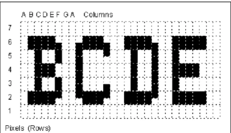
3.2.10 Feld-Hell (Hellschreiber):
Instead of converting text to the binary system, Feld-Hell or Hellschreiber represents the actual shape (fonts) of the characters themselves by translating them into various combinations of tones. Hellschreiber has come out in different variants throughout the years such as PSK (Phase Shift Keying) Hell which encodes the pixel brightness in the carrier phase instead of the amplitude and FM (Frequency Modulation). In the receiving end the software decides if the pixels on a particular area of the screen should be dark or light, writing down the text on the monitor in the process (see fig. 2 below). This mode was frequently used during World War II, where messages were printed on paper. To make a high performance digital radio mode, DSP (Digital Signal Processing) has been added and the most common mode in use today is Feld-Hell. It transmits text in a similar manner to the printing of a dot-matrix printer. Where a black dot is required the CW transmitter is keyed, and when nothing is sent the colour is white. The characters are made by scanning up each column of the character from left to right and if the speed is varying the text will climb up or slide down because there is no connection established. It may be an old radio mode, but it does not require high power, is simple, inexpensive and gives good performance even as a slow speed of 15.3 B/s (Greenman, 1999).
11
Figure 2: Hellschreiber character matrix (Greenman, M. 1998 p.4).
3.2.11 JT9, JT65, JT4:
JT9 is a relatively new mode designed especially for use on the MF (Medium Frequency) and LF (Low Frequency) bands, and shares many qualities with the other popular modes JT65 and JT4. They are all created for making contact under extreme weak-signal conditions and all use the same message and source encoding FSK. JT4 is mainly used on the microwave bands and JT65 used on the VHF/UHF bands and even on the worldwide QRP communication at HF. JT9 is optimized for different frequency bands (1.8 MHz, 472 kHz and 137 kHz) and has been found to be useful also at HF while using less than ten percent of time T/R (transmit/receive) sequences. The sub modes with longer transmissions trade reduced throughput for smaller bandwidth and increased sensitivity. However the JT-modes are very slow, with a maximum data rate of 0.5 B/s (Taylor Jr., 2014), and can be confused with a “birdie” signal, which can be described as a false signal that can appear in the receiver (Anon, n.d).
12
3.3 Phone Connectivity
For communication between the user’s smartphone and the transmitter unit, wireless communication is ideal since the user does not have to be directly near the transmitter. This is preferable to having users connect their phones straight into the transmitter, since it might have to be placed in a high place for better shortwave signal propagation. For wireless connectivity there are two choices to examine.
3.3.1 Wi-Fi
Wi-Fi is an IEEE standard of wireless communication, officially designated as IEEE 802.11. It is a widely used technology thanks to its relatively long reach and high bandwidth. It can be secured with varying levels of password encryptions, or not secured at all to allow completely open availability to any compatible device within range.
3.3.2 Bluetooth
BT (Bluetooth) is another wireless communication standard, which operates at a frequency range near wi-fi. Class 2, which is the type of BT used in mobile phones, has a range of around 10 metres. For two Bluetooth enabled devices to connect to each other, they must first confirm the connection with a shared PIN code (Dhawan, 2011).
3.4 Antenna
According to Abercrombie (2005) shortwave radio communication offers a broad range of compatible antennae. Some are easy to build and use, while others require more knowledge and parts, such as tuners. Since these antennae are aimed at amateur radio users, many of them can be considered incompatible with the needs of this work. Following requirements R6 (ease of use) and R13 (non-directional antenna) in Table1, Chapter 1.2, many of the more technically advanced antennae can be ignored and the options narrowed down to two possibilities. First is the common whip antenna (fig. 3) that is widely used due to its simplicity. It does not need to be set up in a specific way since it is non-directional, so the user does not need to know which way to point it when transmitting. A telescopic whip antenna does not take up any space during transport, which makes it easier to handle. Secondly there is the wire antenna, also known as the half-wave dipole antenna (fig. 4). It is a simple antenna system which is fed with a coaxial cable and no tuner. The feed-point impedance is 75 ohms at regular heights but can also be fed directly from the output of modern radios.
13
Figure 3: Whip antenna, with ground plane (Sirio Antenna, 2015).
14
4. Method
The chosen working method for this research is the systems theory, which according to Pahl et al. (2007) is an important and effective way of designing a technical system. An iterative approach was taken when using this method, since some steps may require repeated use, as seen in figure 5. A couple of steps were merged together since they are tied together in the context of this work. These are System Studies and Goal Programme, as well as System Evaluation and System Decision.
Figure 5: Overview of the systems theory (Pahl et. al., 2007, p.16).
System Studies and Goal Programme
The first steps of this approach are problem analysis and formulation, which were done by producing a pre-study. This includes gathering information from databases, advice from the supervisor's expertise in the subject of shortwave radio communication, as well as internet searches, since as it turned out this is where the most relevant information on the SW radio is found. The pre-study resulted in outlining the aim of this work, including the creation of a list of requirements (see Table 1, Chapter 1.2) as well as studying a number of related works (see Chapter 2). The requirement list serves as a basis for evaluating the system later on (see Chapter 5.7).
System Synthesis
Once information is gathered and system goals are set, the next step is to synthesise a number of solution variants. Chapter 3 names the possible solutions for different parts of the system. For example, Chapter 3.3 shows the possible technologies that are considered for communication between the user's phone and the transmitter. A central factor of synthesis is
15
the limitation of using Arduino for the system, as mentioned in Chapter 1.4. This means that a solution variant's compatibility with Arduino had to be considered in the following step.
System Analysis
The next step in this method is to analyse solution variants for their properties and behaviour. This is done by experimenting with a solution variant to see how well it works at realising the goals of the work. One example of this is the work done coding the phone connectivity (see Chapter 5.1.3). A part of this analysis is the chosen variant's compatibility with Arduino.
System Evaluation and Decision
For evaluating system, the solution variants are checked with the requirement list (see Table 1, Chapter 1.2), and depending on how well the minimum requirements are fulfilled a decision is made whether this variant is suitable or if any previous steps should be reiterated. For Decision, see Chapter 5.1, 5.2 and 5.3. For Evaluation, see Chapter 5.7
System Implementation Plan
Finally, once the parts of the system have been decided, their implementation is shown. This is essentially the whole report, but specifically Chapter 5.1.3, 5.2.3 and 5.3.3. Figure 16 shows an overview of all the implemented parts of the system working together.
16
5. Results
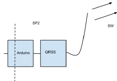
The proof of concept is made up of three parts, as shown below in fig. 6. They are presented in the subchapters below.
Figure 6: The three Solution Parts (SPs) of the system.
5.1 Solution Part 1: Phone Connectivity
5.1.1 Choice of Phone Connectivity: Wi-Fi or BT?
Wi-Fi and Bluetooth share a number of similarities, but wi-fi has the advantage of a much higher range, as well as less steps to establish a connection between the transmitter and the user’s phone. As part of the system evaluation and decision, a comparison was made between the two choices, and since only wi-fi was able to comply with R2 in Table 1, being able to work with a distance of 15 metres from the transmitter it was decided that wi-fi should be used.
17
5.1.2 Connecting User’s Phone to transmitter
Wi-Fi is used to connect the user’s smartphone with the transmitter. The user opens a web browser and types in the IP number in the address bar to interface with the transmitter. This is a simple page where the user writes a message into a textbox and presses a “submit” button.
Figure 8: How the webpage looks on a smartphone, in this example an iPhone 6.
5.1.3 Proof of Concept Phone Connectivity
The implementation of Arduino was decided early on in the work, since it is a central part of the synthesis of the other solutions used in this work (see System Synthesis in Chapter 4 Method). The basis for the transmitter hardware is an Arduino Leonardo microcontroller. Arduino is an open-source platform that is made for programing and constructing electronics. Like other microcontrollers, Arduino is a circuit board with a processor chip that can be programmed to do different things: it can read information from input devices e.g. antennae, sensors, trimmers and also send data to output devices like LEDs, speakers, LCD screens and DC motors. With wi-fi or Ethernet shields the Arduino can also be connected to the Internet. A shield is a circuit board expansion that can be connected to the Arduino circuit board. The software is a simplified variant of C++ to programme the board, which makes it easy to learn and to program. Unlike most previous programmable circuit boards Arduino does not need to have a separate piece of hardware to load new code onto the board; this is made easy by using a USB cable (Badamasi, 2014). It also has a small size, 5 by 7 cm, which makes it very portable and thus ideal for use in this proof of concept.
An Ethernet shield was chosen, since a wi-fi shield, while ideal for this work, would only allow the Arduino to function as a wireless client and not a server. The Ethernet shield was connected to an AP (Access Point), which allows clients to connect to the server that is the Arduino and its Ethernet shield. This way the transmitter uses wi-fi so that users can connect their phones to it.
To fulfil the ease of use requirement, the connection process is made as easy as possible. Following the simple instructions enclosed with the transmitter, the user switches on the transmitter, and activates wi-fi on their phone. They see the SSID (Service Set Identifier) for the transmitter’s wi-fi network, e.g. “Transmitter 145”, and connect to it. After successfully connecting, they open the phone’s browser and go to the URL (Uniform Resource Locator) specified, e.g. 192.168.2.50 in Appendix D. This gives them the webpage to write down their message (see fig. 8). Once the message is entered and the user has pressed the “Submit” button, the next step is transmitting the message, which is explained below.
18
Figure 9: Overview of phone, access point and transmitter with mounted Ethernet shield.
5.2 Solution Part 2: Transmitter
5.2.1 Arduino with QRSS-shield
The transmitter is composed of an Arduino Leonardo with a QRSS shield connected to a dipole wire antenna. Here the user’s message string is converted into a radio signal and sent over shortwave.
Figure 10: Overview of the transmitter.
5.2.2 Mode to Transmit: QRSS
Upon further investigation during system analysis of the listed digital radio modes, use of Hellschreiber requires a decoder and RTTY requires a modem that was not available.
19
However, an Arduino compatible QRSS shield was available early on in the project, which made the decision to work with QRSS for the proof of concept easier, instead of risking any potential delays. Although QRSS is slower than most other modes, according to the requirements list in Table 1 there are no disadvantages choosing QRSS over Hellschreiber or RTTY.
5.2.3 Proof of Concept Transmitter Implementation
Figure 11: The transmitter, consisting of an Arduino Leonardo with Ethernet and QRSS shields. In this proof of concept the transmitter only has to be programmed once and after that it can be used from an independent power source. The chosen QRSS Arduino shield, made by QRP Labs (2015), is a pre-defined crystal controlled Arduino compatible circuit capable of transmitting radio signals with QRSS. The shield came with pre-written code, which can only transmit a fixed string of a text already defined in the code e.g. the user’s radio call sign. This code was modified so that instead of a static message it would take the message a user enters from their phone, by filtering the HTTP header (readString) to eliminate any unnecessary characters, and saving it as the variable named “finalString” so that only the entered message is converted into a radio signal. The dipole antenna was chosen since it is effective at transmitting shortwave signals without needing a specific directivity. This way the end user does not have to consider the directivity when using the transmitter. With QRSS, the transmitter operates at a frequency range around 10.14 MHz, so the wavelength is calculated as . To construct a half wavelength dipole antenna, the required length was calculated as: The wire was cut into two ends at 7.4 m each and fed with a coaxial cable to the QRSS shield. The power outputted by the transmitter and into the antenna has a peak-to-peak voltage of 6.2 volts. The power is (
√ )
, or 96 mW. While this was reasonable for the QRSS shield, the signal was not strong enough to be seen on any online receivers, so an amplifier was added (see fig. 12 and Appendix C), which increased the power into the antenna. Now with a peak-to-peak voltage of 19.4 volts, the power is calculated to be (
√
)
20 Figure 12: Picture of the amplifier.
The transmitter’s signal reached receivers located in Belgium, England and Italy. These receivers have locator codes with which the exact distance the signal has travelled can be calculated. Amateur radio operators use a co-ordinate system known as the Maidenhead Locator System, which uses geographical coordinates based on longitude and latitude. The proof of concept transmitter’s Maidenhead locator is JO65LO in Malmo, Sweden. All map images are © 2015 Google, GeoBasis and TerraMetrics.
-Figure 13: The great-circle distance between the transmitter and the receiver in Belgium.
First there is a receiver located in Maarkedal, Belgium (fig. 13). The distance from the transmitter to this receiver is 820 km. As shown in figure 14 the QRSS Morse code signals do in fact correspond to the call sign that has been transmitted.
21
Figure 14: The signal received in Belgium, edited with letters to clarify the Morse code.
22 Figure 16: Calculating the distance to the receiver in Italy.
Another receiver found 1141 km away from the transmitter with the power of 1W is located in Desenzano Del Garda, Italy (fig. 16). It can be seen receiving the signal below.
Figure 17: Signal received in Italy.
In figure 17 the signal is the upper one, here standing with the last letter of the call sign “K” before sending the call sign again from the beginning.
23 Figure 18: The middle characters of the signal.
Figure 19: The last characters of the call sign, followed by the first ones again.
The signal could also be seen received by a radio beacon in Reading, England which was 1028 km away from the transmitter and was transmitting with a power of 100 mW.
24 Figure 20: Distance to Reading.
In the images below (fig. 21 and 22) the signal is the lower one out of the two.
25 Figure 22: Transmitter signal received in Reading.
5.3 Solution Part 3: Receiving
5.3.1 Software: CwGet and N1MM
The receiver consists of an Afedri SDR Net receiver, a computer with Windows XP and the following software: CuteSDR (Wheatley, 2015) for demodulating the signal, CwGet (DXsoft, 2015) to decode the signal into readable characters and N1MM Logger (Gauthier, 2014) to save the message as plain text. From there the text can directly be saved and posted on any website.
Figure 23: Overview of the receiver.
5.3.2 Receiving Computer
Due to physical limitations regarding the possibility to travel more than 1000 km to actually receive the shortwave transmitted message, the proof of concept was made in two stages. Locally using the equipment explained below, the signal was decoded so it can be showed in
26
plain text. The second stage was to transmit the signal out in the world with the online receivers as marks to see how far the message can reach. The stages were simultaneously done.
5.3.3 Proof of Concept Receiver Implementation
Figure 24: The received signal as seen in the program CuteSDR.
The radio signal sent out by the transmitter is picked up by a computer with an SDR (Software Defined Radio) receiver, which reads signals via its antenna and uses the computer’s sound card and software (CuteSDR) to process these signals as audio signals so they can be decoded by other software on the computer. In this case these signals are decoded by CwGet, which displays the letters based on which Morse code signals they correspond to. The program N1MM Logger reads these letters from CwGet and displays them in plain text which can then be saved on the computer.
Figure 25: The test message, as seen previously in fig. 8, received and decoded multiple times during testing. Here it is displayed in the software N1MM Logger.
5.4 Overall Proof of Concept Implementation
As figure 26 below shows, all the solutions are brought together to make up the whole system. It starts with the user connecting to the AP and writing a message on their phone (see fig. 8) which is sent through the Ethernet shield to the Arduino. The message is broken down so that each letter or number is represented by a byte which is sent as a shortwave Morse code signal (see Chapter 5.2). Once this signal reaches a receiver (see fig. 24) it
27
decodes the message, which in this example is the test phrase “This is a test message” as seen in figure 25. Due to legal reasons (see Chapter 5.7.2) and the lack of a real emergency situation it was necessary to run the system locally with the test phrase instead of a radio call sign. The full solution, from phone to transmitter to receiver, is tested locally and proven to work. 'This is a test message' is written on a phone and it ends up in the receiving end. The very same hardware and software of the transmitter are used to send the local test message as well as the call sign seen in the figures in Chapter 5.2.3 which was received in Belgium, England and Italy.
28
5.5 Usability and Comparison
5.5.1 Usability Test
To cover multiple requirements (see Table 1, R2 to R7) an experiment was made where ten test users were chosen at random from around the university campus. They were given a paper with instructions (see appendix D), placed at least 15 metres away from the transmitter and their time was recorded to see how long it would take to connect to the transmitter, write down a message of up to 140 characters and submit it. Afterwards they were asked if the system was easy to use. If the connection took longer than five minutes the test was aborted. The result can be seen in Table 4 below.
Table 4: Results of the experiment.
To determine the success of this test, two requirements were established. Firstly, the average time should not exceed three minutes and secondly, that at least seven out of ten people would find the system easy to use. As seen in Table 4 the average time was calculated to be 01:31, one minute and thirty one seconds, and that nine out of ten users found it easy to use. The exceptions were user number 4 who did not fully understand the instructions, and user number 5 who did understand the instructions but the connection between the phone and the transmitter took longer than the five minute maximum.
5.5.2 Comparison with Related Work
5.5.2.1 Handover Based Emergency Communication Scheme
While the handover-based system requires no new equipment, it still relies on an already established mobile phone network to extend. If the mobile network is shut down completely the system loses its starting point. In contrast, the system developed in this work functions without having to rely on an existing mobile phone network. It also has the advantage of only using shortwave radio communication, compared to the handover system’s heterogeneous mix of mobile phone network and wi-fi, which have too many discrepancies e.g. in terms of range: if only wi-fi capable devices are available the network will only have a small reach. Even if the mobile phone network can be used it is likely to be congested after the disaster has occurred, as was the case in Haiti (Digicel, 2010). Expanding an already malfunctioning network is not an ideal solution to communication problems.
29
5.5.2.2 Gotenna
When compared with the gotenna, the proof of concept in this work has the advantage of a much larger communication range. The gotenna can only be used with other gotennas, whereas this work is designed to function with any type of QRSS compatible radio receiver around the world. As of writing, the gotenna is still under development and can be pre-ordered US$149.99, half of the recommended retail price (RRP) of US$299.99 which is how much it will cost once released.
The gotenna device itself is roughly as large as a typical smartphone, has a lithium-ion battery and extendable antenna. It uses VHF radio signals to communicate with other gotennas, and is equipped with flash memory that can save hundreds of messages according to its developers. Since these devices operate in a closed network with a maximum range of 6 miles (9.7 km) in clear areas and 1 mile (1.6 km) in built-up areas, this means that as long as none of the gotenna users can connect to the internet, then their messages cannot reach anyone outside of their area. The developers also state that gotennas cannot operate as a mesh network due to restrictions by the Federal Communications Commission (FCC).
5.5.2.3 Amateur Radio for Major Disasters
The emergency e-mail developed for the Maryland hospitals by Cid and Mitz, which indeed can be used without mobile phone networks or the internet, still relies on a trained shortwave radio operator. This means a layman cannot operate it, as opposed to the proof of concept in this work which can be operated by any person without any training requirements. There is also the matter of the hospital e-mail system being specific to the location of the Maryland hospitals, which have to have a separate intranet implemented before the system can be used. In contrast, the proof of concept transmitter requires no pre-existing infrastructure.
5.5.2.4 IRDR
The IRDR project is merely an online database for radio operators and organisations, who are expected to both provide their own radio equipment and have an internet connection to access the database. These conditions are not compatible with the aims of this work in regards to providing radio communication to untrained people without the need for an internet connection. However, the proof of concept uses QRSS which operates on a bandwidth between 10.140 and 10.141 MHz, so using multiple transmitters simultaneously would require some coordination so that the signals do not potentially interfere with each other.
30
5.6 Discussion
5.6.1 General Discussion
The methods used to evaluate the system were chosen from the ones suggested by Hevner et al. (2004). Experimental evaluation was chosen and performed throughout the development of the system. A descriptive evaluation method is also used, comparing this proof of concept to the related works previously mentioned in Chapter 2 (as seen in Chapter 5.5.2).
As originally intended in the list of specific requirements, shown in Table 4 below, all the minimum requirements are successfully fulfilled and even most of the ideal requirements as well. The transmitter uses shortwave radio signals for transmission (R1) as shown in Chapter 5.2. User friendliness has been important throughout development; allowing a person who is in an emergency situation to use their own smartphone gives them a great advantage since they are familiar with their phone and do not have to learn how to use an entirely new device. The HTML page and input process (R7) is also made simple, and as shown in the usability test above (see Table 4, Chapter 5.5.1) there is a success rate of 90%, proving that this system truly is easy to use. This test also shows that the system is compatible with both Android and iOS smartphones (R3). The user enters a message for sending which is transmitted multiple times (R16) and has been proven to reach least 1000 km (R17, see Chapter 5.2.3) without the need for a pre-installed app (R4). The transmitter uses a non-directional half-wave dipole wire antenna (R13) and its small size makes it easy to carry it around (R14). With the use of CwGet and N1MM Logger it is possible to obtain the received transmission in plain text so it can then be shared online (R10).
Req. no.
Type (m/i/n)
Requirement Fulfilled
R1 M The transmitter uses shortwave radio
signals for transmission
Yes, transmitter uses a digital mode of SW radio named QRSS, see 5.2
R2 M Works with at least 15 metres
between phone and transmitter
Yes, tested during Usability Test, see 6.1
R3 M Works with both Android and iOS
smartphones
Yes, system was tested with both operating systems, see 6.1
R4 I No pre-installed app required Yes, text is inputted via the
phone's browser, negating the need of an app, see 6.1
R5 I Transmitter connects to user’s phone
wirelessly
Yes, phone connects to
transmitter with wi-fi, see 6.1 R6 M Simple transmitter set up process Yes, test users were successfully
able to use the system with provided instructions see 6.1 and Appendix. D
R7 M Direct text entry for message sending Yes, a HTML page allows the user to input text, see fig. 8
R8 i Transmitter operates continuously at least one week without charging
No, currently the transmitter works with DC power, see Discussion R9 n Encryption of user data and message No, encryption not currently
31
R10 m Message can be posted on the
internet/social networks
Yes, received signal is decoded as plain text and can be posted online, see 5.3.3
R11 n Transmitter uses solar power for
charging
Not currently implemented, see Discussion
R12 i Fully automated frequency setting Yes, transmitter uses a fixed frequency of 10.140 MHz, see 5.2.3
R13 m Non-directional antenna Yes, transmitter connects to a
dipole wire antenna, see 5.2.3 R14 i Lightweight transmitter, easy to move
around
Yes, transmitter is based on Arduino platform of small circuit boards, see 5.2.3
R15 i Capacity of 10000 messages/day
from 10000 people, each message sent 10 times during 12 hours
Not currently attainable, see Discussion
R16 i Send signal multiple times Yes, signal is sent as long as the transmitter has power, see 5.3.3 R17 m Minimum 1000 km range to receiver Yes, signal successfully reaches
multiple locations more than 1000 km away fro the transmitter, see 5.2.3, fig. 13-22
Table 5: list of specific requirements and how well they are fulfilled.
The proof of concept transmitter is produced in a way that the user does not need to set the frequency to be transmitted at, since it is pre-set (R12). The transmitter is connected to its power source and antenna, and then it is switched on and can start taking messages from user phones as soon as they connect to it via wi-fi (R2, R5). The only part of installing the system which may prove challenging is setting up the antenna, since it is best to place it in as high a place as possible, such as the roof of a building or between large trees. This requires an able-bodied person who may have to climb up structures, so it is still entirely feasible (R6). With this all of the minimum requirements are achieved, as well as most of ideal requirements. The only exceptions are encryption (R9), solar power (R11), working without recharging (R8) and high capacity messaging (R15). Since these requirements fall into the “ideal” and “nice to have” categories, they are not critical for the success of this work but can certainly be an asset.
The transmitter only uses a total power of 3 Watts during operation, low enough to be powered by batteries, or even solar power. Only a power adapter has been used during development but it is entirely possible to connect the device to a solar panel which can generate enough power to operate the transmitter. The transmitter has a power of 3 Watts, and for it to be working 24 hours per day would mean that it uses 3*24 = 72 Watt hours, or 0.072 kWh of energy. To determine a suitable solar panel, two things must be considered: the first is how many sun hours are available, which is the duration of sunshine in a single day, and the second is the efficiency of the solar power system, since not all solar energy can be used or stored. To obtain an approximation, a calculation is made where the number of solar hours is five, and the system efficiency is 70%. One day of charging with a solar panel can be calculated to produce 0.072/5= 0.014 kW, which when adjusted for efficiency is 0.014*.7= 98 Watts. This means that a 100 Watt solar panel is suitable for powering the transmitter, and it can be connected to a 12 VDC battery which charges during the day and allows the transmitter to work at night when there is no sun. Powering a 3 W device with a 12 V battery means it has a current of
= 0.25 ampere. A 12 V battery with a capacity of 50 Ah (Ampere hours), such as a typical car battery, can power the transmitter for 50/0.25 = 200
32
hours before being completely discharged. However, for the battery to remain effective it should only discharge 50%, meaning that it can work continuously for 100 hours before having to be recharged.
As shown in figures 20 and 24 above, the transmitter has successfully transmitted its signal more than 1000 km and to different locations as well. An issue faced during development was the limited number of online receivers, most of which are in Western Europe, and many of these were less than 1000km away, such as the ones in Sweden, Norway and the Netherlands.
The Arduino has a very small working memory, called static random access memory (SRAM), which is only 2 kB. It cannot perform all the required tasks of receiving a message from a user's phone, converting it to a radio signal and sending it to the QRSS card simultaneously or for more than one user at a time. This means that while many users can connect to the transmitter via wi-fi, only one can send a message at a time. This is because text is saved as string objects in the Arduino's SRAM, where each character takes up one byte. Since the SRAM saves the unfiltered text as a string object, and then filters it and saves it as a new string object, this means that the SRAM becomes full very quickly. An unfiltered message has a maximum size of 160 bytes, before it is filtered and stored as a new string variable with a maximum of 140 characters, meaning that each message requires 300 bytes of SRAM to process. While there is enough memory for multiple messages, the Arduino can only run one process at a time, so it is not possible for it to process two different messages from two different users at the same time. Though once a message is written, filtered and converted to a radio signal, the final step of the process is looped and the message can be broadcast multiple times for many hours on end, as seen previously in Chapter 5.7.
As shown in Chapter 3, there are many technological choices for building a communication system based on shortwave radio. And despite the limits due to budgetary concerns as well as its general requirements, the proof of concept produced by this work shows that it is possible to develop a shortwave radio communication system that fulfils four out of five general requirements (see Chapter 1.2)
.
The only requirement that has not been fulfilled is the ability for many simultaneous users (see also Table 5, R15) due to the limitation of the QRSS transfer speed. This can be resolved if a faster mode, e.g. PACTOR II, is used in combination with a more powerful microprocessor. Then it would be possible for 10000 messages to be sent in the span of 12 hours, which is feasible with 25 transmitters for an estimated time of 2 minutes per message, or 4 minutes per message with 50 transmitters. In the case of PACTOR II, which has a speed of 87.5 B/s (Bytes per second), this is enough time for the message to be sent multiple times.5.6.2 Legality
During development it was ensured that all local laws regarding radio transmission were followed correctly. In Sweden, the Swedish Post and Telecom Authority, or PTS, is the government agency that regulates electronic communication such as the internet, telephony and radio. According to the PTS Code of Statutes (PTS, 2014):
An automated transmitter should always be identifiable by sending a call sign in Morse code, or as a voice message, or by any other means.
The call sign should specify the person responsible for the automated broadcast, who should have an amateur radio license and an authorised call sign.
Whoever starts or uses an automated radio transmitter should have an amateur radio license and an authorised call sign.