SKI Report 2005:58
Research
The Swedish Concept for Disposal of
Spent Nuclear Fuel: Differences Between
Vertical and Horizontal Waste Canister
Emplacement
D. G. Bennett
T. W. Hicks
October 2005
SKI perspective
Background
The Swedish Nuclear Fuel and Waste Management Company (SKB) is expected to base its forthcoming licence applications on a repository design in which the waste canisters are emplaced in vertical boreholes (KBS-3V). However, SKB has also indicated that it might be possible and, in some respects, beneficial to dispose of the waste canisters in horizontal tunnels (KBS-3H).
Purpose of the project
The aim of the work is to identify the key differences between the KBS-3V and KBS-3H designs in terms of their potential implications for long-term safety. Processes and features addressed within this study include e.g. temperature, gas pressure build up and release, bentonite swelling and erosion, and tunnel stability for the two different designs.
Results
The report confirms that SKB has identified key factors that will determine the evolution of a KBS-3H repository. Planned research and development work seem to be directed to the areas where the differences between the KBS-3V and KBS-3H designs are significant in terms of repository performance.
Performance assessments of the KBS-3H system will need to take into account a wide range of effects, including certain combinations of effects, which may be significantly different and potentially of relatively greater importance in the KBS-3H system than in the KBS-3V system: canister evolution, near-field flow and transport, gas generation, accumulation and transport.
The report concludes that not enough information is available to select between the two designs at this stage.
Effects on SKI work
The work has given SKI insight on which effects have relatively greater importance in the KBS-3H concept compared to the KBS-3V concept. This will be used in SKI’s forthcoming reviews of SKB’s RD&D programme and in the review of Posiva’s and SKB’s planned safety assessment for the KBS-3H concept in 2007.
Project information
Responsible for the project at SKI has been Öivind Toverud. SKI reference: SKI 2005/493/200509071
SKI Report 2005:58
Research
The Swedish Concept for Disposal of
Spent Nuclear Fuel: Differences Between
Vertical and Horizontal Waste Canister
Emplacement
D. G. Bennett
T. W. Hicks
Galson Sciences Ltd
5 Grosvenor House
Melton Road
Oakham
Ruthland LE 15 6AX
United Kingdom
October 2005
This report concerns a study which has been conducted for the Swedish Nuclear Power Inspectorate (SKI). The conclusions
Executive
Summary
The Swedish Nuclear Power Inspectorate (SKI) is preparing for the review of licence applications related to the disposal of spent nuclear fuel. The Swedish Nuclear Fuel and Waste Management Company (SKB) refers to its proposals for the disposal of spent nuclear fuel as the KBS-3 concept.
In the KBS-3 concept, SKB plans that, after 30 to 40 years of interim storage, spent fuel will be disposed of at a depth of about 500 m in crystalline bedrock, surrounded by a system of engineered barriers. The principle barrier to radionuclide release is a cylindrical copper canister. Within the copper canister, the spent fuel is supported by a cast iron insert. Outside the copper canister is a layer of bentonite clay, known as the buffer, which is designed to provide mechanical protection for the canisters and to limit the access of groundwater and corrosive substances to their surfaces. The bentonite buffer is also designed to sorb radionuclides released from the canisters, and to filter any colloids that may form within the waste.
SKB is expected to base its forthcoming licence applications on a repository design in which the waste canisters are emplaced in vertical boreholes (KBS-3V). However, SKB has also indicated that it might be possible and, in some respects, beneficial to dispose of the waste canisters in horizontal tunnels (KBS-3H).
There are many similarities between the KBS-3V and KBS-3H designs. There are, however, uncertainties associated with both of the designs and, when compared, both possess relative advantages and disadvantages.
SKB has identified many of the key factors that will determine the evolution of a KBS-3H repository and has plans for research and development work in many of the areas where the differences between the KBS-3V and KBS-3H designs mean that they could be significant in terms of repository performance.
With respect to the KBS-3H design, key technical issues are associated with: 1. The accuracy of deposition drift construction.
2. Water inflow to the deposition drifts from fractures in the host rock and the ability to seal such fractures.
3. The ability of the buffer and distance blocks to seal the deposition drifts. 4. Piping and erosion of the bentonite buffer.
5. Supercontainer liner corrosion and interactions with bentonite. 6. Evolution of processes and materials within failed canisters. 7. Gas generation and flow.
Although these issues represent potentially important uncertainties for the KBS-3H design, it should be noted that the most important of them (Issues 2, 3, 4, 6) also apply
Contents
1 Introduction...1
2 The KBS-3V and KBS-3H Designs...2
2.1 KBS-3V ...2
2.2 KBS-3H ...3
3 Differences Potentially Affecting Performance...5
3.1 Operational Issues ...5
3.2 Post-Closure Issues...6
3.2.1 Thermal Issues...6
3.2.2 Hydrological Issues ...9
3.2.3 Mechanical Issues...11
3.2.4 Chemical and Biological Issues...13
4 Performance and Safety Assessment...16
4.1 Canister Evolution ...16
4.2 Near-Field Flow and Transport ...18
4.3 Gas Generation, Accumulation and Transport ...19
5 Conclusions and Recommendations...21
1 Introduction
The Swedish Nuclear Power Inspectorate (SKI) is making preparations for the review of licence applications related to the disposal of spent nuclear fuel. The Swedish Nuclear Fuel and Waste Management Company (SKB) refers to its proposals for the disposal of spent nuclear fuel as the KBS-3 concept.
In the KBS-3 concept, SKB plans that, after 30 to 40 years of interim storage, spent fuel will be disposed of at a depth of about 500 m in crystalline bedrock, surrounded by a system of engineered barriers. The principle barrier to radionuclide release is a cylindrical copper canister. Within the copper canister, the spent fuel is supported by a cast iron insert. Outside the copper canister is a layer of bentonite clay, known as the buffer, which is designed to provide mechanical protection for the canisters and to limit the access of groundwater and corrosive substances to their surfaces. The bentonite buffer is also designed to sorb radionuclides released from the canisters, and to filter any colloids that may form within the waste.
SKB is expected to base its forthcoming licence applications on a repository design in which the waste canisters are emplaced in vertical deposition holes (KBS-3V). However, SKB has also indicated that it might be possible and, in some respects, beneficial to dispose of the waste canisters in horizontal deposition drifts (KBS-3H). Safety assessment studies of the KBS-3 concept need to take account of the arrangement of the waste canisters in the repository because a potentially large number of processes that may influence the performance of the disposal system and its components are sensitive to the spatial distribution of the canisters. Examples of such processes include heat and fluid flow. There are additional differences between the KBS-3V and KBS-3H designs that need to be considered. For example, the KBS-3H design includes a perforated cylindrical steel liner around the bentonite clay. This liner may influence the way in which the clay hydrates and swells in response to water inflow.
This report has been developed by Galson Sciences Limited on behalf of SKI. The report aims to identify the key differences between the KBS-3V and KBS-3H designs and highlight their potential implications for long-term safety. Section 2 outlines the KBS-3V and KBS-3H designs, based on information from SKB. Sections 3 and 4 identify and discuss issues where the differences between the designs have some potential to affect repository operation, performance, and safety, and might warrant further analysis and regulatory scrutiny.
2
The KBS-3V and KBS-3H Designs
This section provides a summary of the KBS-3V and KBS-3H designs, highlighting the main differences between them. The summary is based principally on information presented in SKB (2004, R-04-42).
2.1 KBS-3V
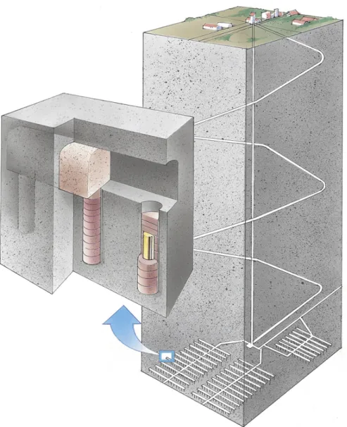
The KBS-3 concept for storage of spent nuclear fuel is illustrated in Figure 2.1. Figure 2.1 depicts the KBS-3V design variant in which vertical waste deposition holes extend downwards from larger horizontal deposition tunnels, which would subsequently be backfilled. In the KBS-3V design, each waste deposition hole contains a single copper waste canister surrounded by bentonite.
Figure 2.1 Illustration of the disposal of spent nuclear fuel according to the KBS-3 concept (main diagram) with vertical waste deposition holes (inset).
2.2 KBS-3H
The KBS-3H design is illustrated in Figures 2.2 and 2.3.
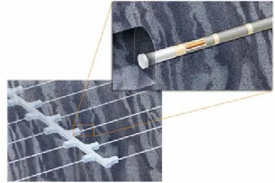
Figure 2.2 The KBS-3 concept with horizontal waste deposition drifts extending from operational niches cut into in the side of a main tunnel. The expanded view shows several supercontainers in a deposition drift, separated by bentonite ‘distance blocks’.
Figure 2.3 The components of the supercontainer in the KBS-3H repository system. The steel cylinder, or liner, is perforated so that the bentonite buffer can expand through the holes and fill the space around the supercontainer.
The repository depth and host rock environment are assumed to be the same for both vertical and horizontal concepts (SKB 2004, R-04-42). The waste, cast iron insert, copper canister and desired density of the saturated bentonite buffer are also the same in both the KBS-3V and KBS-3H systems (SKB 2004, R-04-42). We assume that the repository access tunnels (Figure 2.1) are of similar design for the two concepts, but we have not found an explicit statement of this from SKB.
Key aspects of the KBS-3H design that differ from the KBS-3V design are:
• Repository and backfill volumes: The total volume of tunnels to be
excavated and subsequently backfilled in a KBS-3H repository could be considerably smaller than for a KBS-3V repository. This means that the costs for excavating and backfilling a KBS-3H repository could also be significantly smaller.
• Supercontainer: In the KBS-3H system, the copper canister would be
incorporated within a supercontainer prior to emplacement in the deposition drift. The supercontainer would comprise an outer liner of perforated 8 mm-thick stainless steel, the bentonite buffer, and the copper canister and its contents. The steel liner is perforated so that the bentonite buffer can expand through the holes as it hydrates and swells to fill the space in the drift around the supercontainer.
• Horizontal deposition drifts: In the KBS-3H system, horizontal deposition
drifts would extend for up to 300 m from niches cut into the side of a main tunnel. The KBS-3H deposition drifts are assumed to have a diameter of 1.85 m, slightly greater than the 1.75 m-diameter KBS-3V deposition holes. A concrete plug would be used to seal the open end of each deposition drift. • Distance blocks: In the KBS-3H system, several (perhaps as many as 30)
supercontainers would be placed in each deposition drift, and the supercontainers would be separated by bentonite distance blocks. The ‘reference’ KBS-3H design described in SKB (2004, R-04-42) indicates a distance between neighbouring supercontainers along the deposition drifts of ~3 m. This figure was derived from preliminary thermal calculations made using data on the thermal power of the spent fuel, decay rates, the thermal conductivity of the rock, and an assumed distance between deposition drifts of 40 m (see Section 3.2.1).
3 Differences Potentially Significant to Repository
Performance
This section identifies and discusses issues where the differences between the KBS-3V and KBS-3H designs are potentially significant in terms of repository operation and/or its post-closure performance, and might, therefore, warrant further analysis and regulatory scrutiny. The focus is principally on long-term performance, but operational issues are also discussed because details of operations will determine the initial state for analyses of post-closure repository performance, and because the differences in repository behaviour relating to the differences between the KBS-3V and KBS-3H designs may be most marked during the period leading to repository closure and relatively soon afterwards.
For convenience, the various post-closure issues are discussed under headings that reflect the principal processes involved and their effects (Thermal, Hydrological, Mechanical, Chemical, and Biological), but it is recognised that there are significant couplings between many of the various THMCB processes. Section 4 discusses the issue of how the differences in design may affect the analysis of repository performance and safety.
Cross-references are provided to relevant items on SKB’s list of Internal Processes (see Appendix 1 of SKB 2004, R-04-32). The discussions centre on processes that may affect the fuel, insert and canister, the buffer, and the geosphere close to the repository excavations. The list and analysis of FEPs (features, events and processes) presented as part of the SR-Can Interim documentation (SKB 2004, R-04-32) would need to be extended to cover some additional features of the KBS-3H design, such as the supercontainer liner.
3.1 Operational
Issues
The following points identify operational issues associated with implementing the KBS-3H design:
• Straightness/accurate boring of deposition drifts: SKB (2004, R-04-42)
recognises that successful emplacement of supercontainers in 300 m-long drifts requires that the deposition drifts will have to be bored with a high degree of straightness and accuracy. The gap between the outer part of the 5.5 m-long supercontainer and the walls of the deposition drift is designed to be just 42.5 mm (SKB 2004, R-04-42). Within the constraints of the reference KBS-3H design, it would not be desirable to increase this gap to accommodate a greater tolerance for the drift boring operation because of the need for the bentonite within the supercontainer to swell outwards through the perforated liner and seal the drift with a sufficiently high swelling pressure (see Section 3.2.3).
• Waste handling and emplacement: According to SKB, the supercontainer
would be assembled in an underground reloading station at repository level and used for transporting the waste to the deposition drift. Little information is provided on (i) the procedure or method to be used for supercontainer
assembly, and (ii) the temperature of the canister at the time of supercontainer assembly and any necessary period of cooling before assembly. An assembled supercontainer would be 1.675 m in diameter and would weigh approximately 45 tons (SKB 2004, R-04-42). The larger size and heavier mass of the supercontainer to be handled and emplaced in the KBS-3H system (as compared to the size and mass of a filled copper canister in the KBS-3V repository) represents an increased technical challenge for waste handling, but this may be offset to some extent by the greater degree of radiation shielding provided by supercontainer, which may simplify handling.
• Water management: Owing to its size and mass, SKB suggests that the
supercontainer would be moved along the deposition drift using a water cushion system. A water cushion system is favoured over an air cushion system because trials of air cushion systems revealed difficulties relating to the need for high air pressures and consequently high system power consumptions and heat outputs (SKB 2004, R-04-42). The use of a water cushion system, however, introduces an additional requirement for the deposition drift not to be exactly horizontal, but to rise consistently along its length, at a slope of approximately 2° from the horizontal, so that water from the system can flow back towards the drift entrance and be suitably managed. Another aspect of operational phase water management recognised by SKB is that the deposition drifts may intersect water-bearing fractures that require grouting. SKB (2004, R-04-42) suggests that ‘since a repository based on the
KBS-3H design has a smaller total excavated volume, the leakage of ground water into the horizontal deposition drifts should be less and easier to control than...in KBS-3V’, but this argument is not necessarily correct. The effects on
repository operation (and possibly also on long-term performance) of intersecting water-bearing fractures that are difficult or impossible to seal effectively by grouting, might in fact be relatively greater in the KBS-3H system because a greater length of deposition drift could be affected by each flowing fracture. Viewed in this context, the greater length of the horizontal deposition drifts makes the KBS-3H layout less flexible as a design than the KBS-3V system in which it would be potentially feasible to locate individual deposition holes away from any sub-vertical major flowing fractures.
Further consideration is given to the potential effects of water inflow in Section 3.2.2.
3.2 Post-Closure
Issues
3.2.1 Thermal Issues
SKB has prescribed a maximum temperature for the canister surface of 100°C (SKB 2004, R-04-42). This design constraint is applied to both the KBS-3V and KBS-3H repository designs, and is an important factor in determining the spacing of the waste canisters or supercontainers, and the spacing of the deposition holes or drifts. In turn, these parameters will influence the subsequent analysis of long-term repository
Section 2.2.1 of the SR-Can Interim Process Report (SKB 2004, R-04-33) describes the processes that will influence the transfer of heat away from the waste canisters, summarises several detailed studies aimed at modelling the thermal evolution of the KBS-3V repository, and describes the handling of relevant processes and associated uncertainties in the SR-Can interim performance assessment for the KBS-3V repository design. These studies indicate that engineered barrier system will experience the highest temperatures during the first few (10 to 20) years after waste emplacement.
SKB (2004, R-04-32) lists the following FEPs which will influence the transfer of heat away from the waste canisters and which may be sensitive to the differences between the two repository designs:
• Fuel/cavity in canister.
- 2.3.2 Radiation attenuation/heat generation. - 2.4.1 Heat transport.
• Cast iron insert and copper canister.
- 3.3.1 Radiation attenuation/heat generation. - 3.4.1 Heat transport.
• Buffer.
- 4.3.1 Radiation attenuation/heat generation. - 4.4.1 Heat transport.
• Geosphere.
- 10.4.1 Heat transport.
Thermal calculations for the KBS-3H repository design need to take account of the larger diameter of the deposition drifts (as compared to the KBS-3V deposition holes), of the presence of the steel liner, and of the gaps that will initially be present in the system between the host rock and the steel liner, between the steel liner and the bentonite, and between the bentonite and the canister.
Initial thermal calculations for a KBS-3H repository have been conducted by Hökmark and Fälth (2003). Hökmark and Fälth’s (2003) assessment of drift spacing involved combining a numerical simulation of heat transport away from a main ‘drift of interest’ with the solution to an analytical expression for heat transport away from neighbouring drifts, which were represented as continuous line heat sources. This approach has been verified by comparison with calculations by other workers (e.g., Ikonen 2003) and is fit-for-purpose as long as the ratio of distance block length to drift spacing is small. Hökmark and Fälth’s (2003) results suggest that the length of the distance blocks between the supercontainers could be in the range 3.05 m (for a
drift spacing of 40 m) to 5.35 m (for a drift spacing of 25 m). The range of possible lengths for the distance blocks is, thus, rather large.
Setting the length of the distance block to be the same as the length of the supercontainer might simplify emplacement operations because the same procedures and equipment could then be used when emplacing the blocks and the supercontainers. Simplifying operations in this way might also bring cost savings. Keeping the length of the distance block equal to that of the supercontainer (or less) would also ensure that the current thermal modelling approach, in which the deposition drifts are represented as continuous linear heat sources, was applicable. At this stage, SKB’s thermal analyses have not taken into account possible additional complexities that might result from different rates of buffer swelling at different locations along a deposition drift, but the magnitude of these effects may be small and will depend on the amount of water inflow and the rate of buffer swelling that occurs during the heating phase (see Section 3.2.3).
Uncertainties identified by SKB for further study included (Hökmark and Fälth, 2003):
• How close the repository system can be allowed get to the 100°C design limit. For repository systems in low conductivity rocks where high temperatures may develop, reducing the margin used by Hökmark and Fälth (2003) would bring the required canister spacing down significantly.
• The thermal properties of the gaps initially present between components of the engineered barriers in the KBS-3H system. Experimental measurements of the emissivity of the copper surface were recommended by VTT (see SKB 2004, TR-04-42, page 49 and Ikonen 2003). Some measurements of copper emissivity have been made by Uppsala University but no further measurements are proposed in SKB’s forward programme (SKB 2004, TR-04-21, page 165).
• The initial power of the waste. Raising the power from 1,545 W/canister to 1,837 W/canister means that the spacing must be increased by about 5 m for a high-temperature case.
• The temperatures inside the canister and the thermal expansion of the cast iron insert and the copper casing. It was suggested that the KBS-3H design may be more favourable than the KBS-3V design because the initial contact area between the cast iron insert and the copper canister is larger in the horizontal situation (SKB 2004, R-04-42).
Further analyses of the thermal evolution of a KBS-3H repository are presented in POSIVA Report 2003-11 (Ikonen 2003). The results from POSIVA’s analysis (Ikonen 2003) are similar to those obtained by SKB. POSIVA (Ikonen 2003) also noted that because the thermal diffusivity of the rock is low and the heat released from the canisters is spread into the surrounding rock volume quite slowly, the most important and sensitive parameter in the calculations was the thermal power of the
efficient way to decrease repository temperatures would be to reduce the mass of spent fuel per canister or lengthen the cooling time of the spent fuel before disposal. In conclusion, SKB has identified the key factors that will determine the thermal evolution of a KBS-3H repository, has conducted appropriate modelling studies, and is in the process of optimising the KBS-3H design.
The overall heat input to the repository system is the same for the two design variants and the total volume of rock being heated may be a defining characteristic of the system. Viewed over the entire repository, the KBS-3H arrangement represents a slightly thinner plane than the KBS-V arrangement. To achieve similar a heating effect the horizontal spacing between the waste containers and/or deposition drifts in the KBS-3H case may need to be slightly larger than the horizontal spacing between the KBS-3V vertical deposition holes and/or tunnels. However, the total length of excavation for the two designs may be similar, as indicated by SKB.
The smaller excavation volume of a KBS-3H repository as compared to a KBS-3V repository seems to relate primarily to the use of longer deposition drifts, which have significantly smaller cross-sections than the KBS-3V deposition tunnels, although this effect is offset to some extent because the KBS3-H deposition drifts are slightly larger in diameter than the KBS-3V deposition holes.
SKB’s forward programme includes on-going development of thermo-hydro-mechanical models supported by experimental work aimed at gathering key data (SKB 2004, TR-04-21). SKB’s forward programme on the thermal evolution of the repository seems appropriate.
3.2.2 Hydrological Issues
SKB has identified a range of FEPs related to fluid flow; SKB Internal Process numbers 2.5.1, 4.5.1, 4.5.2, 4.5.3, 4.5.4, 4.7.12, 10.5.1, 10.5.2 (SKB 2004, R-04-32). The following paragraphs focus on key FEPs that may influence water and gas flow in the KBS-3H system.
Water flow
For both the KBS-3V and KBS-3H designs, water flow into the deposition holes or drifts will take place mainly through fractures and will contribute to the wetting of the buffer. However, if the flow is localised by fractures that carry more water than the swelling bentonite can adsorb, there will be a water pressure in the fracture acting on the buffer. Since the swelling bentonite is initially a gel, which increases its density with time as the water goes deeper into the bentonite, the gel may be too soft to stop the water inflow. The results may be piping in the bentonite, formation of a channel and a continuing water flow and erosion of soft bentonite gel (SKB 2004, R-04-33). SKB (2004, R-04-42) describes several experiments into the piping and erosion phenomena that might occur in the KBS-3H repository. The results from these initial experiments are not particularly favourable. Key conclusions drawn from the results of laboratory tests into the piping and erosion phenomena were that (SKB 2004, R-04-42):
• Very low water pressure is required to cause piping and erosion at constant water pressure (2–4 kPa).
• Very little water flow is required to cause piping and erosion at constant water flow (less than 0.001 l/min).
• The processes are complicated with many variables and dependencies.
• The hydraulic function of the rock is very important. In this regard key features are the size and abundance of flowing fractures that intersect the deposition drifts, and the effectiveness and durability of any cement grout used to seal such fractures before supercontainer emplacement.
• The distance plugs are expected to seal the drift and function as intended but only if rates of water inflow are low enough so that erosion does not reduce the density, and as long as the final swelling pressure is higher than the water pressure. At such low rates of water inflow it may take years for the distance blocks to seal the drift.
A key conclusion drawn from the results of some initial full scale sealing tests was that it will not be possible to rely solely on the swelling of the bentonite distance blocks to seal the 2–4 cm gap at the top of the drift. The design of the system would need to be modified, either by reducing the thickness of the gap or by using an alternative means of sealing SKB (2004, R-04-42).
In conclusion, SKB has identified the key factors that may influence the hydrological evolution of a KBS-3H repository, and SKB’s forward programme rightly includes small-scale and full-scale piping and erosion tests specifically aimed at the KBS-3H design, as well as quantitative modelling of colloid generation during buffer erosion (SKB, TR-04-21, page 222). However, based on the reviewed materials it is not easy to see why the future experiments will necessarily provide more favourable results that contradict those already obtained.
If piping and erosion cannot be avoided, then there is the potential for the creation of longer pathways through the buffer in the KBS-3H system than in the KBS-3V system. There is clearly uncertainty regarding the amount to which the perforated steel liner may act to prevent such pathways from extending into the interior of the supercontainer towards the canister. Close to the supercontainers, therefore, any extensive sub-horizontal pathways caused by piping and erosion might be expected to occur close to the corroded steel liner and/or in the narrow annular region between the host rock and the liner. Within the distance blocks, pathways caused by piping and erosion might extend more readily towards and through the centre of the drift. The contacts between the distance blocks and the supercontainers might also act as initial weak points where pathways could form.
There is also a relatively greater chance in the KBS-3H system that hydrological connection could be established between two (or more) flowing fractures in the host rock via pathways in the buffer.
It may be relatively more difficult to ensure that the KBS-3H deposition drifts are located so that they are sufficiently far away from major flowing fractures for their entire length. The intersection of a deposition drift or a series of deposition holes with a horizontal fracture set could be particularly problematic.
For both designs, locating the deposition drifts/holes in ‘good quality’ low permeability rocks with few major flowing fractures would seem to be the answer but a sufficient supply of water is required along the entire length of the drift to enable relatively even swelling of the bentonite.
The representation of such flows and features in performance assessment is considered in Section 4.
Gas flow
Hydrogen gas formation due to supercontainer corrosion (see Section 3.2.4) introduces a complex set of two-phase flow issues. Gas may form bubbles or larger accumulations, possibly along the top of the KBS-3H deposition drift or in the canister. The presence of the gas may influence water saturations and flows. It is also possible that particulate radionuclides could be transported with the gas phase. Particulates tend to accumulate at the gas-water interface (e.g., Bennett et al. 1998). SKB recognises that various gas flow and transport issues need to be taken into account (SKB 2004, R-04-42) but provides almost no details of what analyses are envisaged. SKB (2004, TR-04-21) provides some further information, on the types of results obtained recently from experiments on gas transport in bentonite, on the scope of SKB’s involvement in two EC projects (Gambit and Gasnet), and on SKB’s on-going Lasgit experiment, which is due to be completed in 2007/8. While these activities are useful in that they are addressed at understanding and modelling gas flow in the buffer, they do not appear to cover the issues related to supercontainer liner corrosion or insert corrosion in the KBS-3H layout. For example, scoping calculations of the total potential amounts of gas that could be generated by liner corrosion might be expected. In the KBS-3H system there may be an increased need to develop a two-phase flow description of repository re-saturation (see Section 4).
3.2.3 Mechanical Issues
SKI (2004, Report 2004:46) presents analyses of several possible mechanical effects that might affect the near-field of a KBS-3V repository. The relevant processes correspond to SKB Internal Process number 4.6.1 (SKB 2004, R-04-32). The effects considered were vertical settlement of the canister, swelling of the bentonite, and tectonic movements in the bedrock. The analyses pointed to vertical settlements of less than 10 cm, potentially countered by upward movement of the canister due to bentonite swelling not exceeding 10 cm. Only tectonic movements of the bedrock were assessed as having the potential to cause plastic strain in the canister (SKI 2004; 2004:46).
• the response of buffer/canister system to shear loads from the rock, and;
• the likelihood of shear movements, given the probability of postglacial faults causing secondary movements in fractures that intersect deposition holes, suggest that canister failure due to shear movements of rock fractures intersecting deposition holes can not be entirely ruled out for potential postglacial earthquakes, which may occur tens of thousands, to hundreds of thousands of years after repository closure (SKB 2004; TR-04-11; Hedin, 2005). If, as seems likely, most fractures at the investigated sites are (sub)vertical, there may be a greater chance of a horizontal KBS-3H deposition tunnel being affected by movement on such a fracture in response to post-glacial faulting, than a vertical KBS-3V deposition hole.
SKB is conducting further research on the potential impacts of post-glacial faulting, particulary in the area of the mechanical behaviour of the geosphere (SKB 2004; TR-04-11), and has suggested that if this canister failure mode cannot be shown to be sufficiently unlikely, then canister design modifications might have to be considered (Hedin 2005). We suggest, however, that if canister failure by this mechanism cannot be ruled out, then instead of moving straight to reconsidering the design of the canister, alternative solutions might be sought (e.g., relating to the location of deposition holes or tunnels relative to fractures or taking greater credit for the properties of the geosphere to the extent that this is possible). Also, there may be need for dialogue on what should represent the ‘design-basis’ earthquake, as it would not seem reasonable to design the canister to withstand a worst conceivable earthquake.
In the KBS-3H design, the bentonite buffer is required to swell outwards through the perforated steel liner and seal the deposition drift around the supercontainer. The distance blocks are also required to swell and, thereby, seal the deposition drift along their length.
Uneven swelling of the buffer due to localised ingress of water to the deposition drift might tilt individual supercontainers or push them to one side (or up or down) so that they move away from the centre of the deposition drift. SKI’s International Peer Review Team noted that there were several aspects of the integrated near-field evolution model presented in SKB’s SR-Can interim assessment (e.g., SKB 2004, R-04-11) that gave cause for some concern. One of these was that because the transient saturation of the buffer was not included in the performance assessment calculations there were questions as to the adequacy of the treatment of possible inhomogeneities in buffer density and swelling, etc (SKI 2005, Report 2005:02). The magnitude of swelling effects will need to be considered in conjunction with an assessment of the possible water inflows, particularly associated with fractures (see Section 3.2.2). When considering swelling effects in the KBS-3H system, it will also be necessary to evaluate the potential cumulative effects of swelling in the direction along the deposition drift, and to consider the rate of such ‘along-drift pushing’ in comparison with the schedule for filling and sealing the deposition drifts, and the strength of the concrete plugs.
Concerned about the potential for piping and erosion of the bentonite buffer and distance blocks (again see Section 3.2.2), a NAGRA-ENRESA-NUMO review panel (Snellman 2004) suggested that the gap initially present around the supercontainers and distance blocks might be filled with bentonite pellets. Although the use of bentonite pellets would potentially help to increase buffer density and swelling pressure, trials would be necessary to assess the practicability of emplacing the pellets within the narrow deep annular slots currently envisaged around the supercontainer and the distance blocks. Such trials could include the use of instrumentation (e.g., pressure sensors) to monitor the development of swelling pressure for performance confirmation purposes (see SKI 2004, Report 04:49). If it became necessary, however, to rely on pellets (or some other type of backfill) outside the supercontainer, then some of the proposed benefits of the supercontainer concept would have been lost.
In summary, SKB has identified a range of issues that will influence the mechanical evolution of a KBS-3H repository and has already conducted some relevant small-scale experiments into the wetting of the buffer in this system (SKB 2004, TR-04-21, page 213-214). SKB’s RD&D programme includes a considerable range of new activities under the title ‘Integrated studies - THM evolution in unsaturated
buffer’ (SKB 2004, TR-04-21, pages 211-216), but it is not always possible to see in
detail how each technical issue will be addressed.
Some of the issues will be considered during SKB’s proposed full scale demonstration test of the KBS-3H design at Äspö (see SKB 2004, 42, Section 5 and TR-04-21, page 216) and SKI will need to review and assess in detail the results and interpretations made from this important test.
3.2.4 Chemical and Biological Issues
The main chemical and biological differences between the KBS-3V and KBS-3H designs relate to the introduction of the steel liner in the horizontal supercontainer system. To take account of the steel liner in the KBS-3H design, SKB would need to extend the FEP list included in the SR-Can Interim reports (SKB 2004, R-04-32) and include new FEPs for the liner equivalent to Internal Process number 3.7.1 for the canister. It would also be necessary to re-evaluate the FEP analysis for the buffer to take account of its interactions with the liner.
Supercontainer corrosion
The steel liner will corrode gradually on contact with water. Early aerobic corrosion is likely to give way fairly quickly after the drift is sealed to anaerobic corrosion. Anaerobic corrosion of steel under reducing redox conditions produces hydrogen gas and iron oxides. The rate of corrosion will be affected by a range of factors, including the composition of the steel, the prevailing conditions (e.g., temperature), the potential of the steel, the amount and composition of any pore water present, and the nature of the corrosion process (whether general corrosion or localised, e.g., pitting corrosion, and whether there is any effect of microbially-induced corrosion).
As an example, in the Belgian system for the disposal of spent fuel and high-level waste, a particular concern relates to the possible role of chloride, sulphide and thiosulphate in promoting corrosion of the steel supercontainer liner. In the Belgian setting, thiosulphate is formed as a result of sulphide (e.g., pyrite) oxidation, and enhanced levels of dissolved thiosulphate have been observed in water samples collected from the Belgian underground research laboratory at Mol (De Cannière et
al., 2005). Currently the corrosion lifetime of the liner in the Belgian supercontainer
system is estimated as being in the range from a few years to several hundreds of years, but further research is needed to fill gaps in data relating to the potential role of chloride, sulphide and thiosulphate in steel corrosion under repository conditions (Wickham et al., 2005).
The iron corrosion products (e.g., magnetite) will occupy a larger volume than the un-corroded steel liner, and may have several effects: the corrosion products could provide sites for the sorption of radionuclides, could form a discontinuous layer within the buffer that acts as a weakness, and/or could provide a locus for water flow. Dissolved iron may interact with the bentonite and affect its properties, for example by lowering the potential swelling pressure. Relatively few data are available with which to quantify the potential effects of iron interactions with bentonite, and SKB has identified the need for further study of these processes (SKB 2004, R-04-42). SKB’s suggestion to consider information from natural analogues is sensible, but natural analogue data will probably need to be supported by data from laboratory studies.
SKB’s RD&D Programme also indicates that scoping calculations for KBS-3H concerning the influence of extreme cases where the steel container either doubles its volume or disappears completely due to corrosion show that the buffer can be designed so that both extremes result in a density and a swelling pressure that lie within the required values (SKB 2004, R-04-42, page 211). However these scoping calculations are not presented in detail and no reference to them is provided. SKI should consider reviewing these scoping calculations in detail.
Insert corrosion
Corrosion of the insert will begin if water enters the canister. The rate of insert corrosion will depend on a similar range of factors to those that will control the rate of liner corrosion (see above). Most of the factors will not depend on canister orientation and are, therefore, likely to be equally valid in both the KBS-3V and KBS-3H systems. There could potentially, however, be differences between the KBS-3V and KBS-3H designs in terms of the effects of gas generation and accumulation, which might affect the amount of water in contact with the insert and the rate and extent of corrosion. This topic is discussed further in Section 4.
Assessments of the KBS-3V and KBS-3H designs may also need to differ in terms of the scenarios analysed for nuclear criticality. It would, for example, seem necessary to take account of the differences in the potential geometry of the materials inside the canister as the waste and insert degrade. Figure 3.1 illustrates degraded conditions within a horizontally emplaced spent fuel canister that have been considered within
the US spent fuel disposal programme. SKB’s 2004 RD&D programme foresees no further work on criticality.
Figure 3.1 Illustration of degraded conditions within a horizontal spent fuel canister (Massari and Gottlieb 1998).
Cement-bentonite interactions
Other chemical effects that could be important in the KBS-3H system relate to the interaction between the bentonite buffer and any grouts that may be used to seal fractures in the host rock that intersect the deposition drift. The NAGRA-ENRESA-NUMO review panel recommended the use of so called ‘low-pH’ cement grouts (Snellman, 2004). Low-pH grouts are formulated so that they contain low alkali metal contents and generally have no free portlandite. They therefore condition, or buffer, pore waters to lower pH values than, for example, grouts made with Ordinary Portland Cement (OPC). Waters with lower pH values tend to have less deleterious effects on clay minerals, including bentonite.
According to SKB’s RD&D programme, at least one of the deposition tunnels in the KBS-3H full scale test will be sealed with a plug based on low-pH cement (SKB 2004, TR-04-21, page 124), and SKB is cooperating with NUMO and POSIVA on low pH cement research as well as co-sponsoring a PhD and two post-doctoral studies in this area (2004, TR-04-21, page 118).
4
Performance and Safety Assessment
Performance assessments of the KBS-3H system will need to take due account of the range of effects discussed in Section 3. Consideration will, in particular, need to be given to the following combinations of effects, which may be of relatively greater importance in the KBS-3H system than in the KBS-3V system analysed in previous performance and safety assessments (e.g., SKB 1999, TR-99-06; SKB 2004, TR-04-11):
• Canister evolution.
• Near-field flow and transport.
• Gas generation, accumulation and transport.
The following subsections discuss each of these areas in more detail.
In addition, it will be necessary to re-assess the potential likelihood and consequences of future human actions (such as drilling a borehole) that may affect the repository. For example, in comparison with a KBS-3V repository, vertical boreholes drilled after the withdrawal of control over the repository might be more likely to intersect the waste in a KBS-3H repository because the total area of spent fuel potentially exposed to drilling is greater but any particular drill-string would pass through a reduced thickness of spent fuel.
4.1 Canister
Evolution
SKB considers a canister to have failed when the copper shell has been penetrated, i.e. when there is an open connection between the interior and the exterior of the copper shell. The basic failure mode of canisters is due to corrosion in which penetration of the copper shell occurs where the shell thickness is reduced due to initial welding defects (SKB 2004, TR-04-11, p 257). According to SKB, the average number of failed canisters increases linearly with time, as determined from weld defect statistics, and with the concentration and transport properties of the corroding sulphide impurities in the buffer.
The evolution of a failed canister is complex and depends on a number of factors. Water is likely to enter the canister, causing corrosion of the cast iron insert and hydrogen gas generation. The build-up of gas pressure in the canister could be considerable and could lead to the suppression of further water entry to the canister and cause gas release through the buffer.
As corrosion proceeds corrosion products occupying a larger volume than the corresponding amount of metallic iron will exert mechanical pressure on the copper canister, potentially leading to an expansion of the original defect in the copper shell. The corrosion also causes a weakening of the cast iron insert, making the canister more vulnerable to applied pressure. This could also lead to an increase in the size of defects. The evolution of the canister will also be influenced by external factors like
In the SR-Can radionuclide transport calculations (SKB 2004, TR-04-11), the canister interior was assumed to possess no transport resistance or sorbing capacity. Rather, as soon as the canister became filled with water, a continuous pathway was assumed to exist between the spent fuel and the exterior, and the canister interior was represented as an inert water volume in which radionuclides were dissolved and could diffuse freely.
Section 12.2.2 of SKB 2004 (TR-04-11) describes several different possibilities for the internal evolution of the canister:
• Base case: Corrosion in filled annulus ceases, tight insert.
• Alternative case I: Corrosion in filled annulus continues, Cu shell expands, bentonite creep relaxation.
• Alternative case II: Corrosion in filled annulus continues, Cu shell expands, bentonite compression.
• Alternative case III: Corrosion in filled annulus ceases, corrosion continues inside insert.
SKB, thus, recognises that there are considerable uncertainties regarding the internal evolution of a failed canister. Conceivable outcomes range from situations where the full isolation potential is essentially maintained, to those where a water pathway is established within thousands of years and the initially small damaged area expands to a larger region in tens or hundreds of thousands of years.
SKB’s RD&D programme includes experiments in which miniature canisters, complete with inserts but with defective copper shells, will be deposited in boreholes drilled through water-conducting fractures in the Äspö HRL. The experiments are planned to continue for five to ten years and are aimed at increasing understanding of how corrosion in the gap between the copper shell and cast iron insert may develop (SKB 2004, TR-04-21, page 192). It is not clear whether these experiments include study of canisters emplaced horizontally, or whether the results would be available in time for the forthcoming licence reviews.
In performance assessments of the KBS-3V design, the canister weld and any defects in the weld were assumed to be near the top of deposition hole, with the implication that gas generated within the canister from corrosion of the insert could escape upwards. In performance assessments of the KBS-3H design, SKB will need to consider the location of defects in the canister weld after waste emplacement, because fluid flow in and out of the canister and radionuclide release will depend on whether the hole in the canister weld is at the top, at the side or at the bottom. For example, if the defect was near the floor of the deposition drift, gas might accumulate within the upper part of the canister and force any water that had entered back out through the defect. Over time the evolution of water supply to the interior of the canister, of corrosion and of gas generation could, thus, be rather complex. In reality, the location of defects will not be known, but it may be possible to use statistical methods to support assumptions regarding canister orientation for performance and safety assessment purposes.
4.2 Near-Field Flow and Transport
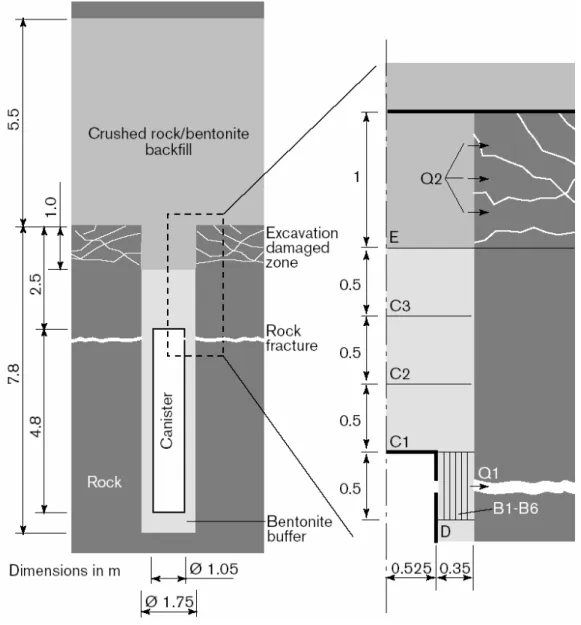
Figure 4.1 depicts the canister, deposition hole and backfill in a KBS-3V repository and shows how such a system was modelled in the SR-Can performance assessment (SKB 2004, TR-04-11) using the COMP23 code.
Figure 4.1 SKB’s modelling representation of the near-field for a KBS-3V repository. The figure illustrates the model used in the SR-Can interim report (SKB 2004, TR-04-11) and shows the compartments B1-B6, C1-C3 and E used in the COMP23 model. The transport paths, Q1, to a fracture, and Q2, to the excavation damaged zone are also shown. (There was also a minor EDZ around the deposition, but this is not shown in the figure.)
Two main transport pathways from the near-field were included:
Q1 A fracture intersecting the deposition hole at the vertical position of the canister lid.
Q2 An excavation damaged zone, EDZ, in the floor of the deposition tunnel. In the earlier SR 97 performance assessment (SKB 1999, TR-99-06) two additional pathways were modelled, but only Q1 and Q2 gave significant contributions.
The number of fractures intersecting a deposition hole and the properties of these fractures were determined statistically based on a discrete fracture network description of the rock (see SKB 2004, R-04-34). If more than one fracture intersected a deposition hole then the transport capacities of the several fractures were added and assigned to the single Q1 fracture modelled by COMP23.
Performance assessments of the KBS-3H design will have to take account of the different geometry of the near-field and to do this it is probable that changes will need to be made to the PA code and/or to the model compartments used. The summation of fracture properties made in the previous performance assessments may need to be reconsidered because of the greater length of the KBS-3H deposition drifts than the KBS-3V deposition holes and the consequent likelihood of each deposition drift intersecting several fractures.
It may be more realistic to consider radionuclide transport (potentially by both advection and dispersion) in channels or zones of enhanced apparent diffusivity and hydraulic conductivity running along the deposition drifts through the buffer and connecting flowing fractures in the host rock. These channels or zones could be formed as a result of several processes, including, piping, erosion, heterogeneous swelling of the buffer, liner corrosion, and partial sealing of channels.
A performance assessment based on such a conceptual model might be seen as being more realistic, and the results of such an analysis would not necessarily be greater in terms of calculated release from the near-field or dose. The results would depend on many factors, including the number of canisters assumed to have failed and their orientation within the deposition drift, as well as the magnitude of any water flow. Dialogue is probably necessary to determine whether such a calculation case should be considered to be part of the ‘main scenario’, a ‘less probable scenario’ or a ‘residual scenario’ (see SKI 2005, Report 2005:02).
4.3 Gas Generation, Accumulation and Transport
SKB acknowledges that understanding of the mechanisms behind gas migration through water-saturated bentonite is incomplete. At a certain pressure, the bentonite will fracture and allow the gas to pass through. In SR 97 (SKB 1999, TR-99-06) this pressure was assumed to be the sum of the swelling pressure and the hydrostatic pressure. The SR-Can interim assessment (SKB 2004, TR-04-11) took account of more recent experimental data that suggests that the entry pressure for gas into bentonite could be substantially higher than was assumed in SR 97.
SKB assumes that fractures generated by the gas will stay open as long as there is sufficient gas pressure, and that when gas production ceases the fractures are likely to close and seal. SKB notes that although high gas pressures can be expected in the near-field, and contaminated water may be pushed out by the gas under certain conditions, gas transport is not expected to lead to an increased hydraulic conductivity of the buffer (SKB 2004, TR-04-11). Therefore gas generation, accumulation and transport has not so far been modelled within the performance assessment consequence calculations themselves.
In the KBS-3H repository system, the presence of the steel supercontainer liner will mean that there is the potential to generate greater total amounts of hydrogen than in the KBS-3V system. It is also likely that the maximum rates of hydrogen production in the KBS-3H system will be higher than in the KBS-3V system because the surface area of steel and iron available for gas generation reactions (i.e., the area that may come into contact with water) will be greater. Also there is the potential for greater connection and flow of gas along the KBS-3H deposition drifts. It is, therefore, questionable whether future performance assessment calculations for the KBS-3H system can justifiably avoid taking explicit account of gas generation and two phase flow.
5
Conclusions and Recommendations
There are many similarities between the KBS-3V and KBS-3H designs. Uncertainties are associated with both of the designs and, when compared, both possess relative advantages and disadvantages.
SKB has identified many of the key factors that will determine the evolution of a KBS-3H repository. SKB has plans for research and development work in many of the areas where the differences between the KBS-3V and KBS-3H designs could be significant in terms of repository performance.
With respect to the KBS-3H design, key technical issues are associated with: 1. The accuracy of deposition drift construction.
2. Water inflow to the deposition drifts from fractures in the host rock and the ability to seal such fractures.
3. The ability of the buffer and distance blocks to seal the deposition drifts. 4. Piping and erosion of the bentonite buffer.
5. Supercontainer liner corrosion and interactions with bentonite. 6. Evolution of processes and materials within failed canisters. 7. Gas generation and flow.
Of these, the most important issues are probably the interrelated issues of water inflow from fractures and buffer performance (Issues 2, 3 and 4), and the evolution of processes and materials within failed canisters (Issue 6).
Although issues 1 to 7 represent potentially important uncertainties for the KBS-3H repository design, the most important of them (Issues 2, 3, 4, 6) also apply to the KBS-3V design (although possibly to a lesser degree). There are also additional uncertainties associated with the KBS-3V design, such as the ability of the backfill to achieve its performance requirements in that system (SKI 2004, Report 2004:49). Performance assessments of the KBS-3H system will need to take due account of the range of effects discussed in Section 3, including the key technical issues. Consideration will, in particular, need to be given to the following combinations of effects, which may be significantly different and potentially of relatively greater importance in the KBS-3H system than in the KBS-3V system:
• Canister evolution. The location of a defect in the canister once emplaced in the KBS-3H repository - whether up, down or at the side - and the consequent influence on fluid flow in and out of canister and radionuclide release. The amount of water that enters the canister will influence the amount of insert corrosion and radionuclide release. The potential for corrosion of the insert
will affect the scenarios to be considered during assessments of nuclear criticality.
• Near-field flow and transport. Water flow and radionuclide transport in pathways running along the deposition drifts through the buffer and connecting flowing fractures in the host rock.
• Gas generation, accumulation and transport. The transport and possible accumulation of gas generated from the corrosion of the supercontainer liner and the cast iron insert, and the effects of gas on water flow.
With respect to the KBS-3H design, an important component of RD&D programme for SKI to review and assess is SKB’s programme of ‘Integrated studies - THM
evolution in unsaturated buffer’ (SKB 2004, TR-04-21, pages 211-216), including
SKB’s proposed full scale demonstration test of the KBS-3H design at Äspö.
SKI should continue dialogue with SKB to ensure that the objectives and specifications for work in SKB’s forward RD&D programme are clearly defined and appropriately targeted, not only at technology demonstration but also at the key issues and uncertainties that will affect performance and safety assessment.
6 References
Bennett, D.G., Crawford, M.B., Wickham, S.M. and Kessler, J. (1998) Multiphase-Flow and Colloid Transport in Total System Performance Assessment, In: Proc. Eighth Annual Int. High Level Radioactive Waste Management Conf. (Las Vegas, 11 - 14 May 1998), American Nuclear Society, La Grange Park, IL and American Society of Civil Engineers, New York, NY.
De Cannière, P., De Craen, M., and Wang, L. (2005) The Concentration of Thiosulphate in an Oxidized Boom Clay Porewater. SCK Technical Note, LWA-TN-11.
Hökmark, H., and Fälth, B. (2003) Thermal Dimensioning of the Deep Repository – Influence of Canister Spacing, Canister Power, Rock Thermal Properties and Nearfield design on the Maximum Canister Surface Temperature. SKB TR-03-09. Svensk Kärnbränslehantering AB.
Hedin, A (2005) EBS Feedback from SR-Can, Presented at the OECD Nuclear Energy Agency Workshop on Engineered Barrier Systems, La Coruña, Spain. August 24-26, 2005.
Ikonen K. (2003) Thermal Analyses of a KBS-3H Type Repository, POSIVA 2003-11.
Massari, J.R. and Gottlieb, P. (1998) Criticality Potential of Commercial PWR SNF in a Degraded Waste Package. In: Proceedings of the Eighth International Conference on High-Level Radioactive Waste Management. American Nuclear Society, pp. 627-629.
SKB (1999) Deep Repository for Spent Nuclear Fuel. SR 97 – Post Closure Safety. SKB TR-99-06, Svensk Kärnbränslehantering AB.
SKB (2004) Interim Main Report of the Safety Assessment SR-Can. SKB TR-04-11, Svensk Kärnbränslehantering AB.
SKB (2004) RD&D Programme 2004: Programme for Research, Development and Demonstration of Methods for the Management and Disposal of Nuclear Waste, Including Social Science Research. SKB TR-04-21, Svensk Kärnbränslehantering AB.
SKB (2004) Interim FEP Report for the Safety Assessment SR-Can. SKB R-04-32, Svensk Kärnbränslehantering AB.
SKB (2004) Interim Process Report for the Safety Assessment SR-Can. SKB R-04-33, Svensk Kärnbränslehantering AB.
SKB (2004) Interim Data Report for the Safety Assessment SR-Can. SKB R-04-34, Svensk Kärnbränslehantering AB.
SKB (2004) KBS-3H. Summary Report of Work Done During Basic Design. SKB R-04-42, Svensk Kärnbränslehantering AB.
SKI (2004) Near-Field Mechanical Analysis of Radioactive Waste Canister i Deep Repository, SKI Report 04:46, Stockholm, Sweden. ISSN 1104-1374.
SKI (2004) Performance Confirmation for the Engineered Barrier System: Report of a Workshop at Oskarshamn, Sweden, 12-14 May 2004, SKI Report 04:49, Stockholm, Sweden. ISSN 1104-1374.
SKI (2005) International Peer Review of Swedish Nuclear Fuel and Waste Management Company’s SR-Can Interim Report. SKI Report 05:02, SSI Report 2005:02, Stockholm, Sweden. ISSN 1104-1374, ISSN 0282-4434. 2005.
Snellman, M. (2004) Expert Review of the KBS-3H Design and the Preliminary Safety Assessment. R&D Report 2004-02, Posiva Oy.
Wickham, S.M., Crawford, M.B., and Bennett, D.G. (2005) Belgian Supercontainer Design for HLW and Spent Fuel Disposal - Evaluation of the Reference Design. GSL Report 0460-5.
S T A T E N S K Ä R N K R A F T I N S P E K T I O N
Swedish Nuclear Power Inspectorate
POST/POSTAL ADDRESS SE-106 58 Stockholm BESÖK/OFFICEKlarabergsviadukten 90 TELEFON/TELEPHONE +46 (0)8 698 84 00 TELEFAX +46 (0)8 661 90 86
ski@ski.se