2012:39
Technical Note
Review of Engineering Geology and Rock
Engineering aspects of the construction
of a KBS-3 repository at the Forsmark
site – Initial Review Phase
Author: Erik Eberhardt
SSM perspektiv Bakgrund
Strålsäkerhetsmyndigheten (SSM) granskar Svensk Kärnbränslehantering AB:s (SKB) ansökningar enligt lagen (1984:3) om kärnteknisk verksamhet gäl-lande uppförande, innehav och drift av ett slutförvar för använt kärnbränsle och av en inkapslingsanläggning. Som en del i granskningen ger SSM konsul-ter uppdrag för att inhämta information i avgränsade frågor. I SSM:s Techni-cal Note-serie rapporteras resultaten från dessa konsultuppdrag.
Projektets syfte
Uppdraget är en del i SSM:s granskning av aspekter inom Ingenjörs-geologi och Bergteknik i SKB:s ansökan om slutförvaring för använt kärnbränsle i Forsmark. Uppdraget avser granskning av integriteten för bergmassan som omger det tilltänkta KBS-3 slutförvaret med fokus på uppförande av anläggningen och dess konsekvenser för det initiala till-ståndet samt utvecklingen av förhållandena i närfältet. Kommentarer ges om teknikerna för bergmassans kartering och karakterisering, anlägg-ningens layout, borrning, sprängning, bergutschaktning samt injektering i kristallina bergarter.
Författarnas sammanfattning
Övergripande tycker granskarna att den geomekaniska datan insamlad och konsoliderad hittills är imponerande i mängd och kvalité. Insamlad data har integrerats i sammanlänkade analyser för att kunna studera slutförvarets utveckling under uppförande och drift. Dock finns det ett antal osäkerheter gällande data och analyser som är oundvikliga när man hanterar geologiska material. En insats har gjorts för att förstå påverkan och fortplantning av osäkerheter på analyser och projektering. Däremot finner granskarna att den största bristen i rapporteringen är avsaknandet av ett konsekvent sätt att hantera nivån av tilltro för olika slutsatser som är grundläggande för valet av projekterings förutsättning-ar. Ytterligare farhågor utöver datan samt dess tolkningstydlighet är:
• Utmaningar resulterande från motstridiga krav från å ena sidan snäva toleranser under uppförande och drift samt å andra sidan den geologiska variabiliteten och osäkerheten som förekommer på flera skalor.
• Medan tillräcklig detaljeringsnivå samt tilltro erhålls för parame-trarna gällande de dominerande bergarterna finns det fortfarande utrymme för utökad datainsamling eller tolkningsmöjligheter för mindre frekventa men förekommande bergarter i slutförvarsvolymen. • Det finns farhågor om att kriteriet för att godta placeringen av
depositionshålen (EFPC) inte tar hänsyn till interaktionen mellan spjälkning och befintliga sprickor i berg. Konsekvensen skulle kun-na vara ett större bortfall av deponeringshålspositioner än förväntat. •
Betydande osäkerheter finns angående de initiala bergspänning-arna. Trots att detta är förväntat för djupa anläggningar som slut-förvaret, är ett mer konservativt antagande nödvändigt för sprid-ningen av de förväntade bergspänningar som använts för analysen
• Observationsmetoden föreslås som metod för hantering av ut-föranderisker. Emellertid finns det behov av att förtydliga hur avvikelser från det förväntade utfallet kommer att hanteras samt huruvida metoden kommer att underlätta för den prompta anpass-ningen av projekteringen till oförväntade förhållanden.
Projektinformation
Kontaktperson på SSM: Flavio Lanaro Diarienummer ramavtal: SSM2011-3641 Diarienummer avrop: SSM2011-4336 Aktivitetsnummer: 3030007-4017
SSM perspective Background
The Swedish Radiation Safety Authority (SSM) reviews the Swedish Nu-clear Fuel Company’s (SKB) applications under the Act on NuNu-clear Acti-vities (SFS 1984:3) for the construction and operation of a repository for spent nuclear fuel and for an encapsulation facility. As part of the review, SSM commissions consultants to carry out work in order to obtain in-formation on specific issues. The results from the consultants’ tasks are reported in SSM’s Technical Note series.
Objectives of the project
This project is part of SSM’s review of SKB’s license application for final disposal of spent nuclear fuel at Forsmark and covers issues of Engine-ering Geology and Rock EngineEngine-ering. The assignment concerns review of the integrity of the rock mass surrounding a KBS-3 repository with focus on the construction and its effects on the initial state and performance of the near-field conditions. Review comments concerning the techniques of rock mass characterization, facility layout, drilling, blasting, withdrawal and grouting in crystalline rocks are also provided.
Summary by the authors
In general, the reviewers find that the level of geomechanics data col-lected and synthesized to date has been impressive in scope and high in quality. The data collected has been incorporated into interlinked analyses concerning construction and operational performance of the repository. There are a number of uncertainties in the data and subsequent analyses that are unavoidable when dealing with earth materials. An effort has been made to understand the impact of propagation of these uncertainties th-rough the analysis and design process. The reviewers find, however, that the main shortcoming of the reporting is a lack of coherent structure required to understand the relative reliability of the conclusions central to the design premises. Major concerns beyond data and interpretive clarity include:
• Challenges posed by conflicts between very tight construction and operational tolerances and the geological uncertainty that is likely to create geometric variability at different scales.
• While significant detail and confidence exists for the main rock types expected, there is room for additional data or interpretation concerning less common but likely rock types within the reposi-tory footprint.
• There is a concern that the rejection criterion for the Deposition Holes (EFPC) may not adequately incorporate the interaction of spall damage and existing fractures and that the rejection rate may be higher in practice than proposed.
• Significant uncertainty exists with respect to the in-situ stresses. While this is to be expected for deep projects such as this, con-servatism is required at this stage with respect to adopted ranges for stress within the context of EDZ (Excavation Damage Zone) generation around excavations and deposition holes.
• The Observational Method is proposed to deal with uncertainties. There is a need to be clear about how deviations will be dealt with and whether this approach will facilitate adequate and timely ad-justments to the design as deviations from expected conditions are encountered.
Project information
2012:39
Author:
Review of Engineering Geology and Rock
Engineering aspects of the construction
of a KBS-3 repository at the Forsmark
site – Initial Review Phase
Erik Eberhardt and Mark Diederichs
Fisher & Strickler Rock Engineering LLC, Radford, VA, USA
This report was commissioned by the Swedish Radiation Safety Authority (SSM). The conclusions and viewpoints presented in the report are those of the author(s) and do not necessarily coincide with those of SSM.
Contents
1. Introduction ... 1
2. Main Review Findings ... 3
2.1. Gaps/Omissions ... 3
2.2. Need of Clarifications by New Submissions ... 3
2.3. Need of Clarifications by Discussion ... 5
2.4. Further Review ... 6
2.5. Independent analyses ... 7
3. Scope of the Initial Review Phase ... 9
3.1. Assigned SKB Reports for Review ... 9
3.1.1. Mandatory ... 9
3.1.2. Recommended ... 9
3.2. Covered Review Topics ... 10
4. Findings of the Initial Review Phase ... 11
4.1. Rock Mass Mapping and Characterisation ... 11
4.1.1. Site Geology, Deformation Zones and Geological Uncertainty ... 11
4.1.2. Thermal Properties and Spalling Strength ... 16
4.1.3. Observational Method ... 19
4.2. In Situ Stress State ... 21
4.3. Excavation-Induced Damage and Spalling ... 25
4.4. Layout, Excavation Techniques and Construction Sequencing ... 29
4.5. Constructability of the Deposition Holes ... 33
4.5.1. Geometrical Tolerances ... 33
4.5.2. Bottom Hole Plate ... 35
4.6. Grouting ... 36
4.7. Shotcrete and Reinforcement ... 38
4.8. Investigation and Performance Verification During Construction ... 40
APPENDIX 1 ... 43
APPENDIX 2 ... 47
1. Introduction
This Technical Note is a revised version of that submitted on the 25th of June, 2012. This review covers the integrity of the rock mass surrounding a KBS-3 repository for spent nuclear fuel with focus on the construction and its effects on the initial state and performance of the near-field conditions. Specifically, the engineering geology and rock mechanics are analyzed concerning the techniques of rock mass characterisation, excavation and grouting in crystalline rocks. The layout and stability of the excavations in relation to the geological conditions are reviewed, together with any issues arising from the layout and geometrical tolerances of the repository, need for rock reinforcement, and excavation-induced damage (EDZ) and spalling (excluding thermal-induced). Also reviewed are the assessment of the in
situ and induced stress fields as well as the need for rock mechanics testing and
monitoring during construction of the repository.
In general, the reviewers find that the level of geomechanics data collected and synthesized to date has been impressive in scope and high in quality. In addition, the data collected has been incorporated into interlinked analyses concerning
construction and operational performance of the repository. There are a number of uncertainties in the data and in the subsequent analysis that is unavoidable when dealing with earth materials. An effort has been made to understand the impact of propagation of these uncertainties through the analysis and design process. The reviewers find, however, that the main shortcoming of the reporting to date is a lack of coherent structure to maintain a clear picture of this propagation and to understand the relative reliability of the conclusions central to the design process (i.e. occurrence of subordinate rock types, expected rock stresses, expected rock behaviour, rock thermal properties, sufficiency of the rock volume for disposal). In most cases this is really an issue of clarity rather than actual oversight.
Major concerns beyond data and interpretive clarity include:
Challenges posed by conflicts between very tight construction and operational tolerances and the geomechanical uncertainty that is likely to create geometric variability at different scales.
While significant detail and confidence exists for the main rock types expected, there is room for additional data or interpretation concerning less common but likely rock units within the repository footprint.
There is a concern that the rejection criterion for the Deposition Holes may not adequately incorporate the interaction of spall damage and existing fractures and that the rejection rate may be higher in practice than proposed.
Significant uncertainty exists with respect to the in situ stresses. While this is to be expected for deep projects such as this, conservatism is required at this stage with respect to adopted ranges for stress within the context of EDZ generation around excavations and deposition holes. The ranges selected for further analysis should be widened to account for the impact of larger stresses, within the range suggested by the original data, and a range of directional stress ratios.
The Observational Method is proposed to deal with uncertainties. There is a need to be clear about how deviations will be dealt with and whether this approach will facilitate adequate and timely adjustments to the design as
both moderate and fundamental deviations from expected conditions are encountered (i.e. extended occurrence of rock spalling, large water in- flows, significant stress anomalies, branching structure of some deformation zones).
2. Main Review Findings
2.1. Gaps/Omissions
Potential issues examined for which we could not find sufficient details in the SKB reports reviewed include:
1. There does not appear to be a Deposition Hole rejection criterion that considers a non-persistent fracture intersecting a Deposition Hole that connects with continuous EDZ/spalling along the floor of a Deposition Tunnel (or vice versa). Continuous EDZ should be treated jointly with the fracture intersection scenarios described in the EFPC.
2. The EFPC criteria only allows for fracture extent as mapped, not for the possibility that the fracture may propagate/coalesce during subsequent construction/operation activities in response to further stress changes and increasing rock temperatures.
3. It does not appear that a project cost-schedule risk assessment has been carried out with respect to construction. A qualitative risk assessment is reported with respect to geohazards, however, schedule delays and cost overruns should also be considered.
4. A fully demonstrated testing of the loading of the canisters at full weight and for the buffer geometry/tolerances specified would be required as a proof of concept with respect to constructability. Repeatability of the procedure should be included to determine the percentage of successful completions per attempt.
5. Means to verify conformance to the Design Premises in a construction environment have yet to be developed for a number of the premises. Much will depend on how characterization and monitoring data is implemented during construction. Licensing conditions should consider the limited Quality Assurance (QA) plan included in the License Application.
2.2. Need of Clarifications by New Submissions
Requests to SKB for complimentary information include:
1. The assessment of likelihood of encountering sub-horizontal brittle fracture zones at the repository depth does not appear to be considered in the qualitative risk analysis. This appears to be based on the identification of only three gently dipping deformation zones in the Site Descriptive Model. Clarification is requested as to the resolution of the detection methods used (seismic reflection, single-hole interpretations) with respect to the
minimum sub-horizontal deformation zone detectable.
2. Is the exclusion of Deposition Holes in low thermal conductivity rock included in the Deposition Hole acceptance/rejection criteria? Do the analyses of loss of Deposition Hole positions account for the likelihood of amphibolite lenses occurring more frequently than indicated?
3. What methodology will to be used to reliably characterise less common rock types (e.g. amphibolites lenses, vuggy granite, etc.) in near-field during construction?
4. Clarification is requested as to the mechanism by which the trend of the maximum horizontal stress is interpreted to decrease in gradient at 400 m depth while the trend of the minimum horizontal stress remains linear.
5. Are the stresses measured in boreholes KFK001/DBT1 and KFK003/DBT3, which are located outside the target volume and in FFM04, applicable to the repository volume? How would the stress interpretation change if these data were excluded?
6. Clarification is requested with respect to the conclusion that EDZ, if it develops, will not be continuous. Is the Äspö experiment on which this conclusion is based only applicable to blast-induced damage and not excavation-induced damage resulting from the redistribution of stress and stress concentrations?
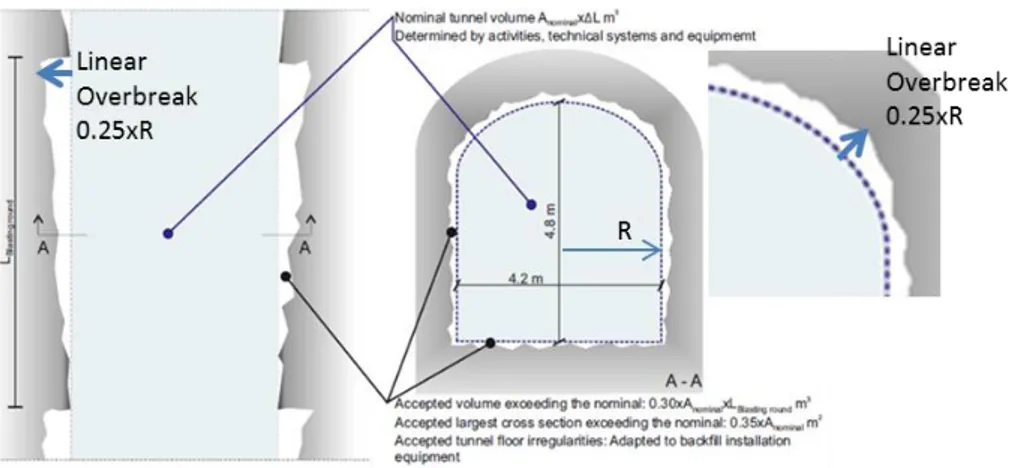
7. Clarification is requested as to the source and basis for the 40 m centre-to-centre separation distance between Deposition Tunnels. This appears to be based on thermal dimensioning. Have stress analyses been performed that consider the influence of excavation sequencing on the development of stresses around/between the Deposition Tunnels and boreholes as the repository is constructed? The analyses reported appear to be based on the stresses between multiple Deposition Holes in a single Deposition Tunnel. 8. Is the 30-35% overbreak limit expressed in the Design Premises for
Deposition Tunnels excessive or incompatible with the requirement to minimize construction damage? Can this be reduced to improve overall quality control? If the specified total volume and section area overbreak limits are maintained, then the reviewers recommend adding a third linear limit to ensure local exceedance is minimized. For example: “Acceptable largest linear overbreak (measured normal to design profile) should not exceed the nominal 0.25×Radius for a circular profile or 0.13×Span for a square profile”.
9. The potential for adverse effects from blasting on the deposition works are accounted for in the repository layout by imposing separation and safety distances. Are similar considerations required for other vibration sources, for example heavy vehicles carrying heavy canisters or hauling waste rock along uneven surfaces?
10. Clarification is requested as to the risk associated with having the ventilation passing from the deposition areas into the excavation areas (as required by the Linear Development Method sequencing) in the event of an accident involving a canister. Is this a potential issue identified in the risk assessment of worker safety or in the development of safety protocols? 11. Clarification is requested as to references in the construction plan reports to
the use of a “TBM”. Is this in reference to a tunnel boring machine? 12. Clarification is requested as to the strictness of the Deposition Hole and
buffer installation tolerances. How critical are they to the safety case? Can they be modified to allow for slightly greater tolerances in order to improve the success rate of installation? If critical, would it be better to install the canister and buffer blocks together as an integrated package allowing the integrity of the full engineered barrier to be verified before installation in the Deposition Holes?
13. Is there a limit on the amount of overbreak that occurs in the Deposition Holes? Should overbreak be included in the Deposition Hole
acceptance/rejection criteria?
14. Clarification is requested as to the role of water inflow acceptance criteria for the different excavation types with regards to the Design Premises and Safety Functions. Similarly, what long-term function, if any, is the grout expected to play.
15. Updates are requested as to the long-term performance of low pH and silica sol grouts together with tested procedures for their handling and use.
16. Clarification is requested as to whether the analysis that concluded spalling is unlikely in the Deposition Tunnels due to their orientation relative to that of the stress field also considered spalling occurring at the tunnel face.
2.3. Need of Clarifications by Discussion
Questions/topics that we believe require a more detailed discussion with SKB include:
1. A detailed discussion regarding plans to develop contingency actions in response to adverse ground conditions, if encountered, may be beneficial. Clarification as to how these will couple Design Premise requirements with worker safety and construction cost requirements should be established. 2. Some of the uncertainties to be managed by the Observational Method will
not be resolved until after construction and operations are well underway (e.g. presence of adverse geology/fractures in the farther reaches of the repository). What are the implications if the rejection ratio of Deposition Holes doubles (triples) in the planned second half of the repository from experiences in the first half of the repository when options for adapting are significantly more limited?
3. A single unified summary of the combined set of measurements, analyses and assumptions (including filtering logic) for the determination of the in
situ stress regime (trends and ranges) needs to be compiled. The current
documentation is complex and leads to the risk of overly confident stress specifications.
4. A discussion would be beneficial regarding the selection of the representative in situ stress and associated ranges (likelihoods) at the repository horizon, as well as provisions for follow-up refinement and implications for design of realistic deviations from this base case (both deviations from the average predicted stress field and local stress anomalies).
5. The distinction and separation of construction damage (CDZ) from stress-induced excavation damage (EDZ) should be discussed, especially with respect to the mitigation and management measures proposed (smooth wall blasting). Also to be considered is the excavation fracture zone (EFZ), also referred to as the highly damaged zone (HDZ).
6. Would installing the canister and buffer blocks together as an integrated package negate the need for the bottom plate? A discussion would be beneficial regarding the sensitivities of the rock/buffer and buffer/canister interfaces with respect to the Design Premises and Safety Functions. 7. A discussion would be beneficial regarding the construction challenges and
implications for worker safety in placing restrictions on the use of shotcrete. Clarification is required as to quantifying what “continuous” means in the context of the Design Premises and how sensitive the reference design for the Deposition Tunnels is to the use of shotcrete. 8. A discussion would be beneficial regarding whether a connected EDZ, in
the event one develops along the walls of a Deposition Hole or in the floor of a Deposition Tunnel, should be treated as a fracture in the same way other large fractures are considered in the EFPC? The treatment of
interconnected fractures that intersect and connect the respective (potential) EDZs of the Deposition Hole and tunnel are not discussed in the EFPC.
2.4. Further Review
Subject matter we suggest requires further review to be carried out during the subsequent Detailed Review phase includes:
1. Further review may be required as to the likelihood and impact of increased width and/or change in position of the major deformation zones on the reference design and underground layout design with respect to increased impact of respect distances within and around the deposition area. 2. Further review may be required as to whether increased tectonic
disturbance and poorer rock mass conditions than accounted for can be expected along the western margin of the repository, and what impact this may have on the constructability and safety of the transport tunnels and ventilation shafts.
3. Further review may be required as to the spalling strengths adopted, the corresponding uncertainty, and whether this should be considered as an uncertainty/geohazard in the qualitative risk analysis of site uncertainties on design. If so, this uncertainty should be considered in tandem with the uncertainty regarding in situ stress.
4. Are there scenarios that the Observational Method won’t be able to react to in a manner that ensures worker safety, project economics and/or the Design Premises being met, and how do the options for adaptation change with different stages of repository construction and operations? Are there operational and post-closure considerations that cannot be tested through the Observational Method?
5. Further review may be required for the currently adopted stress regime at the repository location, including the impact of realistic deviations from this assumption coupled with the uncertainties in strength and stiffness (including local geological heterogeneities).
6. There is limited experience, both experimental and applied, with respect to time-dependent behaviour and long-term evolution of stress-induced brittle fractures. A more detailed and thorough review of the applicability of concepts relating to sub-critical crack propagation, stress corrosion and long-term strength degradation and performance of crystalline rock under sustained compressive loading on stress-induced fractures in the EDZ is suggested.
7. Further review may be required as to how the construction sequence factors into the geohazard risk analysis. The farther extents of the repository will not be penetrated by excavation workings until after 20 years of
construction. How does this impact the overall risk of ensuring the availability of the required Deposition Holes if the geological conditions encountered are more adverse than expected? For example, would the construction of the Main Tunnels, Transport Tunnels and Short-cut Tunnels before proceeding to the construction of the Deposition Areas be a feasible measure to reduce uncertainties and confirm the design assumptions? 8. Further review may be required as to experiences with grouting in
crystalline rock from deep boreholes. The challenges of pre-grouting continuously from surface to the repository depths may force an alternative to raise-boring to construct the ventilation shafts. A risk assessment and cost-benefit analysis should be carried out.
9. Further review should be carried out on the long-term performance of rock bolts, mesh, shotcrete and grout, and what implications their degradation will have on the long-term behaviour and stability of the excavations.
10. Further review should be carried out on the effectiveness and reliability of seismic and radar reflection (or other geophysical techniques) for detecting discriminating fractures in a construction/operations environment.
2.5. Independent analyses
Analyses we recommend be carried out during the subsequent Detailed Review phase include:
1. An independent assessment of the geohazard risks and their likelihood of occurrence may be required. This should possibly include an independent analysis of Deposition Hole rejection scenarios relative to one or more geohazard risks being realized.
2. An analysis of cumulative error propagation is required tracing assumptions and uncertainties in defined stress regime through EDZ assessment and support calculations.
3. Uncertainties in stress and spalling strength may combine to create a likelihood of stress-induced spalling. Quick scoping calculations within the ranges of uncertainties suggest spalling could be significant. This similarly extends to the uncertainties in thermal conductivity and coefficient of thermal expansion, which likewise may combine to increase the extent of thermal spalling.
3. Scope of the Initial Review Phase
This review covers the integrity of the rock mass surrounding a KBS-3 repository for spent nuclear fuel with focus on the construction and its effects on the initial state and performance of the near-field conditions and engineered barriers. Specifically, the engineering geology and rock mechanics are analyzed concerning the techniques of rock mass mapping and characterisation, drilling, blasting, withdrawal and grouting in crystalline rocks.
The layout of the excavation in relation to the geological conditions, excavation techniques and stability problems are also reviewed as items of key interest. This includes the review of any issues arising from the layout and geometrical tolerances of the KBS-3 repository, need of reinforcements, Excavation Damage Zone (EDZ) and spalling (excluding thermal-induced, as this is covered by another review assignment).
Also reviewed are the assessment of in situ and induced stress fields as well as the need for rock mechanics testing and monitoring during construction of the repository.
3.1. Assigned SKB Reports for Review
Review documents were organized according to: i) primary reports, encompassing those assigned as mandatory, and ii) secondary reports, including reports that were recommended in the review assignment together with other reports representing original sources as cited in the primary reports reviewed. These are listed in detail in Appendix 1. Those specified as mandatory and recommended in the review contract, “Description of Review Assignment of SSM’s Initial Review Phase for SKB’s safety
assessment SR-Site: Engineering Geology and Rock Engineering aspects of the construction of a KBS-3 repository at the Forsmark site”, are listed below.
3.1.1. Mandatory
TR-11-01, SR-Site: 4.1-4.5, 5.6-5.8, 10.2, 10.3. 5, 10.4.3-4, 15.5.12, 15.5.15-19, 15.6.2, 15.6.6-7, 15.7.4 and Errata
TR-10-12, Design and production: 3.5-3.9, 4.7-4.9 TR-10-52, Data report: 6.4, 6.5
TR-10-18, Design, construction and initial state of underground openings TR-09-22, Design premises: 3.3-3.5
TR-10-48, Geosphere process report: 3.1, 4 TR-08-05, Site description: 5, 7
R-11-14, Framework for detailed characterisation for construction and operation
3.1.2. Recommended
R-08-113, Underground Design, Layout and construction plan R-08-114, Underground Design, Grouting
R-08-115, Underground Design, Rock mechanics and rock support R-08-116, Underground Design, Layout D2
R-05-71, Potential underground stability (wedge and spalling) TR-10-21, Full perimeter intersection criteria
3.2. Covered Review Topics
The topics reviewed were based on those specified in the “Description of Review
Assignment of SSM’s Initial Review Phase for SKB’s safety assessment SR-Site: Engineering Geology and Rock Engineering aspects of the construction of a KBS-3 repository at the Forsmark site”. These were then expanded to include several
sub-topics, listed in Table 1, to ensure thorough coverage of the assigned reports.
Table 1:Breakdown of review topics covered in this report.
Review Topics Sub-Topics Rock mass mapping and
characterisation techniques Rock domains and fracture domains Intact rock properties (incl. spalling strength) Rock mass properties
Thermal properties
Use of ‘Observational Method’ In situ stresses Measurement techniques
Interpretation
Validation of proposed stress model Excavation layout in relation to: Geologic conditions
In situ stresses (repository depth) Stability and ground control Excavation techniques Drill & blast
Reaming of Deposition Holes Geometries and tolerances
Excavation induced stresses: 3-D stress analyses and stress distributions Stability (operational safety)
Reactivation of fractures (slip & opening modes) Induced seismicity
EDZ & spalling (excluding thermal) Deposition Holes Deposition Tunnels Shafts and ramps
Overbreak/geometrical tolerances Grouting Pre-grouting (shaft sinking)
Deposition Tunnels Shafts and ramp Shotcrete Ground control
Treatment of overbreak/geometrical tolerances Reinforcement Safety during construction
Long-term performance
Excavation response following support degradation Role of stray materials
Auxiliary structures Bottom plate in Deposition Hole Deposition plugs
Reinforcement of tunnel plugs Construction sequencing Linear development method
Impact of excavation works on engineered barriers Investigation & performance
4. Findings of the Initial Review Phase
Review of SR-Site and the assigned reports for the Initial Review Phase focussed on their clarity and transparency, scientific robustness, data traceability (from site description through to interpretation and modelling), thoroughness in propagating data uncertainties and testing alternative conceptual models, and focus and substance in relation to the Safety Functions, Design Premises, site understanding and constructability of the KBS-3 repository at Forsmark.
Overall, we found the work produced in the reports to be of a high scientific quality. The investigations carried out, methodologies employed and analyses undertaken often push the boundaries of both the state-of-practice and state-of-the art in rock engineering. The documentation is substantial, but still highly accessible in its clarity and readability. Nevertheless, we did encounter several general issues with the documentation. Specifically:
Original data and sources were sometimes difficult to track, due to referencing of a report that references a different report (and so on). This leads to poor traceability of some key arguments. This is particularly true for the in situ stress prediction.
The Design Premises reported in the license application reports are not always consistent (compare TR-09-22, TR-10-16, TR-11-01). The Design
Premises serve to specify the performance requirements of the repository.
Obsolete premises should not appear in the license application.
Secondary reports are cited that sometimes state their findings as being inconclusive but are used in higher level reports (e.g., SR-Site) as being conclusive. Examples include the in situ stress interpretation and analysis of EDZ and spalling potential.
Sparse sample distributions or those with anomalies and outliers are sometimes not thoroughly reviewed (e.g., in situ stress data).
Methods to ensure quality assurance in constructing the reference design too often appear as an afterthought.
These are discussed in the following sub-sections, which provide our review findings for the Initial Review Phase. The review is structured to report the key issues and questions that arise for each of the review topics (§3.2), focussing on aspects related to the engineering geology and rock mechanics that could potentially affect: i) the safety-related Design Premises (primarily based on those reported in TR-11-01), and ii) the constructability of the repository. These are then followed by our recommendations with respect to gaps/omissions, requests for clarification and further detailed review.
4.1. Rock Mass Mapping and Characterisation
4.1.1. Site Geology, Deformation Zones and Geological
Uncertainty
A. Review Comments Related to Design Premises:
Relevant Design Premises discussed in SR-Site (TR-11-01) related to the site geology, rock domains and major deformation zones include:
The repository volume needs to be selected where it is possible to find large
volumes of rock fulfilling the specific Deposition Hole requirements.
Deposition Holes are not allowed to be placed closer than 100 m to
deformation zones with trace length longer than 3 km.
Deposition Holes should, as far as reasonably possible, be selected such
that they do not have potential for shear larger than the canister can withstand. To achieve this, the EFPC criterion should be applied in selecting Deposition Hole positions.
The feedback to these Design Premises suggests that the repository volume and depth selected are adequate (TR-11-01, §15.5.18), and that further detailed investigation during construction will allow for the actual extents of damage zones and splays related to the major deformation zones to be characterized at depth (TR-11-01, §15.5.12). It is also suggested that the EFPC criterion may be superseded by other means to identify the size of fractures intersecting the Deposition Holes if required. Nevertheless, TR-10-21 presents a thorough development and validation of the EFPC. The reviewers are confident that as it is proposed the EFPC is a practical criterion.
The identification of major deformation zones is well constrained by surface mapping and geophysical surveys and further supported by borehole logging, as reported in the Site Descriptive Model (TR-08-05, §5). Several open questions, however, may be posed that could impact the number of available Deposition Holes (due to constraints placed by the Design Premises). These are:
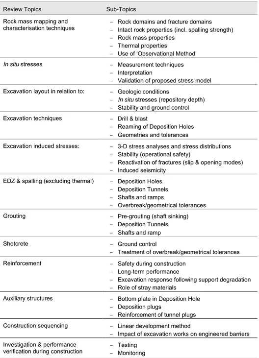
1. Are the surface trace lengths and widths of the major deformation zones representative at depth? The location of the major deformation zones are treated deterministically (R-07-45, §5) but involve projections from surface traces supported by single-borehole interpretations of “possible
deformation zones” (R-07-45, §3.3). These assume constant length, width and planarity with depth (see Stage 2.2 Site Descriptive 3-D Model reported in R-07-45, Fig. 5-12, reproduced here in Figure 1, TOP). However, as also indicated in TR-08-05 (p. 141-142), fault zone architecture typically involves branching, undulating structures whose widths can vary significantly with depth (Figure 1, BOTTOM). This is especially relevant to the WNW-NW sets, which are reported as showing clear evidence of a combined ductile and brittle deformational history (TR-08-05, p. 170). Thus, a significant degree of uncertainty to the location and width of the major deformation zones at the repository level can be expected, which may impact the number of Deposition Tunnels/Holes available in relation to the 100 m respect distance criteria. Uncertainty is acknowledged with respect to the characteristics of the deformation zones at depth (TR-08-05, §5.9.2), however it is not evident that this is considered in the qualitative risk analysis in the underground layout design (R-08-116, §8) where increased width and/or change in position may result in altered respect distances that impact to a higher degree on the deposition area.
2. Could there be more problematic sub-horizontal faults at the repository depth than that assessed and accounted for in the Site Descriptive Model? Three gently dipping deformation zones (ZFMA2, ZFMA8 and ZFMB7) are specified as entering the target volume between 400 and 600 m depth, with two of these occurring along or close to the roof of the repository volume (TR-08-05, p. 148). These zones are reported as showing only
Such features could act as hydraulic conduits, increase the risk of canister shearing, negate large numbers of potential Deposition Holes (based on the EPFC), as well as cause significant construction challenges. Identification of the gently dipping fracture zones is reported to be based on prominent reflectors in the seismic reflection data supported in part by the single-borehole interpretations (TR-08-05, p. 143). This raises the question as to the resolution of the geophysical methods used, as sub-horizontal
deformation/fault zones less than the thicknesses reported (i.e. <6 m thick) could equally be problematic. These would also be difficult to detect through cross-correlation with the single-borehole interpretations. Data bias is reported for the north-eastern half of the regional model with respect to the absence of gently dipping zones (reflection seismic data was not available for this area; TR-08-05, p. 175). The size and variation in intensity of the gently dipping fracture zones are acknowledged as significant uncertainties in the Site Descriptive Model (TR-08-05, p. 175), however, the likelihood of encountering a sub-horizontal fracture at the repository level does not appear to be considered in the qualitative risk analysis for the underground layout design (R-08-116, §8). There may be a need to provide provision and contingency for adjusting the vertical elevation of some deposition areas if unfavourable subhorizontal zones are encountered within the horizon or near enough to critically impact
deposition hole acceptance (via the EFPC).
Figure 1:TOP – Steeply dipping deformation zones included in the 3-D local model, stage 2.2.
Zones marked in red have a ground surface trace length > 3 km and those in green are between 1 and 3 km. BOTTOM – 3-D geometric model for a brittle deformation zone inside the north-western targeted part of the tectonic lens at Forsmark (TR-08-05, Fig. 5-26). Attention is drawn to the variable character of the zone along the two borehole intersections.
B. Review Comments Related to Constructability:
The focus of SR-Site (TR-11-01) and the Forsmark site description (TR-08-05), with respect to the site geology and its influence on the construction of the KBS-3 repository, concentrate on the two rock domains that define most of the target volume: RFM029 and RFM045. These are well-described with respect to the initial state (TR-11-01, §4) and the geometrical and mechanical characterization model (TR-08-05, §7). Less attention is given to the bounding rock domains and deformation zones, at least with respect to how they may adversely influence the local rock mass conditions and construction. Specifically:
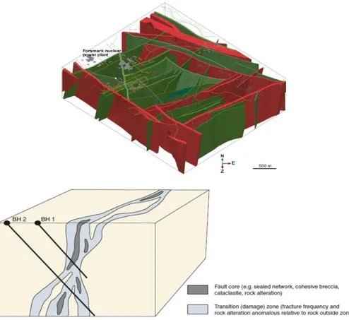
1. RFM012 and RFM044, which are located along the west margin of the target area (Figure 2, TOP), are not discussed in TR-11-01. They are noted briefly in TR-08-05 as being domains that are affected by a high degree of ductile strain (§5.4.4, p. 136). Inspection of the geological data reported in R-07-45 suggests that these domains are associated with major tectonic features that appear to be splays of the Eckarfjärden regional deformation zone. For example, RFM012 is bound by major deformation zones (surface trace lengths >3 km; see ZFMNW1200 and ZFMWNW0123 in Figure 2, BOTTOM). It is likely that these domains will be tectonically disturbed, at least in part, and therefore will be significantly weaker than the rock encountered in RFM029 and that assumed in the various construction reports (see point 2).
2. The layout diagrams for the facility in R-08-116 show that segments of the transport tunnel along its western perimeter will be hosted in these weaker domains (Figure 2, TOP). Other segments are shown as being located along the ZFMWNW0123 major deformation zone (Figure 2, BOTTOM). R-08-116 (p. 37) cites findings in R-08-83 as showing that the rock mass quality of the deformation zones is suitable for locating either the main or transport tunnels. However, relevant sections of R-08-83 (§4.2) do not appear to consider the increased tectonic disturbance to the domains along the western perimeter. Furthermore, whereas a ground type GT4 is specified on p. 61 as applying to the major deformation zones (>3 km), the summary of expected distribution of ground types in the target volume indicates that GT4 will not be encountered (see R-08-83, p. 56). This summary does not appear to agree with the geological data, which suggests that at least some percentage of the transport tunnels will be impacted by poor rock mass conditions related to major deformation zones, specifically
ZFMWNW0123 and ZFMENE0060 (Figure 2, BOTTOM). 3. The layout diagrams for the facility in R-08-116 show that the two
ventilation shafts are to be located near/within areas of weaker rock and higher water inflows related to major deformation zones (>3 km). The western ventilation shaft appears to be located near a fault that offsets the two tectonically disturbed domains noted above, RFM012 and RFM044 (Figure 2, TOP). The eastern ventilation shaft appears to be located near/within ZFMENE0060 (Figure 1, BOTTOM). While there is
operational and sound reasoning for positioning the shafts as proposed, it is not clear that a risk-benefit optimization analysis has been carried out to balance the construction risks associated with shaft sinking and support in these weaker zones versus the need to place the shafts away from the storage areas yet in locations that ensure proper airflow throughout the facility.
4. Note that respect distances are specified for the Deposition Tunnels relative to the major deformation zones, and design aspects related to the layout and locating of the central area likewise considers the adverse influence of the deformation zones. The questions raised here are specific to the transport tunnels and ventilation shafts.
Figure 2: Planned location of the transport tunnels (blue lines) and ventilation shafts (filled
green circles) from Figures 4-10 and 4-15 in R-08-116, superimposed on drawings of the rock domains (TOP) and surface intersection of deformation zones (BOTTOM). Modified from Figures 4-4 and 5-10, respectively, in R-07-45.
C. Recommendations (Category: Clarification/Submission): The assessment of likelihood of encountering sub-horizontal brittle fracture zones at the repository depth does not appear to be considered in the qualitative risk analysis. This appears to be based on the identification of only three gently dipping deformation zones in the Site Descriptive Model. Clarification is requested as to the resolution of the detection methods used (seismic reflection, single-hole interpretations) with respect to the minimum sub-horizontal deformation zone detectable.
D. Recommendations (Category: Detailed Review/Further Review): Further review may be required as to the likelihood and impact of increased width and/or change in position of the major deformation zones on the reference design and underground layout design with respect to increased impact of respect distances within and around the deposition area.
E. Recommendations (Category: Detailed Review/Further Review): Further review may be required as to whether increased tectonic disturbance and poorer rock mass conditions than accounted for can be expected along the western margin of the repository, and what impact this may have on the constructability and safety of the transport tunnels and ventilation shafts.
4.1.2. Thermal Properties and Spalling Strength
A. Review Comments Related to Design Premises:
Relevant Design Premises discussed in SR-Site (TR-11-01) related to the rock strength and thermal properties include:
The buffer geometry (e.g. void spaces), buffer water content and distances
between Deposition Holes should be selected such that the temperature in the buffer is < 100°C.
The feedback to this Design Premise (TR-11-01, §15.5.15) suggests that even when the spatial variability of the rock thermal properties is accounted for, there is an adequate margin to the peak temperature criterion for the buffer (< 100°C). It is further suggested that careful thermal management of the disposal sequence can be used to avoid situations where a canister is deposited in a deposition area where nearby positions were deposited several years before resulting in buffer temperatures that would exceed the peak temperature criterion.
The validity of the thermal dimensioning and expected temperature distribution to which the Design Premise applies is outside the scope of this review. Therefore, the comments/issues discussed here only apply to the thermal properties and their determination (as used in the thermal dimensioning calculations). SR-Site reports a high degree of confidence in the modelled distribution of thermal properties (seeTR-11-01, §4.3.3), pointing to the Site Description Model (TR-08-05) for the reporting of the distribution of modelled thermal conductivities. TR-08-05 subsequently points to R-07-47 and R-08-65 for the respective modelled distribution of thermal
properties for RFM029 and RFM045, respectively. Review comments and open questions related to these reports and others related to the thermal properties are:
1. Thermal conductivity is a temperature-dependent parameter. Values for the different lithologies were obtained using the Transient Plane Source (TPS)
186). A quick check of the thermal dimensioning modelling procedure (R-09-04) suggests that the temperature dependence in the thermal
conductivity was accounted for. TPS values compared reasonably well to those derived using the Self Consistent Approximation (SCA) method (see R-07-47, p. 33 for comparison). Further verification of these values is likely only meaningful once it becomes possible to make in situ measurements. SKB subsequently acknowledges that an alternative method(s) for determining thermal conductivity in situ at a canister-relevant scale is required (R-11-14, p. 65).
2. Variability and heterogeneity of the thermal properties were accounted for stochastically, with distributions being derived for RFM029 and RFM045. However, several comments are made in the reporting of the derivation of these distributions that the largest uncertainty applies to the amphibolites (e.g., R-07-47, p. 6). It should also be noted that rock types involving tonalite (101051) together with diorite dykes, have low thermal
conductivity values similar to the amphibolites (see R-07-47, p. 70) due to their lower quartz percentage. Rock type 101051 appears to be considered in the stochastically derived distributions of thermal properties, but the dykes are not. Thus, the thermal dimensioning does not account for localized pockets of low thermal conductivity that may be associated with dykes, dyke swarms or larger amphibolites lenses. It is not clear if this occurrence in proximity to one or more Deposition Holes should be accounted for in the exclusion criteria. TR-10-18 states as fact that Deposition Holes in rock with low thermal conductivity will not be permitted, resulting in loss of canister positions (p. 35). However, this fact does not appear in SR-Site (TR-11-01) or possibly other higher level documents.
3. The inclusion of the lower conductivity rocks in the stochastic modelling of the thermal properties assumes a certain volumetric percentage of the amphibolites (102017) and the tonalitic varieties of granodiorite to tonalite (101051). It is not clear if the subsequent thermal dimensioning accounts for variations in these percentages that may be higher. Similarly, other distinct rock types (e.g. vuggy granite associated with quartz dissolution; see R-07-45, §3.4.4) do not appear to be considered. The discussion of influence of alteration on thermal conductivity in R-07-47 (§3.3.3) does not include quartz dissolution, which given the dependence of quartz on thermal conductivity, may be of minor significance locally where quartz dissolution occurs.
B. Review Comments Related to Constructability:
Deformation and strength properties for the Forsmark rock types are presented in the site description report, which concludes that there is a high degree of confidence in the properties of the dominant rock types in rock domains RFM029 and RFM045 (TR-08-05, §11.2.6). Similar conclusions are made with respect to the rock mass and fracture properties (TR-08-05, §11.3.5). Remaining uncertainties are reported with respect to the uniaxial compressive strength of the subordinate rock types
(amphibolites and fine-/medium-grained metagranitoid), and up-scaled properties of the fractures. Further issues raised in the review of the rock mechanics properties that may negatively impact construction include:
1. The description of the rock mass and its properties are based on statistical treatments of the data. This adds an element of uncertainty to the influence and possible adverse effects of distinct rock types and other rock mass heterogeneities.
2. The key parameter assessed with respect to spalling potential is the crack initiation stress. Crack initiation values from laboratory testing are considered to be a lower-bound approximation of the in situ spalling strength (TR-07-01, p. 103). This was extended to the spalling analysis reported in Appendix C of R-08-116. It should be noted though, that the laboratory procedure used to determine the crack initiation values, as described in TR-07-01 (§8.3), introduces a significant degree of
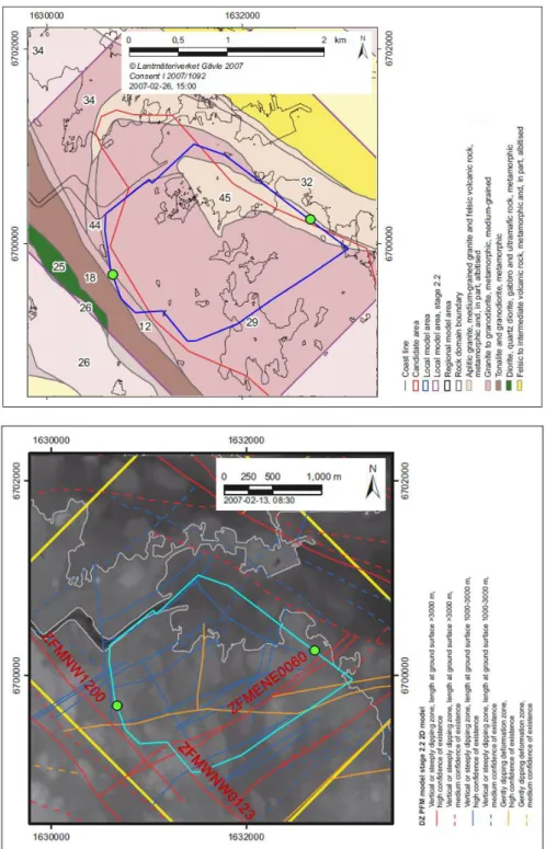
subjectivity and error. The technique is based on plotting strain gauge data from uniaxial compression tests and picking the point of crack volumetric strain reversal, which is calculated from (and therefore partly dependent on) Young’s modulus and Poisson’s ratio values. Apart from the differences in values that may arise from uncertainties in the elastic constants, selecting the point of reversal has an approximate accuracy +/- 25% given the flatness of the minima of the curve and resolution of the stress-strain measurements (Figure 3). As acknowledged in TR-07-01 (p. 103),
determination of the crack initiation stress is not straightforward. Although the uncertainty in the stress field is the dominant uncertainty with respect to spalling potential, should consideration also be given to the impacts of uncertainty in the spalling strengths on design?
Figure 3: Uniaxial compressive test data showing selection of the crack initiation stress value
(dashed line) based on the crack volumetric strain reversal. Note subjectivity (+/- 25% ) in picking the point of reversal due to the flatness on the minima. From Figures 8-10 in TR-07-01.
C. Recommendations (Category: Clarification/Submission): Is the exclusion of Deposition Holes in low thermal conductivity rock included in the Deposition Hole acceptance/rejection criteria? Do the analyses of loss of Deposition Hole positions account for the likelihood of amphibolite lenses occurring more frequently than indicated?
D. Recommendations (Category: Clarification/Submission): What methodology will to be used to reliably characterise less common rock types (e.g. amphibolites lenses, vuggy granite, etc.) in near-field during construction?
E. Recommendations (Category: Detailed Review/Further Review): Further review may be required as to the spalling strengths adopted, the corresponding uncertainty, and whether this should be considered as an uncertainty/geohazard in the qualitative risk analysis of site uncertainties on design. If so, this uncertainty should be
considered in tandem with the uncertainty regarding in situ stress.
4.1.3. Observational Method
The Observational Method is a suitable risk management technique to deal with geological uncertainty during construction. Its implementation requires several actions as outlined in TR-10-18 (§3.2) and Eurocode 7: (i) establish acceptable limits of behaviour, (ii) assess range of possible behaviour, (iii) devise monitoring plan to reveal whether the actual behaviour lies within the acceptable limits, (iv) ensure response time of instruments and data processing is sufficient to allow enough time for intervention, and (v) devise a plan of contingency actions if the monitoring reveals behaviour deviates outside acceptable limits.
A. Review Comments Related to Constructability:
The above noted requirements pose several challenges in ensuring that the
fundamental requirements of stability, tightness and durability of the final repository are met. Several questions/comments can be posed with respect to the
implementation of the Observational Method and relying on it to manage uncertainty related to the rock conditions to be encountered:
1. Contingency actions are required to react to unexpected or more adverse conditions than expected being encountered during construction. This is integral to the Observational Method. However, R-08-116 states that the detailed plans for contingency actions won’t be developed until the next design step (p. 93). It is not clear when this next design step will be taken, but it is critical to assessing the feasibility of the repository. As noted in R-08-116 (§3.6, §8.5.2), possible actions may include the need to develop an alternative layout plan, increase the Deposition Hole spacing, etc. Thus it is conceivable that a series of adverse and unfavourable conditions are encountered that require changes to the layout that may significantly alter the number of Deposition Holes available, or significantly decrease worker safety and increase costs.
2. Several consequences in response to geohazard risk are propagated through a qualitative risk analysis of site uncertainties on the reference design (R-08-116, §8.4). However, the likelihoods of occurrences assigned appear to be weighted towards favourable acceptances of the surface and borehole investigation data as being representative of the rock conditions that will be encountered. For example, R-08-116 suggests that it is:
- Unlikely that there will be deviations from the proposed distribution of the rock types at depth (G2);
- Extremely unlikely that the frequency of long fractures will depart from the predictions of the Geo DFN Model (G3);
- Unlikely that the thickness of minor deformation zones exceeds the estimations in SDM-Site (TR-08-05) (G6);
- Unlikely that the properties of the major deformation zones deviate from the design values (R1);
- Unlikely that the orientation and magnitudes of the in-situ stresses exceed the values in the rock stress model (R2 through R4);
- Unlikely that the geometry of the thermal domains deviates from the model (T1);
- Unlikely that amphibolites and dykes occur more frequently than in the model (T2).
It is this uncertainty and the need to obtain data at depth during
construction that the Observational Method is being applied. In this sense, there is a risk that the likelihoods assigned (R-08-116, §8.3) are not as conservative as reported.
3. A limitation of the Observational Method is if a ground condition is encountered for which there is no contingency action that can be feasibly implemented. What is the impact of a significant deviation from the design response in terms of construction and operation? Are there any issues that are “show stoppers” (that the Observational Method cannot fix)?
4. Several uncertainties are listed in the Site Description Model (TR-08-05) relating to the geology, thermal properties and rock mechanics state, for which the Observational Method is to be used. When will the location and width of the major deformation zones be established at the repository depth? Will invasive investigative drilling be allowed if it doesn’t align with a planned tunnel? How will the 100 m respect distance be imposed if the exact locations of the deformation zones outside the footprint of the repository aren’t known? What if a gently dipping major/minor fracture zone is encountered at the repository depth (one that may be below the detection threshold of the surface geophysics or single-hole
interpretations)? What if the fracture characteristics (size/intensity) based on surface outcrop data are more favourable than those at depth? What if the distribution of rock types/thermal rock classes deviates significantly from the design values? What if the horizontal stress magnitudes are significantly higher than expected? Can the Observational Method react to these open questions in a manner that is safe and economical while still ensuring the Design Functions are met?
5. Similar to the previous comment, uncertainty in the size distribution and size-intensity model for fractures at the repository depth can only be reduced by data collected underground beneath 200 m (TR-08-05, p. 432). Uncertainties in stress magnitudes won’t be reduced until observations and measurements are made during the construction phase (TR-08-05, p. 432). Some of these uncertainties will be addressed during the early stages of construction (e.g. in situ stress). Others, however, may not be resolved until after construction and operations are well underway (e.g. presence of adverse geology/fractures). What are the implications if the rejection ratio
repository from experiences in the first half of the repository when options for adapting are significantly more limited? Note that although it is not included in SR-Site (TR-11-01) as a Design Premise for long-term safety, TR-10-18 includes a Design Premise stating “The repository shall have sufficient capacity to store 6,000 canisters” (p. 20).
B. Recommendations (Category: Clarification/Discussion): A detailed discussion regarding plans to develop contingency actions in response to adverse ground conditions, if encountered, may be beneficial. Clarification as to how these will couple Design Premise requirements with worker safety and construction cost requirements should be established.
C. Recommendations (Category: Clarification/Discussion): Some of the
uncertainties to be managed by the Observational Method will not be resolved until after construction and operations are well underway (e.g. presence of adverse geology/fractures in the farther reaches of the repository). What are the implications if the rejection ratio of Deposition Holes doubles (triples) in the planned second half of the repository from experiences in the first half of the repository when options for adapting are significantly more limited?
D. Recommendations (Category: Detailed Review/Further Review): Are there scenarios that the Observational Method won’t be able to react to in a manner that ensures worker safety, project economics and/or the Design Premises being met, and how do the options for adaptation change with different stages of repository
construction and operations? Are there operational and post-closure considerations that cannot be tested through the Observational method?
E. Recommendations (Category: Detailed Review/Independent Analysis): An independent assessment of the geohazard risks and their likelihood of occurrence may be required. This should maybe include an independent analysis of Deposition Hole rejection scenarios relative to one or more geohazard risks being realized.
4.2. In Situ Stress State
The initial state of stress at the repository level, and its profile from surface, have been proposed based on a combination of in situ stress measurements at depth, a consideration of the tectonic regime and trends, as well as from back analyses of borehole performance (breakouts). This analysis is detailed in R-07-26, R-07-31 and P-07-206, and the results are summarized in R-08-116 (p. 27) reporting the most likely, unlikely minimum and unlikely maximum stress magnitudes and their orientation.
While there is no specific Design Premise directly related to the in situ stress state, the initial stress state represents a key boundary condition and input that impacts the degree of spalling in both the Deposition Tunnels and Holes as well as structural stability (fallout from roof and shear in floor). It is also a controlling factor for shaft constructability and rock reinforcement, as well as the coupled hydro-mechanical behaviour of the fracture systems.
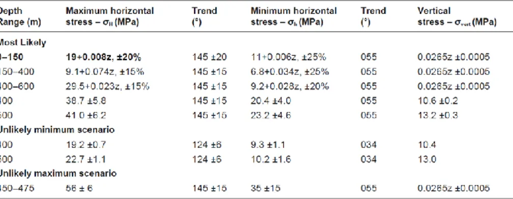
The working ranges for in situ stress for design purposes are reproduced in Table 2 from R-08-116 (§3.4).
Table 2:Stress magnitudes and stress orientations for the three stress models (most likely,
unlikely minimum and unlikely maximum) used for Design Step D2. From R-08-116 (§3.4).
A. Review Comments Related to Constructability:
Questions/comments arising from our review with respect to the initial stress state reported and its determination include:
1. Stresses have been measured at a variety of locations within or near the target area, and directly related to the repository volume. A number of these measurements (in particular those from KFK001/DBT1) have been
discarded in the final interpretation process. This filtering of data is justified in R-07-26 based on a number of arguments including the comparison with other indirect stress estimation techniques such as back analysis of borehole breakout data (§8). As stated in the Site Description report (TR-08-05, p. 215):
“It should be noted that the deepest overcoring measurements from
KFK001 (DBT1) are questionable. The reasons for this are described and discussed in detail in /Martin 2007/, where also established trends in the data sets are presented, expressed as, for example, the mean stress and the ratios between the principal stresses.”
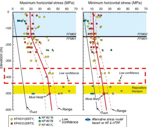
Removal of this borehole from the dataset results in a significant change in the interpretation (see Figure 4). Rejection of this data needs to be more thoroughly justified and seems to be based on the overestimate of vertical stress. While this does justify possible rejection of the data, it is possible that this overestimation of vertical stress (higher than overburden pressure) is due to anisotropic damage in the vertical core resulting in a higher vertical stress estimate (i.e., greater relaxation strains in the overcore in this direction). Such damage would not have the same impact on the horizontal stress estimates. Similarly, there are numerous uncertainties in the
alternative approaches (including estimate of true borehole strength for back analysis of breakouts) that it is unclear as to the justification for exclusion of some of the overcoring data. As such, the in situ stress values are based on a number of unverified (although possibly valid) assumptions, under which the stated “likely” maximum stress (σH) at the target depth
could be underestimated by up to 25 to 35% (i.e., resulting in “likely” horizontal stresses as high as 50-55 MPa instead of the stated 41 MPa). While this higher range is reported, it is taken into account as an unlikely scenario. Note that the implication of higher stresses or more extreme stress
ratios is the inclusion of spalling and/or structural shear. These mechanics do not currently figure in the design considerations.
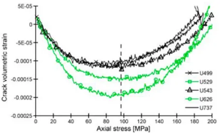
2. What is the mechanism by which the trend of the maximum horizontal stress decreases in gradient at 400 m depth but the trend of the minimum horizontal stress remains linear (see red dashed box in Figure 4). The change in trend at 150 m makes sense as a different fracture domain is being entered (and is reflected in both the maximum and minimum horizontal stress). However, there is very limited justification for the decrease in trend at 400 m in the reports provided. The conclusion is discussed in R-07-26 (§7.2.4) although the reasoning is potentially
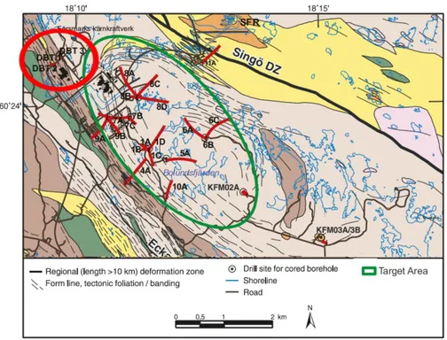
insufficient to justify such a significant diversion from the measured trends. 3. It is unclear whether the stress regime measured in boreholes
KFK001/DBT1 and KFK003/DBT3 are applicable to the repository volume. The Site Description report (TR-08-05) reports these boreholes as being drilled in FFM04 (p. 214), which is situated outside the target volume and involves different rock and fracture domains (see Figure 5). Given the complex regional structural geology, and the influence it can have on the stress field (as seen in the change in trend at 150 m in Figure 4), the applicability of these measurements to the repository volume is
questionable. As shown in Figure 4, these data points represent the majority of the data on which the in situ stress interpretation is based.
4. Is there an issue with the early use of the Borre probe, which was subsequently revised/improved for subsequent measurements? This again applies to the compatibility and reliability of the stress measurement data from KFK001/DBT1 and KFK003/DBT3, which were made using an early prototype of the Borre probe (R-07-26, p. 45).
5. It is unclear how the measurements of Ask et al. (P-07-206) were considered in the final determination of the stress gradient. These were hydrofracture measurements.
6. The final determination of in situ stress is the result of a number of assumptions, simulations, and filtration of (possibly incompatible) measurements. This process must be better summarized in the final documentation with associated justifications clearly and briefly explained, as it is critical to the assignment (and verification) of the “likely” and maximum/minimum “unlikely” scenarios (e.g., as used in the qualitative risk assessment and assessment of potential loss of deposition-hole positions due to spalling reported in R-08-116).
B. Recommendations (Category: Clarification/Submission): Clarification is requested as to the mechanism by which the trend of the maximum horizontal stress is interpreted to decrease in gradient at 400 m depth but the trend of the minimum horizontal stress remains linear.
C. Recommendations (Category: Clarification/Submission): Are the stresses measured in boreholes KFK001/DBT1 and KFK003/DBT3 located outside the target volume and in FFM04 applicable to the repository volume? How would the stress interpretation change if these data were excluded?
D. Recommendations (Category: Clarification/Discussion): A single unified summary of the combined set of measurements, analyses and assumptions (including filtering logic) for the determination of the in situ stress regime (trends and ranges) needs to be compiled. The current documentation is complex and leads to the risk of overly confident stress specifications.
E. Recommendations (Category: Clarification/Discussion): A discussion would be beneficial regarding the selection of the representative in situ stress and associated ranges (likelihoods) at the repository horizon, as well as provisions for follow-up refinement and implications for design of realistic deviations from this base case (both deviations from the average predicted stress field and local stress anomalies). F. Recommendations (Category: Detailed Review/Further Review): Further review may be required for the currently adopted stress regime at the repository location, including the impact of realistic deviations from this assumption coupled with the uncertainties in strength and stiffness (including local geological heterogeneities). G. Recommendations (Category: Detailed Review/Independent Analysis): An analysis of cumulative error propagation is required tracing assumptions and uncertainties in defined stress regime through EDZ assessment and support calculations.
Figure 4: Evaluated in situ stress state at Forsmark, from Figure 7-18 in TR-08-05. Red
dashed box added to highlight depth at which the maximum horizontal stress trend decreases in gradient without a corresponding change in trend for the minimum horizontal stress.
Measurements marked as low confidence (with an X) are overcoring results from KFK001/DBT1.
Figure 5: Map of the Forsmark site showing the locations of the cored boreholes, from Figure
2-10 in R-07-26. Red circle added to highlight locations of DBT1 and DBT3 (stress measurement boreholes) outside the Target Area.
4.3. Excavation-Induced Damage and Spalling
Note that thermal-induced spalling was explicitly not included as part of this review assignment.
A. Review Comments Related to Design Premises:
Relevant Design Premises discussed in SR-Site (TR-11-01) related to excavation-induced damage and spalling include:
Excavation induced damage should not result in a connected effective
transmissivity, along a significant part of the disposal tunnel and averaged across the floor, higher than 10–8 m2/s.
SR-Site (TR-11-01) takes the position that there is ample evidence suggesting that any potential EDZ formed during excavation will be kept below the maximum allowed transmissivity. Furthermore, they point to the same evidence as suggesting that any EDZ that forms will not be continuous (§15.5.16). Issues/comments raised in our review with respect to EDZ and spalling include:
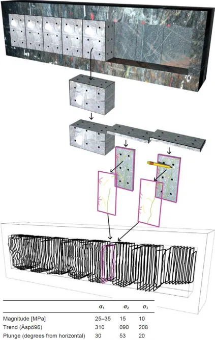
1. The conclusion that the EDZ if it develops is not continuous is based on the conclusions from a large in situ experiment conducted at Äspö, as reported in R-09-39. This experiment was conducted under a stated in situ stress field with σ1 = 25-35 MPa, oriented at 30 degrees from horizontal. A tunnel
was excavated using drill and blast techniques, from which samples were cut from the tunnel wall (Figure 6). First, it should be noted here that these test conditions are based on lower stress conditions than those expected at Forsmark. More importantly though, the samples were cut from the tunnel