IN THE FIELD OF TECHNOLOGY DEGREE PROJECT
MEDIA TECHNOLOGY
AND THE MAIN FIELD OF STUDY
COMPUTER SCIENCE AND ENGINEERING, SECOND CYCLE, 30 CREDITS
,
STOCKHOLM SWEDEN 2018
Container Orchestration in
Security Demanding Environments
at the Swedish Police Authority
CHRISTIAN ABDELMASSIH
KTH ROYAL INSTITUTE OF TECHNOLOGY
Container Orchestration in Security Demanding
Environments at the Swedish Police Authority
MASTER THESIS
Christian Abdelmassih
chrabd@kth.se
Master’s Programme in Computer Science Degree Programme in Media Technology
KTH, Royal Institute of Technology
School of Electrical Engineering and Computer Science
Examined by Prof. Mads Dam
Supervised by Björn Thuresson and Johanna Mannung
In cooperation with the Swedish Police Authority
July 9, 2018
Stockholm, Sweden
The adoption of containers and container orchestration in cloud computing is motivated by many aspects, from technical and organizational to economic gains. In this climate, even security demanding organizations are interested in such technologies but need reassurance that their requirements can be sat-isfied. The purpose of this thesis was to investigate how separation of applica-tions could be achieved with Docker and Kubernetes such that it may satisfy the demands of the Swedish Police Authority.
The investigation consisted of a literature study of research papers and official documentation as well as a technical study of iterative creation of Kubernetes clusters with various changes. A model was defined to represent the require-ments for the ideal separation. In addition, a system was introduced to classify the separation requirements of the applications.
The result of this thesis consists of three architectural proposals for achieving segmentation of Kubernetes cluster networking, two proposed systems to re-alize the segmentation, and one strategy for providing host-based separation between containers. Each proposal was evaluated and discussed with regard to suitability and risks for the Authority and parties with similar demands. The thesis concludes that a versatile application isolation can be achieved in Docker and Kubernetes. Therefore, the technologies can provide a sufficient degree of separation to be used in security demanding environments.
Sammanfattning
Populariteten av containers och container-orkestrering inom molntjänster mo-tiveras av många aspekter, från tekniska och organisatoriska till ekonomiska vinster. I detta klimat är även säkerhetskrävande organisationer intresserade av sådana teknologier men söker försäkran att deras kravbild går att möta. Syf-tet med denna avhandling var att utreda hur separation mellan applikationer kan nås vid användning av Docker och Kubernetes så att Polismyndighetens krav kan uppfyllas.
Undersökningen omfattade en litterär studie av vetenskapliga publikationer och officiell dokumentation samt en teknisk studie med iterativt skapande av Kubernetes kluster med diverse variationer. En modell definierades för att representera kravbilden för ideal separation. Vidare så introducerades även ett system för klassificering av separationskrav hos applikationer.
Resultatet omfattar tre förslag på arkitekturer för att uppnå segmentering av klusternätverk i Kubernetes, två föreslagna systemkomponenter för att upp-fylla segmenteringen, och en strategi för att erbjuda värd-baserad separation mellan containers. Varje förslag evaluerades med hänsyn till lämplighet och ris-ker för myndigheten och parter med liknande kravbild. Avhandlingens slutsats är att en mångsidig applikationsisolering kan uppnås i Docker och Kubernetes. Därmed kan teknologierna uppnå en lämplig grad av separation för att kunna användas för säkerhetskrävande miljöer.
This thesis closes the last chapter of my Degree Programme in Media Technology and Master’s Programme in Computer Science at KTH, Royal Institute of Technology in Stockholm, Sweden. Realizing this thesis has proved to be exciting, enlightening and an invaluable experience. I would like to thank KTH and the Swedish Police Authority for providing an environment to learn and conduct research.
In particular, I would like to express special gratitude towards the following.
Björn Thuresson for being by supervisor at KTH, providing me with an academic perspective and guiding me through the thesis process.
Mads Dam for being my examiner at KTH and ensuring that this thesis has reached the sufficient academic qualification to be published.
Johanna Mannung for proposing the thesis subject, helping me form the method-ology, supervising my research and making me see the bigger picture.
Stefan Eriksson for the technical guidance and the endless discussions on architec-ture, networking and what not.
Walter Thyselius for the frequent conversations on interesting and relevant devel-opments in the security field.
Torbjörn Carlsson for being a sounding board and pointing me in the right direc-tion in various security topics.
Alain Wallström for motivating me with your support and limitless enthusiasm. Liv Larsen for your continuous support and for providing me with the opportunity to realize this thesis at the Authority.
Tom Johansson for proposing the research framework and providing guidance and feedback from an academic perspective.
Julia and Emelie for supporting and accompanying me during the thesis process.
Thank you all, I am deeply grateful for your support.
Contents
1 Introduction 1 1.1 Background . . . 1 1.2 Objective . . . 2 1.3 Research Question . . . 2 1.4 Delimitation . . . 3 1.5 Methodology . . . 3 1.6 Research Gap . . . 4 2 Theory 5 2.1 Virtualization . . . 52.1.1 Hypervisors and ESXi Architecture . . . 5
2.1.2 ESXi CPU and RAM Allocation . . . 6
2.1.3 ESXi Networking . . . 7
2.1.4 Virtual Machine Escape . . . 7
2.2 Containerization . . . 7
2.2.1 Docker Architecture . . . 8
2.2.2 Container Networking Interface . . . 8
2.2.3 Isolation Mechanisms . . . 8 2.2.4 Container Sandboxing . . . 9 2.2.5 Container Escape . . . 10 2.3 Container Orchestration . . . 10 2.3.1 Kubernetes Architecture . . . 10 2.3.2 Kubernetes Networking . . . 13
2.3.3 Pod Scheduling Control . . . 13
2.3.4 Kubernetes API Security . . . 15
2.3.5 Cluster Intrusion Detection . . . 15
2.4 Cluster Networking Solutions . . . 15
2.4.1 Flat Network Topology . . . 15
2.4.2 Overlay Networking and VXLAN . . . 16
3 Result 18 3.1 Solution Objectives Model . . . 18
3.2 Application Classification System . . . 18
3.3 Baseline Architecture . . . 19
3.4 Mitigating Container Escape Risks . . . 20
3.5 Pod Co-location Strategies . . . 21
3.5.2 Other Potential Schemes . . . 23
3.6 Network Segmentation Designs . . . 23
3.6.1 The Cluster History Catalog . . . 24
3.6.2 The Policy-driven Micro-Segmentation . . . 25
3.6.3 The Segmentation Composer . . . 28
3.6.4 The Centralized Firewall Segmentation . . . 29
3.6.5 The Inter-Cluster Firewall Segmentation . . . 31
4 Evaluation 33 4.1 Satisfaction of Objectives Model . . . 33
4.1.1 The Co-location Scheme . . . 33
4.1.2 The Policy-Driven Micro-Segmentation . . . 33
4.1.3 The Centralized Firewall Segmentation . . . 34
4.1.4 The Inter-Cluster Firewall Segmentation . . . 34
4.2 Potential Abuse Scenarios . . . 34
4.2.1 Bypassing the Co-location Scheme . . . 34
4.2.2 Cluster State Corruption . . . 35
4.2.3 Segmentation Corruption . . . 35
5 Discussion 36 5.1 Relevance to Research Question . . . 36
5.2 Separation Approach . . . 36
5.3 Architecture Mindset . . . 37
5.4 Method Criticism . . . 37
5.5 Sustainability and Ethics . . . 38
5.6 Applications . . . 38
6 Conclusion 40
7 Future Work 41
List of Figures
2.1 Comparison of the Virtualization Layers . . . 6
2.2 Overview of the Docker Architecture . . . 8
2.3 Overview of a Kubernetes Cluster . . . 11
2.4 Overview of the Kubernetes Architecture . . . 11
3.1 Overview of the Baseline Cloud Architecture . . . 19
3.2 Comparison of the Virtualization and containerization Layers . . . 20
3.3 Overview of the Separation Flow of Pods . . . 22
3.4 Overview of the Cluster History Catalog . . . 24
3.5 Overview of the Packet Flow in VXLAN-based Clusters . . . 25
3.6 Overview of the Micro-Segmentation . . . 27
3.7 Overview of the Segmentation Composer . . . 28
3.8 Overview of the Centralized Firewall Segmentation . . . 30
The following list contains the most central acronyms used in this thesis. The page number represent the primary occurrence.
BGP Border Gateway Protocol. 16
CNCF Cloud Native Computing Foundation. 2 CNI Container Networking Interface. 8
CVE Common Vulnerabilities and Exposures. 7 DSRM Design Science Research Methodology. 3 IDS Intrusion Detection System. 15
LSM Linux Security Module. 8 OCI Open Container Initiative. 7 OS Operating System. 1
PaaS Platform-as-a-Service. 4
RSIE Required During Scheduling Ignored During Execution. 14 RSRE Required During Scheduling Required During Execution. 14 Seccomp Secure Computing Mode. 8
SELinux Security-Enhanced Linux. 8 VLAN Virtual LAN. 7
VM Virtual Machine. 1
VTEP VXLAN Tunnel Endpoint. 16 VXLAN Virtual Extensible LAN. 16
Chapter 1
Introduction
This thesis is composed of five main chapters followed by the Conclusion and Future Work chapters. This chapter, Introduction, covers the motivation, field and purpose of this thesis as well as its methodology. Chapter 2, Theory, covers the necessary topics to understand the thesis. Chapter 3, Result, present the chosen objectives model, the findings and proposals of the thesis. Chapter 4, Evaluation, compares the proposals with the objectives model. Finally, in Chapter 5, Discussion, argues on the implications of the findings and how they may be utilized for more secure containerization and container orchestration.
1.1
Background
Cloud computing is a field which allows on-demand access to IT infrastructure and com-putational resources such as servers, databases and storage which are offered as a service through the internet [2, 33, 60]. It allows businesses to operate in IT without the high costs of buying hardware and maintaining infrastructure otherwise associated with such field [2, 33, 60]. Currently many actors in cloud computing uses hypervisor-based virtu-alization [5, 64, 95]. By using a hypervisor, a user may create and run Virtual Machines (VMs) which emulates a full computer system through resource allocation of CPU, RAM and disk space [84]. This allows a user to run an Operating System (OS) inside the VM and thus run multiple OS’s on the same hardware.
Virtualization introduces a layer which isolates applications in different VMs from each other and enables applications to execute safely through separation [65]. Further-more, virtualization have matured in usage and have received a considerable amount of contributions to security [84]. Compared to other solutions however, hypervisor-based virtualization can be performance demanding and may bring unwanted overhead [64]. It does not allow the VMs to share resources between each other regardless if the allocated resources are unused. Finally, agile development methodologies have gained traction which has peaked interest in shorter development cycles through Continuous Integration and Delivery [89].
In this climate containerization has gained traction as a challenger to hypervisor-based virtualization [64]. It introduces a layer between the OS and the application. This layer is called container and since it only contains the application and necessary runtimes it is lighter than a VM [64]. Since multiple applications can now be placed on the same OS
as co-located containers containerization is also more cost-efficient than virtualization. This contributes to why Docker, a popular solution for containerizing applications, is being adopted in various fields [35, 64]. With the popularity of containers and the shift in mindset new needs are being fostered in the realm of cloud computing. One initiative which drives this adoption is the Cloud Native Computing Foundation (CNCF). It is an open-source initiative to make cloud-native computing sustainable and universal where cloud-native systems are characterized by being containerized among others [12, 14]. One of their projects which in particular has gained traction, both in community and industry, is Kubernetes, a container orchestration solution for managing, scaling and deploying containers across clusters of nodes [5, 13, 15]. Kubernetes has since release partnered with a large amount of cloud providers and other stakeholders in the IT industry [5, 15]. However, migrating to containers in cloud computing may introduce risks in compari-son with VMs. In environments with high security demand some applications may require a higher degree of separation than others. The key difference in security between VMs and containers in such environments is that containers introduce multiple applications on the same OS which may imply less separation between applications. On the other hand, containers simplify use of agile methods such as DevOps and potential increase to productivity [89]. With this in regard containers spark a cost versus security issue. Since this topic is related to both productivity and economics it interests many parties and businesses operating in IT from developers and system administrators to managers and CEOs.
1.2
Objective
The Swedish Police Authority are interested in using containers and container orches-tration. Before any adoption however, the application isolation must be ensured on the new platform. Specifically, they are interested in the security implications of using Docker containers and orchestration through Kubernetes with respect to the separation of applications in comparison with applications run in VMs managed by the bare-metal hypervisor ESXi provided by VMware.
The goal of the thesis is to gain knowledge in the theoretical and practical implications of using Docker and Kubernetes in environments with high security demands. The goal for the Authority is to gain insight and guidance regarding to which extent they should adopt containerization and container orchestrated solutions.
1.3
Research Question
The focal point for this thesis regard investigation of the following main research question. How can Docker and Kubernetes support the separation of applications for the Swedish Police Authority compared with virtual machines powered by the bare-metal hypervisor ESXi?
CHAPTER 1. INTRODUCTION
1.4
Delimitation
The research question was investigated with the following delimitation in mind.
• No application-layer security is examined since applications are assumed to be vul-nerable.
• The attack surface of the Kubernetes Master is not considered in order to narrow the scope of this thesis.
Additionally, the examined software version of Docker and Kubernetes was 18.03 and 1.10 respectively.
1.5
Methodology
In order to answer the research question Docker and Kubernetes were investigated as a case study in order to design a cluster architecture which satisfies the separation re-quirements of the Authority. To conduct such research in a scientific manner a research methodology was selected followed by a literature study and a technical study.
Research Methodology
Since this thesis falls into the category of Systems Design it follows the Design Science paradigm as described by Hevner, Ram, and College [32]. Due to this the selected methodology for this thesis is Design Science Research Methodology (DSRM) as proposed by Peffers et al. [68]. In short, the methodology is composed of six activities.
1. Problem identification and motivation: Define the main research problem and the need for a solution. Atomize the research problem into parts if needed. This is described in this chapter.
2. Define the objectives for a solution: Define qualitative or quantitative objec-tives such that the solution can be compared to, for example, previous solutions in the field.
3. Design and development: Create the system by, for instance, determining its architecture, model or functionality.
4. Demonstration: Demonstrate how the system solves the problems through exper-imentation or other methods. Since this thesis deals with theoretical architectures the experimentation will be limited.
5. Evaluation: Determine to which extent the system does address the problems through measurement or other suitable means.
6. Communication: Communicate the problem, the systems design and conclusions to relevant audiences.
Following the DRSM as a guideline, the solution objectives as well as the design and demonstration are provided by Chapter 3. The evaluation is given by Chapter 4. Finally, the communication of conclusions and applications by Chapter 5 and Chapter 6.
Literature Study
The primary sources of information consist of literature studies of academic publications and official documentation. The publications were collected through the use of the ser-vices Google Scholar and ResearchGate. Additionally, Primo, an online service offered by KTH Royal Institute of Technology, was used due to its integration with academic databases with it access to non-public academic papers. Examples of relevant keywords used in the search are provided below.
• ESXi VM Escape
• Container Escape Exploit
• Kubernetes Network Segmentation
While the initial search results were used primarily, referenced works were also viewed.
Technical Study
In order to further gain understanding and verify outcomes in Kubernetes several clusters were constructed through kubeadm, a tool which create minimum viable clusters with regard to the Kubernetes Conformance Tests [37, 54]. In addition, clusters of OpenShift Origin, a Platform-as-a-Service (PaaS) which builds upon Kubernetes, were constructed through Ansible, a software which automates server provisioning among others [67].
1.6
Research Gap
The field of application isolation in computing has been researched well before the adop-tion of containers. The first academic papers in the field which are available in Google Scholar were published in the 1990s. Over the years, research has been made in various topics. An example of such research is the work by Czajkowski [18] which target isolation in programming languages as well as the work by Nemati [65] which researches low level execution environments and hardware. However, no academic publication in application isolation seems to exist which examine containerization when used together with orches-tration. In this regard, this thesis is the first academic publication in the field with such scope.
Chapter 2
Theory
This chapter covers the necessary topics to understand the thesis. The Virtualization and Containerization sections describe the technologies and, from an architectural man-ner, how the technologies implement separation towards the host. It focuses on specific software instances, ESXi and Docker respectively. The Container Orchestration section covers the architecture of Kubernetes and other points of interest with regard to secu-rity. Finally, Cluster Networking Solutions cover specific network implementations in Kubernetes clusters.
2.1
Virtualization
Hypervisor-based virtualization, referred to as simply virtualization in this thesis, is a technology that enable computers to run multiple OS’s in parallel by running them in VMs which are managed by a hypervisor [81]. The hypervisor introduces a layer which allows allocation of hardware computing resources such as CPU, RAM and disk space to each VM and thus simulate a computer system [34]. The benefits virtualization provides are, among others, in flexibility, availability and scalability but do also come with drawbacks such as increased overhead [81]. In a report published by FOI, the Swedish Defence Research Agency, the risks of virtualization are analyzed with regard to Swedish Armed Forces [23]. The report concludes that virtualization is a valuable technology even with regard to the security demands of the Armed Forces and that the risks of virtualization may be acceptable in such environments for a set of cases.
Many enterprises which run clouds, public or private, use the bare-metal hypervisor ESXi by VMware [5]. While bare-metal hypervisors are offered by several vendors, the ESXi hypervisor regards the scope of this thesis. The rest of this section covers the architecture of ESXi and its isolation mechanism. In addition, the section includes attacks relevant for the scope of this thesis.
2.1.1
Hypervisors and ESXi Architecture
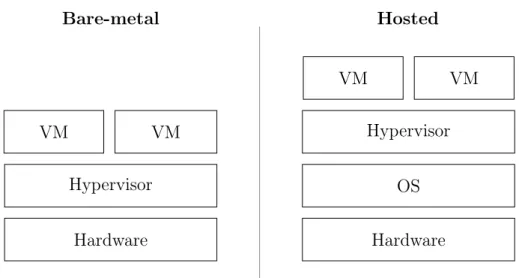
Hypervisors are classified into two categories [27, 64].
• Type-1 or bare-metal hypervisors which run directly on top of the hardware. • Type-2 or hosted hypervisors which require to be run on top of an existing OS.
Hardware Hypervisor VM VM Bare-metal Hardware OS Hypervisor VM VM Hosted
Figure 2.1: Comparison of the layers of Type-1 and Type-2 Virtualization. The Type-2, hosted hypervisor requires an additional OS layer.
A layer-to-layer comparison of the categories is provided by figure 2.1. Since the VMs of bare-metal hypervisors do not run on top of an OS they may utilize computational resources better and may therefore be more suitable for enterprises operating in IT. Hosted hypervisors are on the other hand suitable for personal computing as it allows a user to run multiple VMs on an existing desktop OS after installing a virtualization software.
The kernel is the part of an OS which handles the most critical tasks, for example, process management and resource management [57]. The bare-metal hypervisor ESXi has a non-Linux, non-Unix kernel, the VMkernel, which is dedicated for virtualization [92, 97]. The VMkernel is responsible for many tasks, one of which is to provide the execution environment, the Virtual Machine Monitor, to each VM.
In comparison with hypervisors from other vendors the functionality contained in each virtualization layer may vary. For example, the open source virtualization solution Xen has a special VM which together with the hypervisor manages the guest VMs [99]. With regard to such architectural differences there are many means of achieving Type-1 virtualization.
2.1.2
ESXi CPU and RAM Allocation
ESXi utilizes the Intel VT-x and AMD-V hardware-level technologies to allow a hypervi-sor to provide VMs with direct access to the CPU while maintaining separation between VM instructions [92]. While a virtualized OS runs as privileged, it does so on a layer above the hypervisor preventing it from performing actions which could overthrow the hypervisor. If an OS tries to execute such action, ESXi cuts off the direct CPU access followed by an inspection and, if it is deemed legitimate, emulation of the action. Finally, ESXi returns CPU access to the VM.
For delegation of memory ESXi allocates physical RAM to a VM which its processes may use though a virtualized address space. Before allocating more memory to a VM the hypervisor overwrites all data stored on the RAM before allocation. However Transparent
CHAPTER 2. THEORY
Page Sharing enables VMs to increase efficiency in memory utilization by sharing Memory Pages, continuous memory blocks of static length.
2.1.3
ESXi Networking
Besides the VMkernel the ESXi hypervisor includes a virtual networking layer which is composed of virtual network adapters and virtual switches [91]. It is through the virtual networking layer that the VMs communicate with each other and with outbound hosts. The virtual network can be configured with networking zones to enhance VM separation [90]. For example, an ESXi host could have 3 VMs of which only 1 VM could be accessed from the internet. To further control networking within the ESXi host, ESXi supports Virtual LAN (VLAN) configuration which can be utilized to introduce network segmentation between VMs [91, 92].
2.1.4
Virtual Machine Escape
VM Escape, the act of escaping a VM onto the underlying system, was early demonstrated through the exploit Cloudburst by Kortchinsky [40]. The exploit successfully achieved a VM escape on VMware Workstation, a virtualization solution with a hosted hypervisor. While the specific vulnerability was patched, the additional OS layer required by hosted hypervisors introduce an additional attack surface. This makes the distinction between hosted and bare-metal virtualization solutions essential to security. However, the absence of an OS layer does not make the virtualization security infallible, in connection with the hacking contest Pwn2Own in 2017 a series of critical bugs were discovered which, if exploited, would allow arbitrary code execution in the bare-metal hypervisor ESXi [93, 94]. The four Common Vulnerabilities and Exposures (CVE) labeled from CVE-2017-4902 to CVE-2017-4905 were of such severity that CERT-EU, the European Computer Emergency Response Team, issued an advisory to its bodies and members regarding the vulnerabilities [8].
Besides escape attacks, data could also be extracted through side-channel attacks due to hardware flaws. A recent example of this is Spectre and Meltdown which utilizes speculative execution in CPUs to read privileged memory, memory strictly associated with root privileges [30]. Using this method, a malicious user, with control of a VM, could read data leaked from other VMs residing on the same hardware regardless of the virtualization technology and without the use of escape attacks.
2.2
Containerization
Containerization or OS-level virtualization is a technique where the OS kernel supports multiple isolated user-space environments [5]. In such system the isolated environments are called containers. There are several containerization engines which achieves this through features in the Linux kernel such as LXC. Docker is a software application which uses its own containerization engine, libcontainer, to create containers [28, 56]. In order to standardize the container format, the Open Container Initiative (OCI) was formed by Docker and others to provide specification on, for example, the container runtime [66]. The focus of this section is the architecture and isolation of Docker containers.
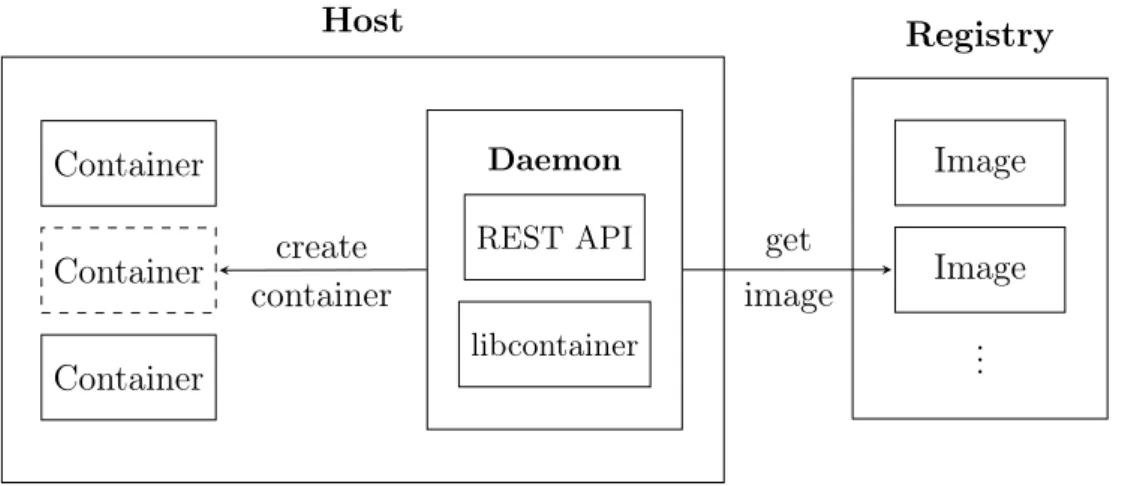
Host Container Container Container Daemon REST API libcontainer Registry Image Image .. . get image create container
Figure 2.2: An overview of the Docker architecture. The Docker Daemon pulls images from the registry in order to populate the empty container created by libcontainer.
2.2.1
Docker Architecture
The main entity of Docker is the Docker Engine which runs on top of the OS and consists of, among others, the Docker Daemon. The daemon uses libcontainer to create the container environment [19]. The purpose of the Docker Daemon is to manage containers, images, networking and volumes and to listen for requests to its REST API. The daemon creates a container and populates it with the application and necessary runtimes using Docker Images. The image acts as a read-only instruction to the daemon on how the container should be built. As an example, there are specific images for running .NET applications or Apache servers [3, 59]. Images can also be based on other images to, for example, create an image with both the application code and necessary runtimes. Finally, the images are stored in a Docker Registry which the daemon uses to pull the Docker images from. An illustration of the components mentioned in this section is provided by figure 2.2.
2.2.2
Container Networking Interface
The Container Networking Interface (CNI) is a CNCF project which aims to provide a specification for container networking in order to make them less dependent on the hosting environment [17]. As containers, such as Docker containers [98], can be config-ured to utilize a CNI-based network, any solution which support the interface is able to communicate with the container and the containerized application.
2.2.3
Isolation Mechanisms
In Docker the isolated container environments are implemented through utilizing Linux kernel features, specifically namespaces, control groups, capabilities [20]. In addi-tion, Linux Security Modules (LSMs) such as AppArmor and Security-Enhanced Linux (SELinux) may be used to harden the isolation. Finally, the Linux kernel Secure Com-puting mode (Seccomp) may be used to limit system calls. A short summary of these
CHAPTER 2. THEORY
isolation mechanisms is provided below with regard to Docker.
• Namespaces: When Docker runs a container, it creates several isolated workspaces through namespaces. On Linux it creates namespaces for process isolation, network-ing and file system mountnetwork-ings. The process isolation prevents a process inside a container from seeing processes, files, etc. outside the container.
• Control groups: Docker uses control groups to limit the resources each container uses to ensure that a set of co-located containers are able to function on a system. • Capabilities: Linux kernel capabilities allow the superuser privilege to be split into a set of distinct privileges. This allows the container processes to run using capabilities instead of being run as superuser.
• AppArmor and SELinux: The LSMs AppArmor and SELinux provides separa-tion between applicasepara-tions, in this case the containers, through a Mandatory Access Control scheme. With regard to security the LSMs offer methods of hardening docker hosts to a more satisfactory degree. The available LSMs depend on the Linux distribution. AppArmor for example, is available in Ubuntu and openSUSE by default [4] while SELinux is available in Red Hat Enterprise Linux and Fedora [83]. In general, SELinux is considered complex by offering fine-grain control aimed at security experts while AppArmor offers simpler methods of configuration [82]. • Secure Computing mode: Seccomp allows limitation of the available commands
that are exposed to containerized applications [21]. This is achieved by making a process enter the mode where the available system are limited. [58].
2.2.4
Container Sandboxing
Sandboxes may be utilized in order to increase the isolation of containers in addition to the mentioned security mechanisms. One example of achieving such sandboxing is to introduce another kernel beneath the container-layer. This can be done through two main methods [55].
• VM-based Sandboxing: Virtualization is one method which may be utilized to sandbox containers. If a container is placed on top of an OS running in a VM the environment will provide separation to containers located in different VMs.
• Container Kernel Sandboxing: By providing each container with its own kernel, the separation between containers can be increased as the surface of a container kernel is smaller than the surface of an OS kernel.
As VM-based sandboxing requires an OS it increases the overhead which may reduce the benefits of introducing containers. In order reduce the overhead, the VM may run a specialized OS which only contain the essential functionality to run containers. One example of this is the open-source project Kata Containers which run containers in lightweight VMs with a Linux-based OS such as Fedora [38, 39]. Kata Containers support the OCI specification allowing it to run Docker containers. Providing containers with separate kernels instead of a VM and OS reduces the footprint further. One solution
which uses this approach is the newly open-sourced container runtime sandbox gVisor from Google [31]. Its kernel implements parts of Linux kernel and provides support for the OCI specification.
2.2.5
Container Escape
Container Escape is an attack which escapes the isolated container environment onto the underlying OS. Since the security of Docker containers are dependent on the kernel, any vulnerability in the kernel translates to a security risk for the host as a whole, and with it, all containers running on that system. While not all vulnerabilities are of such severity it is notable that the Linux kernel was found to have 453 vulnerabilities in the year 2017 [62] of which 288 was classified as high severity vulnerabilities [63]. One such high severity vulnerability discovered in 2016 was CVE-2016-5195, a privilege escalation vulnerability nicknamed Dirty COW [61], which could be used to successfully perform a container escape [22]. After a patch was released another vulnerability, CVE-2017-1000405, was found in the patch [76]. While not as severe it also allowed a malicious user to run local code if exploited. While container sandboxing could mitigate kernel-based escape attacks, there are other means to achieve a container escape.
Besides kernel exploits, a container escape could be achieved through attacks on other surfaces [1]. One such example is through the storage mounting in Kubernetes, covered in section 2.3, where the vulnerability CVE-2017-1002101 could be exploited as an escape attack [77]. Since the vulnerability is in the orchestration and not containerization, the container sandboxes do not mitigate such attacks.
2.3
Container Orchestration
Kubernetes is a container orchestration solution for deploying, scaling and managing con-tainers across multiple physical or virtual machines [15]. It was open-sourced by Google and is built on their experience of building container management solutions [6]. This section focuses on its architecture and cluster networking as well as container placement logic.
2.3.1
Kubernetes Architecture
Kubernetes uses a master-slave architecture where the master and slaves are hosts in a network [46]. Since Kubernetes does not differentiate between hosts, any host such as a VM run by a cloud provider or a bare-metal server can be utilized simultaneously in Kubernetes. Terminologically the slave hosts are called nodes and are intended for running the containers assigned by the master [43]. Together, a set of nodes with a corresponding master forms a cluster which in turn can be configured by the Kubernetes API exposed by the master. The API offers methods to deploy containers as well as providing a main interface for administering the cluster.
Kubernetes adds an abstraction layer on top of containers - pods. A pod is a set of containers which share storage and networking resources as well as specification for building and running the containers [50]. Containers running within the same pod share the same context which with regard to Docker is the shared namespaces and control
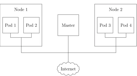
CHAPTER 2. THEORY Master Internet Node 1 Pod 1 Pod 2 Node 2 Pod 3 Pod 4
Figure 2.3: A simplified overview of a Kubernetes cluster. All pods and nodes may communicate freely by default.
Master apiserver scheduler etcd Node kube-proxy
kubelet Cont. Runtime
Pods Pod Pod Pod new pod request create pod
Figure 2.4: An overview of the Kubernetes Architecture. The apiserver receives a request to create a new pod and notifies the scheduler which selects a node and creates the pod.
groups among others [50]. Kubernetes uses pods for both internal components as well as the smallest unit of deployment when deploying containers. Both the master and the nodes run pods but only the nodes run the pods with the containerized applications. A simple overview of a Kubernetes cluster is provided by figure 2.3.
The life cycle of pods is volatile. They may terminate or relocate to another node and are not guaranteed access to the same resources unless explicitly specified [49]. The life cycle of each pod is defined through phases which are provided through the PodStatus and ContainerStatus objects [48]. These can be used together with hooks to create an event when a pod starts or terminates [44]. In addition, pod can be replicated across nodes to offer high availability.
Since the master and the nodes have distinct roles their architecture differs and contain different sets of components. Below is a summary of the components relevant for the scope of this thesis. An overview of these are shown in figure 2.4.
Components in Master
The master has several components which constitutes the logic of the cluster. The com-ponents of particular interest are the Kubernetes apiserver, the etcd storage system and the Kubernetes scheduler.
• etcd: In order for the master to keep track of the state of the cluster it uses the distributed key-value storage system etcd [46]. The distributed form is essential to protect the cluster state and ensure availability.
• apiserver: The Kubernetes apiserver is the main interface for interacting with the cluster [46]. It is a REST API which accepts requests through HTTP. Each request is passed through authentication, authorization and admission controllers in order to verify the legitimacy of the request and requester. These are covered in section 2.3.4.
• scheduler: The scheduler is the component which deploys or schedules pods onto nodes [46]. It listens for new pods and selects a node to execute on. The scheduling process can be customized in various manners which are covered in section 2.3.3.
Components in Nodes
The components of the nodes regard handling new pods, ensuring that they start and en-suring communication to other pods. While the specific components may differ depending on cluster setup the list below are the core components provided by Kubernetes.
• kubelet: The Kubelet is an agent which, through the defined pod specifications, ensures that the containers are running inside the pods [46].
• kube-proxy: The kube-proxy component configures a proxy such that the pods may communicate with each other through proxy-endpoints [46]. While there are several proxy implementations the default mode configures the proxy with iptables which contains IP mappings between the static proxy IP and the pod-IPs [52].
CHAPTER 2. THEORY
• Container Runtime: The containers are run using a container runtime. While there are several runtimes supported by Kubernetes this thesis focuses on Docker containers.
2.3.2
Kubernetes Networking
Kubernetes does not implement the cluster networking [42]. Instead it supports the CNI specification, covered in section 2.2.2, and assumes a network model which the network implementations must satisfy. This section covers this model as well as other network constructs.
Network model
Kubernetes assumes a network model where any two pods in a cluster can communi-cate with another [42]. With respect to the scope of this thesis there are two specific requirements provided by Kubernetes cluster network model that are of interest.
1. all containers can communicate with all other containers without NAT. 2. all nodes can communicate with all containers (and vice-versa) without NAT. The model implies that all container and node must be able to communicate with each through IP without needing to perform any IP translation beforehand.
Network Polices
In order to control how the pods may communicate many third-party networking solutions uses network policies which uses Kubernetes Labels to identify pods [10, 71]. Labels are used instead of IP addresses due to ability the pods have to relocate. The network policies can be scoped to, for example, ensure all pods block incoming traffic on a specific port. While providers may implement their own network policies, Kubernetes provides a specification for a NetworkPolicy object [47]. Since it is not part of the CNI the support is dependent on the chosen networking solution.
2.3.3
Pod Scheduling Control
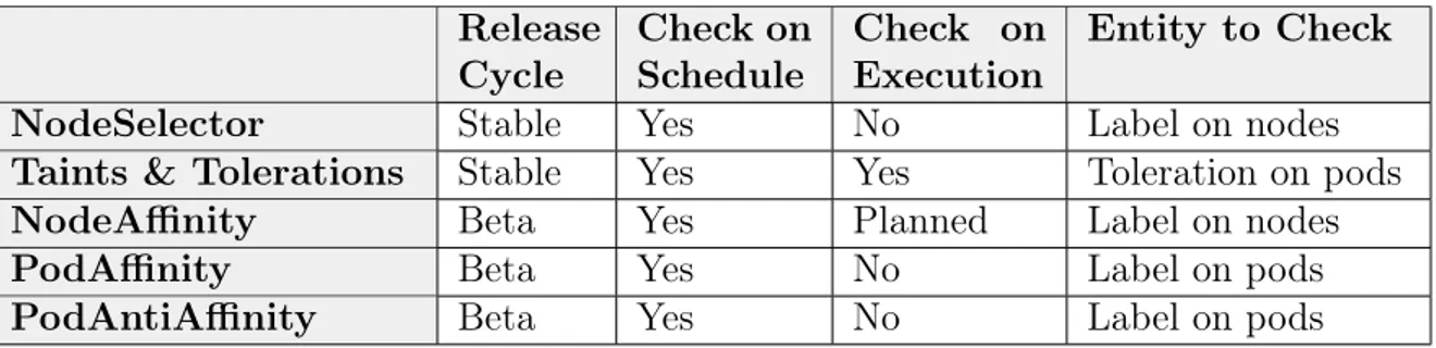
There are five methods for controlling the pod scheduling process, NodeSelector, Taints and Tolerations and three Affinity types. A comparison of them are given by table 2.1.
NodeSelector
The NodeSelector enables a pod to only be scheduled on to nodes which contain a specific label [41]. After the scheduling is completed and the pod has entered the execution phase the selection logic is no longer verified. If the label is removed from the node the pod will remain scheduled on the node.
Table 2.1: A comparison of pod scheduling control mechanisms. The check in the scheduling process verifies the specified logic before scheduling only while the check in the execution process verifies the logic as long as the pod is scheduled. while Only taints and tolerations and NodeAffinity will have support to enforce the pod co-location both during schedule and execution.
Release Cycle Check on Schedule Check on Execution Entity to Check NodeSelector Stable Yes No Label on nodes Taints & Tolerations Stable Yes Yes Toleration on pods NodeAffinity Beta Yes Planned Label on nodes PodAffinity Beta Yes No Label on pods PodAntiAffinity Beta Yes No Label on pods
Taints and Tolerations
Taints allows nodes to reject pods which do not have a toleration for the taint [53]. The tolerations are specified in the pod specification and if no sufficient toleration is defined the node may respond various effects. There are three supported effects, PreferNoSchedule, NoSchedule and NoExecute.
Affinity (beta )
There are three affinity types, NodeAffinity, PodAffinity and PodAntiAffinity which offer more versatile label selector logic [41]. All three types offer support for two enforcement modes with different priorities. For the scope of this thesis only one such mode is of interest, the requiredDuringSchedulingIgnoredDuringExecution (RSIE). Note that similar to NodeSelector, the RSIE mode do not verify the selector conditions during the execution phase, after the scheduling process is complete. Below is a summary of the affinity types. Note that the affinity types are in beta for the viewed Kubernetes version, v1.10, and may therefore change once it reaches stable in the release cycle.
• PodAffinity: Restricts the scheduling by requiring that the pod can only be sched-uled to a node if other pods on that node carry the specified labels which satisfy the selector logic. This enables strategies for co-locating pods such that a pod is only deployed to nodes where another set of pods exist.
• PodAntiAffinity: Acting as the opposite of PodAffinity, PodAntiAffinity restricts scheduling to nodes where certain pods do not exist. This enables strategies to prevent co-location of pods on to the same node.
• NodeAffinity: NodeAffinity with the RSIE mode is similar to NodeSelector in that it restricts scheduling to nodes by the labels the node carries while utilizing the affinity selector logic. Additionally, NodeAffinity has an additional enforcement affinity mode which verifies the selector logic in the execution phase as well, the requiredDuringSchedulingRequiredDuringExecution (RSRE) mode. RSRE has however not been implemented yet.
CHAPTER 2. THEORY
2.3.4
Kubernetes API Security
Access to the Kubernetes API is restricted in three steps Authentication, Authorization and Admission Control which are executed in the stated order [45].
1. Authentication verifies, after the TLS handshake, that the request originates for a legitimate user. This is achieved by certificates, tokens or proxies.
2. Authorization ensures that a given user is permitted to perform the requested action. Kubernetes supports multiple authorization modules such as Role-Based Access Control.
3. Admission Control is composed by a set of modules which are executed in order to transform or reject requests that have passed the authorization step. As an example, the NodeRestriction controller enables limiting the access of kubelets such that each kubelet can only modify the Pod and Node API objects related to the kubelet.
2.3.5
Cluster Intrusion Detection
If an attacker successfully achieves a remote code execution within a pod or on the node the cluster becomes susceptible to attacks. Such attacks would propagate over the cluster network and making both nodes and pods potential targets. In order to detect network attacks in general, Intrusion Detection Systems (IDS) may be utilized. One solution is Snort which combines signature-based and anomaly-based mechanisms [24, 80]. While Snort is widely popular [85] it is not compatible with container orchestrated environments due to the dynamic nature of the cluster. Instead, solutions from vendors such as Sysdig and Twistlock are available which provide IDS capabilities as part of their software suites for cloud-native environments [87, 88]. In addition, there are distributed tracing systems which provide traffic observability in clusters. Many such solutions are inspired by Dapper [36, 100], a distributed system tracing infrastructure created by Google, which focuses on providing better understanding of the system behavior to find, for instance, performance issues [29]. However, as such solutions are oriented toward optimization and monitoring of micro-services they do not provide IDS capabilities.
2.4
Cluster Networking Solutions
While Kubernetes does not implement the cluster networking it supports the CNI spec-ification, through which there are several third-party solutions available such as Flannel by CoreOS and Project Calico by Tigera [42]. The available cluster networking solu-tions can be categorized based on their network topologies. This section covers network implementation using Flat Network Topology and Overlaying Network Topology.
2.4.1
Flat Network Topology
As each pod receives its own IP the flat network topology solutions utilize the pod IP addresses for routing of pod-to-pod packets. Due to this the topology requires some
routing mechanism for packets to reach the node where a designated pod is located. Many flat topology networking solutions utilize the Border Gateway Protocol (BGP) for network discovery and to verify that endpoints are online [16, 74]. BGP creates TCP sessions to peers and repeatedly sends keep-alive messages to maintain the session.
Project Calico achieves the flat network topology by using Linux kernel features, the routing tables and iptables, as well as BGP. The routing tables are responsible for packet forwarding and iptables for packet filtering [73]. In order to maintain the routing tables updated Calico utilize an agent and a BGP client [70]. The agent runs on each node and creates direct routes to pods located on that node through interfaces. When the direct routes have been setup the BGP client reflects the direct routes as indirect routes on other nodes such that the node becomes a gateway for the pods it holds. Project Calico supports Kubernetes NetworkPolicy objects [72].
2.4.2
Overlay Networking and VXLAN
Overlay networking defines network on top of another through VLANs, tunnels or other techniques. Packet encapsulation is one method which sends packets through tunnels where all tunnels between the hosts represent the overlay network. A packet is encap-sulated by being placed inside another packet which in turn is sent to destination where the packet is decapsulated by removal of the outer packet allowing the inner packet to be routed further. There are several packet encapsulation techniques. The focus of this section is Virtual Extensible LAN (VXLAN).
The VXLAN tunnels starts and ends with VXLAN Tunnel Endpoints (VTEPs) which encapsulate packets going into the tunnel and decapsulates packets received from the tunnel [11]. Each packet is encapsulated in a UDP packet which is used to tunnel the encapsulated packet to the destination VTEP, from where the packet is decapsulated and routed further. Each VTEP consist of network interfaces of two kinds, one interface which communicates with other VTEPs and another set of interfaces which represent the routing destinations.
With regard to Kubernetes, each node has a VTEP and each packet which is sent from a pod is tunneled through the VTEP. When such packet leaves the node its source and destination IP addresses are node-IPs while the source and destination of the encapsulated packet are pod-IPs. Below are two solutions which implement cluster networking using VXLAN.
OpenShift SDN
OpenShift Origin is a PaaS and open-source community project which uses Kubernetes for container orchestration. OpenShift Origin is used as the upstream project for the com-mercial OpenShift platform offered by Red Hat [78]. As Kubernetes does not implement any networking OpenShift provides OpenShift SDN for cluster networking. OpenShift SDN is based on Open vSwitch and uses VXLAN for packet encapsulation. It supports several SDN plugins, one of which supports Kubernetes NetworkPolicy objects [75].
CHAPTER 2. THEORY
Flannel
Flannel is an open-source networking solution by CoreOS which focuses on providing an IP network layer between nodes [26]. It satisfies the Kubernetes networking model through several backend methods of which VXLAN is the recommended choice [25]. Flannel does not offer support for Kubernetes NetworkPolicy objects but can be used together with Project Calico through the Canal solution to utilize the NetworkPolicy support provided by Calico [7].
Result
This chapter present the findings and proposals of this thesis. Section 3.1 to 3.4 cover the chosen models and the baseline architecture which the proposals are compared against as well as the risk mindset of container escapes. The proposals are then provided by section 3.5 and 3.6. The former describes methods on how container escape risks could be mitigated and the latter present cluster architectures. With regard to DSRM, Section 3.1 represent the objectives which a valid solution must satisfy. The other sections cover the design and demonstration.
3.1
Solution Objectives Model
Given a set of applications hosted on a cloud, an objectives model is defined as required by DSRM, the chosen research methodology. The motivation of the model regards the risks of co-located containers as well as the risks of unfiltered traffic. The goal of the model is therefore to both hinder and detect an attacker. The model is defined as follows.
1. Closure: All applications in the system must be separated according to the Prin-ciple of Least Privilege such that an application cannot reach another through the shared hardware, OS or network given that no such access is required.
2. Traceability: The system must allow network monitoring of communications such that an IDS may be utilized to detect network propagated attacks.
3.2
Application Classification System
In order to utilize computational resources while providing sufficient separation the fol-lowing class-based separation system was chosen to differentiate the requirements which each application has on isolation.
• Class O: The application is open for any co-location and requires no separation. • Class PG: The application together with a set of other applications forms a
private group which together require separation from applications not in the group. • Class P: The application requires a private and dedicated separation.
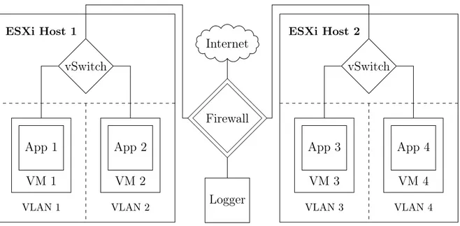
CHAPTER 3. RESULT Firewall Internet Logger ESXi Host 1 VLAN 1 VLAN 2 VM 1 App 1 vSwitch VM 2 App 2 ESXi Host 2 VLAN 3 VLAN 4 VM 3 App 3 vSwitch VM 4 App 4
Figure 3.1: An overview of a cloud architecture using virtualization with a 1:1 mapping between VM and application. The VLANs ensure all traffic between VMs inside the ESXi hosts are routed through the firewall where packet filtering is enforced. This architecture serves as a baseline for container orchestrated clouds.
Each application must have a distinct class. As an example, the Class PG may be suitable for applications tightly coupled together or applications which utilize a micro-service architecture. The process of classifying an application regards information security and is outside the scope of this thesis.
3.3
Baseline Architecture
As defense departments and the defense industry in general operate with among the highest demand on security it can be derived, from the FOI report mentioned in sec-tion 2.1, that applicasec-tions hosted through virtualizasec-tion could offer a baseline to which container orchestrated clouds can be compared against with regard to the separation of applications.
In order to achieve separation between applications, an architecture is proposed. The architecture warps each application in a VM to create a 1:1 relationship between VM and application. The VMs in turn are driven by the bare-metal hypervisor ESXi due to its low-level implementation and its track-record of having few known vulnerabilities. Through the relationship, all applications are isolated and treated as Class P applications regardless of their actual classification. To control the VM-to-VM communication within an ESXi host each VM has a dedicated VLAN [96] which will route the traffic out of host such that a firewall may filter it. The static IP address of the VM is used as an identifier for the application. The IP of a received packet is used in the firewall to filter the VM-to-VM communication, and with it, communication between applications.
This architecture, seen in figure 3.1, satisfies the objectives model and may provide an acceptable risk even for the most security demanding environments. In this thesis, the
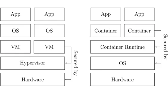
Hardware Hypervisor VM VM OS OS App App Virtualization Hardware OS Container Runtime Container Container App App Containerization Secured b y Secured b y
Figure 3.2: A comparison of virtualization and containerization layers and se-curity enforcement. Virtualization is secured by the hypervisor and hardware while containerization is secured by the container runtime and the OS kernel.
architecture is used as a baseline object of comparison to container orchestrated clouds with regard to application separation.
3.4
Mitigating Container Escape Risks
Escape attacks pose a risk for both virtualization and containerization, as seen in sec-tion 2.1.4 and 2.2.5. While both technologies increase the attack surface, the increase varies greatly between virtualization and containerization. In virtualization, separation between VMs on shared hardware is achieved through the hypervisor and hardware-level virtualization mechanisms. Containers on the other hand depend on the Linux kernel for security and require configuration to harden the container isolation through SELinux, Seccomp, etc. As a result, containerization through Docker on Linux implies a wider attack surface than virtualization through ESXi. The attack surface creates risks both with regard to the technical implementations and to operations. The only case found in the literature study of this thesis where a VM escape was achieved in ESXi, not taking hardware-level attacks into account, were through the CVEs recently discovered in con-nection with Pwn2Own, described in section 2.1.4. In this manner VM escapes pose a more acceptable risk, despite taking the new CVEs into account. Container escapes on the other hand, may not be an acceptable risk due to the difference in attack vectors.
The security mechanisms which Docker containers rely on are reliant on the OS kernel while the baseline architecture implements hardware-level separation, as seen in figure 3.2. With regard to the discoveries of Linux kernel CVEs such as Dirty COW, described in section 2.2.5, the security mechanisms, including the LSMs, could be rendered ineffective if such vulnerability was to be exploited. In addition, vulnerabilities in the container orchestration may also be utilized to achieve similar results. While most vulnerabilities
CHAPTER 3. RESULT
may not be of such severity, the Swedish Police Authority and other security demanding environments may not be willing to accept such risk. In order to provide separation between containers a sandbox mechanism must be used. To provide an acceptable risk for the Authority, the sandbox of the container must at the present day be VM-based. The hypervisor of the VM-sandbox must also be bare-metal to limit the attack surface.
In order to reduce the overhead associated with VM-based sandboxes and provide sufficient separation between applications, a container co-location management scheme is proposed. Each VM in the scheme is used as a sandbox for a set of containers which co-location is based on their application classification. As there is no mechanism to control the communications of containers within the same pod, there must be a 1:1 mapping between pod and container. In this manner an intruder which achieves a container escape will be limited to a controlled set of applications which, against each other, do not require separation.
3.5
Pod Co-location Strategies
There are 3 main categories of mechanisms which may alter the scheduling process, as described in section 2.3.3.
• NodeSelector and NodeAffinity limit which nodes a pod can be scheduled to. • Taints and Tolerations limit which pods a node will schedule or run.
• PodAffinity and PodAntiAffinity limit which pods can be scheduled together. As noted several solutions may be crafted from the mechanisms above. In order to ensure that some containers do not co-locate, a scheme is proposed using the Kubernetes scheduling controls which presents a formalized method to introduce separation of the pods on different hosts. In addition, other potential schemes are discussed.
3.5.1
The Pod Co-location Scheme
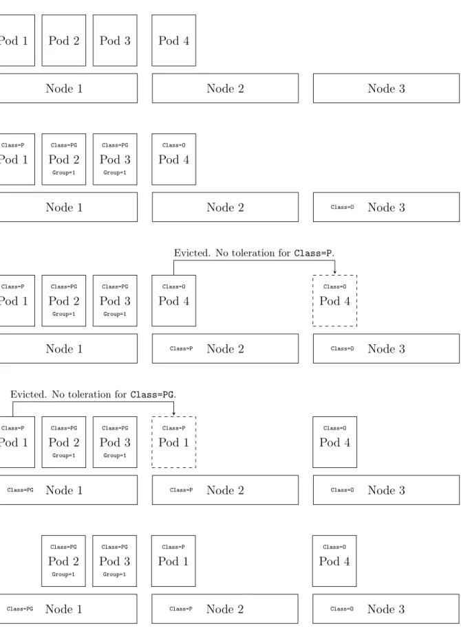
The scheme implements separation by allocating nodes to application classifications and by preventing some pods from being scheduled together. It has reusable logic and relies on Taints, Tolerations, PodAntiAffinity and pod labels. Taints provide the scheme with separation of the classes while PodAntiAffinity further separates pods within the P and PG classes. In addition, the scheme makes P class applications and each group of PG class applications require distinct nodes. An example, the impact of the scheme on the co-location is provided by figure 3.3.
Class-based Node Allocation
Each and every node must be allocated to an application classification such that it will only accept and run applications from its allocated classification. This is done by creating a taint on each node with a NoExecute effect where the taint reflects the classification name. For simplicity the taints can have the key-value Class=O, Class=PG and Class=P. All pods which contain applications of a given class must have the toleration for the corresponding key-value taint of the class.
Node 1 Node 2 Node 3 Pod 1 Pod 2 Pod 3 Pod 4
Node 1 Node 2 Class=O Node 3 Pod 1 Class=P Pod 2 Class=PG Group=1 Pod 3 Class=PG Group=1 Pod 4 Class=O
Node 1 Class=P Node 2 Class=O Node 3
Pod 1 Class=P Pod 2 Class=PG Group=1 Pod 3 Class=PG Group=1 Pod 4 Class=O Pod 4 Class=O
Evicted. No toleration for Class=P.
Node 1
Class=PG Class=P Node 2 Class=O Node 3
Pod 1 Class=P Pod 2 Class=PG Group=1 Pod 3 Class=PG Group=1 Pod 1 Class=P Pod 4 Class=O
Evicted. No toleration for Class=PG.
Node 1
Class=PG Class=P Node 2 Class=O Node 3
Pod 2 Class=PG Group=1 Pod 3 Class=PG Group=1 Pod 1 Class=P Pod 4 Class=O
Figure 3.3: An overview of the separation flow of pods where Pod 2 and Pod 3 form a private group, Pod 1 require dedicated separation and Pod 4 do not require any separa-tion.
CHAPTER 3. RESULT
To protect against abuse, any pod which contains toleration for the key Class without a defined value must be rejected by a Kubernetes admission controller. This also applies to pods with toleration for multiple classes. Through this, the scheme ensures that each node cannot run pods outside of its class allocation.
Additional Requirement for Class P
Each pod which contain an application of Class P must define a PodAntiAffinity RSIE selection logic such that the pod is only scheduled on to empty nodes. This is achieved through use of the DoesNotExist operator together with a special key which no pod has. As no pod has the key, the selection logic applies to all pods in the cluster. Therefore, the pod will only be scheduled on to nodes where no pod exists. To ensure the special key is in fact unused an admission controller is utilized to remove such key from the metadata of the pod specifications.
Additional Requirement for Class PG
Each pod which contain an application of Class PG must define a PodAntiAffinity RSIE selection logic such that the pod is only scheduled on to nodes which are either empty or contain pods from the same private group. This is achieved by assigning each private group with a distinct key-value label which all pods of that a group bear. This can be seen in in figure 3.3 where the group label Group=1 is used. The labels are then utilized with PodAntiAffinity RSIE together with the DoesNotExist operator. This will select all pods in the cluster that are not in the same private group as pods which cannot be scheduled with.
3.5.2
Other Potential Schemes
Another potential scheme in controlling the separation is through NodeAffinity RSRE together with key-value labels attached on to nodes. Such scheme could be implemented to create groups of nodes where all Class O applications would have a large set of nodes and Class P and PG applications would have many small set of nodes. In addition, every Class P application would have its own set of nodes and the PG applications would be placed on a set of nodes which reflect their private group.
While the RSRE mode has not yet been implemented in NodeAffinity it is a require-ment for graduating Affinity to v1, the first stable release stage [79]. Using the RSIE mode instead comes with consequences as pods will not be rejected if the selection logic fails in the execution phase. This may happen when a node label is removed. Until then, the RSIE mode must be used together with the drain and uncordon commands [51] to force pods to be re-scheduled.
3.6
Network Segmentation Designs
In this section three design proposals are presented which achieve network segmentation with regard to Kubernetes clusters. The design proposals are the Policy-driven Micro-Segmentation, the Centralized Firewall Micro-Segmentation, and the Inter-Cluster Firewall
Seg-Master Cluster History Catalog check for
new state
push new state to subscribers
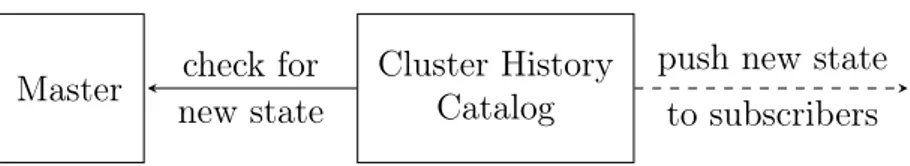
Figure 3.4: An overview of the Cluster History Catalog. It synchronizes with the Kubernetes Master through heartbeat requests in order to push new states to dependent systems and provide translation between pod IP and application.
mentation. In addition to the architectures the Cluster History Catalog is introduced as well as the Segmentation Composer.
3.6.1
The Cluster History Catalog
The IDS solutions mentioned in 2.3.5 which are compatible with the dynamic nature of cluster networks are not dedicated on network intrusions. In comparison with Snort they differ greatly in detection mechanisms [24, 88]. While the specific detection mechanisms of the IDS are not in scope of this thesis, the compatibility and detection locations are. In order to satisfy the objectives model, a combination of host and container-level traceability required which the cluster-compatible solutions do not provide to the same extent. Therefore, in order to utilize IDS solutions such as Snort and allow traceability for both nodes and pods, a new cluster component is proposed.
Logging of pod-to-pod communications based on pod-IPs as packet source and desti-nation introduce the issue of cluster state changes. Any translation between pod-IP and application may become invalid if the cluster state has changed. If a pod is relocated its pod-IP in the current state may not refer to the same application as in the previous state. Any log entry made in the previous state cannot be used to understand the traffic as its corresponding state no longer exists. To tackle this issue the Cluster History Catalog is proposed which contain the following two main functionalities and an additional third functionality for extensibility.
1. State-mapping: Given a point in time the system can retrieve the state of the cluster during that time.
2. Pod-mapping: Given a pod-IP and a cluster state the system can retrieve the pod corresponding to the pod-IP of that state together with information related to the pod.
3. State-subscription: Following the publish-subscribe architectural pattern the sys-tem allows other syssys-tems to subscribe to state changes which are pushed, or pub-lished, by the Cluster History Catalog.
The Cluster History Catalog, as seen in figure 3.4, implements the functionalities by communicating with the Kubernetes master where the current cluster state is stored. In order to detect changes in the cluster state the Cluster History Catalog stores a complete history of the previous cluster states up until the current state. As the Kubernetes master contains a REST API the Catalog performs repeated HTTP requests at a sufficient time
CHAPTER 3. RESULT
Node
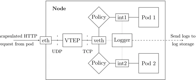
eth VTEP veth Policy Policy int1 int2 Logger Pod 1 Pod 2 UDP TCP Encapsulated HTTP request from pod
Send logs to log storage
Figure 3.5: An overview of the packet flow in VXLAN-based clusters. The received UDP packet is an encapsulated HTTP packet which is decapsulated in the VTEP and routed to the correct pod.
interval to achieve a heartbeat synchronization. The synchronization with the master is used instead of the hooks mentioned in section 2.3.1 since the hooks run inside the containers which may be controlled by an attacker. The length of the time interval of the synchronization must be taken into account to prevent delayed changes in the Catalog. While container startup time is fast, it is not instantaneous. This creates a time window between a container being started and a running container. In addition, the pod phase is available through the REST API of the master, which provides labels on if the containers in pod are starting, running or being terminated. If the heartbeat time interval is short enough to detect containers which are being terminated or starting, then the time delay will be a negligible factor with regard to the dependent systems. Any state change in the cluster will thus trigger an event in the Cluster History Catalog such that the change is reflected in the history and propagated on to subscribing systems.
3.6.2
The Policy-driven Micro-Segmentation
A minimal cluster setup, as seen in figure 2.3, allow all pods and all nodes to communi-cate unhindered. The task of introducing separation in such network between pods can be achieved by utilizing network policies. However, as the Kubernetes Network Policy object is implemented by the chosen cluster network solution and the network segmen-tation is fundamental to network security it is important that the chosen networking solution provides support for policies and the ability to log before and after the policies are enforced.
The transition from segmentation through firewalls, as used in traditional cloud com-puting, to segmentation, or micro-segmentation, based on policies marks a shift on net-work separation from hardware to software. Since the micro-segmentation through Net-work Policy objects already are integrated with Kubernetes and enforced on the respective nodes the policies are dynamically managed. A policy can be configured to deny all traf-fic between pods except the traftraf-fic required for the function of the pod, satisfying the Principle of Least Privilege. The cluster network solutions Calico and OpenShift SDN
both provide Network Policy support and provide methods for logging through network interfaces as seen in figure 3.5. In order to interpret log entries, the logging could be performed in coordination with the Cluster History Catalog as previously explained. Fi-nally, the network traffic logs are extracted from the interfaces on each node using a packet sniffer such as Wireshark and sent to an external logging system outside the node for storage.
By utilizing the Network Policy objects, pod-to-pod communications may be regu-lated. However, in order to prevent a node from reaching any given source on the internet external packet filtering is still required to achieve separation between the cluster and the internet. To solve this, a firewall is added to introduce such functionality. Additionally, node-level firewalls must also be used in order to filter node-level packets not originated from or destined to pods. In this regard, policies are the entity which filters pod pack-ets inside the cluster while the node-firewalls filters non-pod packpack-ets inside the cluster. Finally, the external firewall filters the traffic between the cluster and the rest of the internet. The illustration of this can be seen in figure 3.6 where a VXLAN networking solution with policy support is used.
CHAPTER 3. RESULT
Firewall
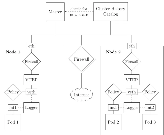
Master Cluster History Catalog Internet Node 1 eth Pod 1 int1 Policy veth VTEP Firewall Logger Node 2 eth Pod 2 Pod 3 int1 int2 veth VTEP Firewall Logger Policy Policy check for new state
Figure 3.6: An overview of the Micro-Segmentation Proposal with a VXLAN-based network. The Cluster History Catalog enables traceability for pod com-munications and the Kubernetes Network Policies provide network separation between pods. In addition, the node-firewalls provide separation between nodes while the external firewall provide separation against the internet and prevents pods and nodes from accessing unwanted outbound resources.
Master Cluster History Catalog Segmentation Composer Firewall check for new state push new state configure on new state
Figure 3.7: An overview of the Segmentation Composer and its integration with firewalls and the Cluster History Catalog. The Composer receives a new state from the Catalog which it uses to configure the firewall segmentation of pod networking.
3.6.3
The Segmentation Composer
Traditional network segmentation achieved with firewalls, through packet filtering of IPs, is suitable where each host has a static IP. Since however, pod-IPs in Kubernetes are dynamically allocated, the described segmentation architecture requires modification in order to operate. In order to solve this issue, the Segmentation Composer is proposed. The Composer, as seen in figure 3.7, is responsible for configuring intermediary firewalls based on the pod locations in the latest cluster state. By subscribing to state changes from the Cluster History Catalog it receives the latest state and compares it to the previous state to update the firewall filtering rules accordingly.
The purpose of the Segmentation Composer is to enable dynamic updates of firewall rules to reflect the dynamic pod topology. Due to the frequency of updates the firewall needs to provide means of supporting the flow of re-configurations. Some vendors provide REST API interfaces on the firewalls that could be used for this type of re-configuration [9]. With such API the firewall configuration could be kept up-to-date and together with Segmentation Composer enable network segmentation through firewalls and provide compatibility with the traditional cloud segmentation architectures.