i
Design of an Improved Rapid
Infuser for Safe and Reliable
Fluid Resuscitation during
Surgical Care
A J D A A H M A D I
Master of Science Thesis in Medical Engineering Stockholm 2014
iii
This master thesis project was performed in collaboration with SLL Innovation Supervisor at SLL Innovation: Karin Bäckström
Design of an Improved Rapid Infuser for Safe
and Reliable Fluid Resuscitation during Surgical
Care
Design av en förbättrad övertryckskammare för
en säker och reliabel vätsketillförsel under
kirurgisk Vård
A J D A A H M A D I
Master of Science Thesis in Medical Engineering Advanced level (second cycle), 30 credits Supervisor at KTH: Matilda Larsson Examiner: Mats Nilsson School of Technology and Health TRITA-STH. EX 2014:85
Royal Institute of Technology KTH STH SE-141 86 Flemingsberg, Sweden http://www.kth.se/
v
A
BSTRACT
Rapid infusers are used for rapid fluid administration as a part of medical treatment during surgical procedures. The rapid infusers on the market today have proved to present various functional, usability and safety issues for the customers and the problems have not been adequately addressed. This has motivated SLL Innovation to develop a new improved rapid infusion system. The primary reason for considering the development of a rapid infuser device was to meet customer demands and improve safety during the acute situations when the system is to be used. The Quality Function Deployment method was used to describe the design problem systematically and facilitate the development of an improved design. To investigate the users’ issues with existing rapid infusion devices, qualitative semi-structured interviews were conducted individually with hospital staff that had experience with the rapid infuser. Customer requirements were subsequently identified to form a basis for the development process.
The results of the study indicated an evident demand for a new product. A three-dimensional (3D) computer aided design (CAD) solution was presented with enhanced properties and features that met the specifications identified. All the customer requirements were addressed in the final result. Safety was the highest rated engineering specification, thus a lot of time and effort was dedicated to solutions that could affect the safety of the system positively.
Although the final design is expected to be more efficient and safer than the competition, further research and work is needed before this can be ensured.
Keywords: fluid resuscitation, massive blood loss, pressure infuser, rapid infuser, Quality Function Deployment, QFD
vii
S
AMMANFATTNING
Övertryckskammare används för snabb administration av vätska som en del av den medicinska behandlingen under kirurgiska ingrepp. De övertryckskammare som finns på marknaden idag har visat sig presentera olika funktionella, användbarhets- och säkerhetsproblem för kunderna och problemen har inte åtgärdats på lämpligt sätt. Detta har motiverat SLL Innovation att utveckla en ny förbättrad övertryckskammare. Den främsta orsaken till att utveckla en ny övertryckskammare var att möta kundernas krav och öka säkerheten vid de akuta situationer när systemet används. Quality Function Deployment metoden användes för att beskriva konstruktionsproblemet systematiskt och för att underlätta utvecklingen av en förbättrad produkt. För att undersöka användarnas problem med de befintliga systemen utfördes kvalitativa semistrukturerade intervjuer med sjukhuspersonal som hade erfarenhet av övertryckskammare. Kundernas krav kunde därefter identifierats och utgöra ett underlag för utvecklingsprocessen.
Resultaten av denna studie visade en uppenbar efterfrågan på en ny produkt. En tredimensionell CAD lösning presenterades med förbättrade egenskaper och funktioner som uppfyllde de identifierade specifikationerna. Samtliga kundkrav behandlades i den slutgiltiga konstruktionen. Säkerhet var den högst rankade ingenjörsspecifikationen och därmed ägnades en hel del tid och arbete åt lösningar som kunde påverka säkerheten i systemet positivt.
Trots att den slutliga konstruktionen förväntas vara effektivare och säkrare än konkurrenternas, behövs ytterligare forskning och arbete innan detta kan säkerställas.
ix
A
CKNOWLEDGEMENTS
I would like to thank my two supervisors, Matilda Larsson (STH KTH) and Karin Bäckström (SÖS), for your guidance and support for which I am very glad and grateful.
Furthermore I would like to express my gratitude to all those who have helped me and assisted me with resources during this project; interview participants, the MTA staff, proofreaders and discussion partners.
Finally, I would like to thank my family and friends for your invaluable and endless support and encouragement.
xi
A
BBREVIATIONS
3D CAD ER IV MDD MPA OR QFD SCC SLSO Three-dimensional Computer aided design Emergency room IntravenousMedical Device Directive Medical Products Agency Operating room
Quality funtion deployment Stockholom Country Council
xiii
T
ABLE OF CONTENTS
ABSTRACT ... V SAMMANFATTNING ... VII ACKNOWLEDGEMENTS ... IX ABBREVIATIONS ... XITABLE OF CONTENTS ... XIII
1 INTRODUCTION ... 1 1.1 SLLINNOVATION ... 1 1.2 PROBLEM DEFINITION ... 2 2 OBJECTIVES ... 3 3 DEMARCATIONS ... 4 4 BACKGROUND ... 5
4.1 HUMAN BODY FLUIDS ... 5
4.2 FLUID RESUSCITATION ... 6
4.3 RAPID INFUSERS ... 7
4.4 PRODUCT DEVELOPMENT ... 8
4.4.1 QUALITY FUNCTION DEPLOYMENT ... 8
4.4.2 IDEA GENERATION ... 11
5 METHODOLOGY ... 13
5.1QUALITY FUNCTION DEPLOYMENT ... 13
5.2 PROTOTYPING ... 16
5.2.1 IDEA GENERATION ... 16
5.2.2 COMPUTER AIDED DESIGN ... 17
6 RESULTS ... 18
6.1 QUALITY FUNCTION DEPLOYMENT ... 18
6.2 PROTOTYPING ... 25
6.2.1 COMPUTER AIDED DESIGN ... 25
6.2.2 DESIGN SPECIFICATIONS ... 26 7 DISCUSSION ... 30 7.1 RESEARCH LIMITATIONS ... 32 7.2 FUTURE WORK ... 32 8 CONCLUSION ... 34 9 REFERENCES ... 35
APPENDIX A–INTERVIEW QUESTIONS ... 37
1
1 I
NTRODUCTION
Surgical procedures can be associated with perioperative bleeding and the risk of massive hemorrhage followed by hemorrhagic shock. Hypovolemic and hemorrhagic shock is a life-threatening condition and is very often acute and critical. During these conditions the operating room (OR) is often a stressful and challenging environment for the surgeons and nurses. Efficient and reliable fluid resuscitation is a crucial and essential part of critical care and patient outcome.
Fluid resuscitation is most commonly done with conventional gravity infusion [1]. The infusion can be hasted by the use of a hand-inflated infusion cuff. During hypovolemic or hemorrhagic shock these methods are inadequate. The rapid infuser is used in combination with fluid warming systems to allow rapid infusion of resuscitation fluids at body temperature in patients. Dr. John Sassano at the Presbyterian University Hospital of Pittsburgh, Pennsylvania developed one of the first rapid infusers in 1982 consisting of a 3 liter fluid reservoir and a roller pump system [2]. Today there are several systems available on the market with different constructions and pressurized air sources. Rapid blood transfusion systems are used as a standardized procedure to achieve rapid blood replenishment during surgical procedures in the anesthesia and intensive care unit, emergency room (ER), obstetrics and gynecology and urology departments. The fluids infused are blood products, crystalloids and/or colloids.
SLL Innovation at Stockholm South General Hospital (Södersjukhuset) in Stockholm, Sweden has identified various functional, usability and safety issues with the rapid infusers available at the hospital, motivating them to develop an improved rapid infuser. Thus, this master thesis was made for SLL Innovation at Stockholm South General Hospital and was intended to further investigate the issues and present possible design solutions to the identified problems.
1.1
SLL
I
NNOVATIONSLL Innovation was established in 2003 at Danderyds University Hospital and is an innovation system within the Stockholm County Council (SCC). SCC is responsible for public transport and all publicly financed healthcare in Stockholm. SCC is one of the biggest employers in Sweden and 96 percent of their employees work in healthcare. [3]
SLL Innovation offers a concept to transform ideas from employees to new innovative products that facilitate their daily work and improves patient safety and care. They work closely together with the healthcare personnel and identify and
2
develop ideas created by the hospital staff deemed to be commercialized. SLL Innovation also offers a variety of services for Medtech companies and entrepreneurs that are engaged in medical device development and are interested in cooperating with the healthcare sector. In 2010 SLL Innovation was established as the main innovative organization within SCC and is today a leading innovation system in Sweden, collaborating with Danderyds University Hospital, Karolinska University Hospital, Stockholm South General Hospital and Healthcare Provision Stockholm County (SLSO).
1.2
P
ROBLEMD
EFINITIONSeveral studies have investigated the technical sufficiency and efficiency of rapid fluid infusers. The results indicate that the rapid infuser is a highly valuable device in the treatment of severely hypovolemic patients [4, 5]. Although this system has been the most effective way of delivering fluid in a short span of time, many of the rapid infusion systems on the market today present several usability issues and limitations. The engineers at SLL innovation’s department at Stockholm South General Hospital have recognized a number of usability issues identified by the hospital staff regarding the rapid infuser’s pressure chambers. The biomedical engineers have likewise experienced issues with maintenance and repair of these devices. The issues involve e.g. the design, functionality, interface, reliability and safety of the device. Hence, SLL innovation has recognized a number of product improvement and development possibilities to help the users and engineers in managing this product and consequently improve healthcare quality and safety. The product manufacturers have been contacted to discuss improvement opportunities, but have shown no interest in making any changes. Therefore SLL innovation has taken the initiative to develop a rapid infuser design that can improve patient safety, fit the hospital needs and eventually get a company interested in commercializing their design.
3
2 O
BJECTIVES
The general aim of this master thesis project was the development of the design of a new improved rapid infuser device with suggested features and modifications that facilitated the work for the hospital staff and consequently could improve patient outcome. More specifically, the aims of this project were:
• Confirm the demand for an improved rapid infuser device
• Identify the problems with the current devices and furthermore set the requirements and specifications for an enhanced design
• Perform a product research to investigate the products available on the market today • Present an optimal design solution with improved properties that meets the
4
3 D
EMARCATIONS
The following limitations were set for this study:
• A design solution will be presented, however a prototype will not be manufactured • The design is not intended for the urology department and such where the rapid
infuser operates at a lower pressure value and only clear solutions bags are used • The rapid infuser is sometimes used in combination with a fluid heater device and a
air detector system, nonetheless this study and design development does not include these devices
• The interview material in this study is based on research done at Stockholm South General Hospital
5
4 B
ACKGROUND
This section contains an overview of the human anatomy regarding body fluids and fluid resuscitation. It also addresses and provides a description of the rapid infuser systems available today. Furthermore this section provides a background concerning the main methodologies for product development used during this master thesis work.
4.1
H
UMANB
ODYF
LUIDSBody fluids constitute 55-60% of the total body mass depending on gender, and consists of 2/3 intracellular fluid, fluid within the cells and 1/3 extracellular fluid, the fluid outside the cells [6]. The extracellular fluid is divided into extravascular compartment, the space between the cells but not within the blood vessels that contains the interstitial fluid, and the intravascular compartment, the space within the blood vessels containing blood plasma. Water makes up for 45-75% of the total body mass and is the largest component of the body. The required amount of water and solutes must be present and correctly proportioned for the body to be in fluid balance.
Figure 1. Body fluid compartments, a) distribution of body solids and fluids in an average adult
female and male, b) exchange of water among body fluid compartments [6]
Blood is a liquid tissue consisting of cells surrounded by a liquid extracellular matrix, called blood plasma. The blood has two main components, blood plasma and formed elements. The formed elements include three types of blood cells,
6
erythrocytes, leukocytes and thrombocytes, with different structure and functions. The specific functions of blood include transportation of nutrients from the gastrointestinal tract and oxygen from the lungs. These products diffuse from the blood into the interstitial fluid and then into the body cells. The reverse direction is used when carbon dioxide and wastes from the cells are removed and transported to various organs e.g. the lungs and kidneys for elimination from the body. The blood also helps regulate the pH and adjust the body temperature. The leukocytes and different types of blood proteins help protect the body against disease in various ways. The blood can also clot to prevent massive blood loss after an injury.
4.2
F
LUIDR
ESUSCITATIONHypovolemic shock is a decrease of intravascular (IV) volume resulting from e.g. internal and external hemorrhage, dehydration or a decrease of vascular permeability. Hypovolemic shock causes inadequate tissue perfusion and precipitation of cellular ischemia. Cardiac reserve and the rate of volume loss are two consequential factors in the development of hypovolemic shock and each stage of the development involves different physical compensatory responses. Clinical indicators of hypovolemic shock include e.g. low blood pressure, pale skin, elevated heart rate, altering mental status and decreased urine output [7]. Volume replacement is crucial and substantial procedure for resuscitation from hypovolemic shock. A blood volume loss of more than 40% is immediately life-threatening and within 15 minutes the mortality is 50% [7, 8]. Consequently, a fast and aggressive treatment is required during hypovolemic shock.
The fluids transfused are blood products, crystalloids and/or colloids. The most optimal choice of resuscitation fluid is an ongoing debate and research topic [9]. All IV fluids rapidly infused are warmed, to prevent and contain hypothermia. The allogeneic blood products transfused include erythrocytes and plasma.
Crystalloids effect fluid resuscitation by expanding the interstitial volume. Normal saline is the most commonly used crystalloid fluid and is a solution of isotonic sodium chloride at 0.9% concentration. Ringer's acetate is another regularly used isotonic crystalloid solution. Colloids are large molecules and the principal benefit of colloids is effective resuscitation of plasma volume. An example of a colloid resuscitation fluid is volulyte. The dimension of the IV bag varies depending on fluid and volume.
7
4.3
R
APIDI
NFUSERSAdministrating fluids to the patient by gravity infusion systems is insufficient when the rate of volume loss exceeds the rate of restoration. Rapid infusion systems are used as a standardized procedure today to achieve rapid fluid resuscitation during hypovolemic shock.
Hand-inflated infusion cuffs represent the same concept as a blood pressure cuff and are ideal for ambulances due to their mobility. The IV bag is placed inside the cuff and inflated manually with a hand pump and pressure is applied to the fluid bag. Hand-inflated infusion cuffs are easy to use but have presented difficulties in maintaining a constant pressure, thus require constant pressure monitoring [5]. The rapid infusion system generates significantly higher flow rates than hand-inflated infusion cuffs. These devices allow infusion of fluid and blood products at precise rates and have shown ease, rapidity, precision and effectiveness in the resuscitation process for patients requiring massive transfusion [10]. There are two leading types of systems; one is driven by a compressor while the other needs to be connected to the hospital wall pressurized gas outlets. Although these devices have different pressurized air sources, their overall concept is similar. The system is mounted on an IV pole and includes one or two pressure chambers, a sealed fluid heater device, in some constructions an air detector device and interconnecting tubes. The fluid bags are spiked and placed in the chambers. The IV tubing must be adequately primed in order to remove all air bubbles. Once the system is turned on the internal inflation in the chamber grows, applying pressure to the fluid bag. If a double chamber system is used, one bag can be operating while the next bag is prepared in the other chamber.
Rapid infusers systems are used during surgical procedures in the anesthesia and intensive care unit, ER, obstetrics and gynecology and the urology division. At the anesthesia and intensive care unit critically ill or injured patients are treated and surgical procedures are performed. They are responsible for anesthesia, intensive care and pain management in surgical interventions and implement both planned and emergency procedures. In anesthesia and intensive care major hemorrhage is a common and critical condition and can occur peri- and postoperative. Perioperative severe hemorrhage is a critical and life-threatening impediment for the patient and correspondingly complicates the surgical procedure, thus further increasing mortality rates [11]. The department of obstetrics and gynecology include surgical procedures like cesarean section, laparoscopy, hysterectomy and abortion. Postpartum hemorrhage is the worldwide leading cause of maternal mortality and is often
8
unexpected and sudden [12]. Uterine atony and placenta accreta are examples of common causes of postpartum hemorrhage.
Rapid infusers are used in urology for ureteroscopy and cystoscopy examinations. The field of application at the urology department differs from the other departments. Lower pressures are used and one clear solution fluid bag is often enough for a procedure. Pressurized saline is used as a standard solution for irrigation and to expand e.g. the urethra and the bladder to improve visualization and also for e.g. removing blood, tissue or stone fragments. [13]
The fluid administration is performed by the the nurse anesthetist. Rapid fluid administration includes i.e. monitoring parameters, operating and managing the infusion device and regulating the administration rate. During excessive hemorrhage, rapid blood transfusion is a demanding and time-consuming duty and one nurse must completely engage in this task. Generally a rapid fluid infuser set is always available in an OR. When the risk for blood loss appears imminent, availability of a rapid fluid infuser is obligated.
4.4
P
RODUCTD
EVELOPMENT4.4.1
Q
UALITYF
UNCTIOND
EPLOYMENTAn essential and often problematic part of the design process is to understand and define the customers’ problems and needs. There are many developed methods today for the generation of customer specifications, and one of them is called Quality Function Deployment (QFD) [14]. QFD is an efficient customer requirement development tool and is based on identifying the customer and ensuring that the engineering team has thoroughly understood the problems. It translates the requirements into measurable parameters and includes an evaluation of the competition. This method was developed in the mid-1970s in Japan and the Japanese automotive manufacturer Toyota improved the quality of their new car model while reducing their development time by one third and their development costs by 60% by using this method. [15]
The QFD method includes eight steps, as follows: 1) Identify the customers
2) Determine the customers’ requirements
3) Determine relative importance of the requirements 4) Identify and evaluate the competition
5) Generate engineering specifications 6) Set up technical targets for the product
9 7) Set engineering specification targets and importance
8) Identify relationships between engineering specifications
During the implementation of each step, a matrix called the house of quality (figure 2) is successively filled out. The numbers in each “room” of the house of quality refers to the eight steps and are specified below.
Figure 2. Schematic view of the house of quality matrix [15]
Step 1 - Identify the customers
To enable the investigation of the customer needs and to understand the problems, the first step is to determine who the customers are. Both internal and external customers i.e. customers inside and outside the organization, must be considered. In many cases there is more than one customer group.
Step 2 - Determine the customers’ requirements
The next step is to determine what the customers want. The information regarding customer requirements should be collected from the customers themselves and there are different ways of doing so e.g. observations or surveys. The better the customer’s needs are understood and documented, the better the developers will be able to address them and make informed decisions.
Information from customers can according to Ulrich and Eppingers method [16] be analyzed, clarified and translated into so called "need statements". Personal values are suppressed and the raw data is interpreted into concrete statements describing customers’ needs. There are guidelines to be followed, which are exemplified and can be found in figure 3.
10
Figure 3. Examples and guidelines for translation into need statements [16]
Step 3 - Determine relative importance of the requirements
Step three of the process is to evaluate and rank the identified customer requirements. The requirements are weighted after importance and this hierarchy will later guide decision-making and indicate how much effort, time and money should be devoted to each requirement. There are different ranking methods e.g. rating the requirements on a scale of 1 to 10 or having a fixed sum and distributing rates. Some requirements are indispensable for the functioning of the product and are not included in the weighting. These types of requirements may be marked with an asterisk (*) in the house of quality matrix.
Step 4 - Identify and evaluate the competition
The next step is to study how satisfied the customer is now i.e. determining the competition’s ability to meet the customers’ requirements. This step raises awareness regarding existing solutions and improvement possibilities. Each existing product is assessed and the requirements are rated on a scale from 1 to 5 for each existing product. The rates represent the following:
1. The product does not meet the requirement at all. 2. The product meets the requirement slightly. 3. The product meets the requirement somewhat. 4. The product meets the requirement mostly. 5. The product fulfills the requirement completely. Step 5 - Generate engineering specifications
In order to assimilate the customer requirements, these need to be translated into technical requirements. These engineering specifications should be measurable
11 parameters so that the engineers will be able to know if the system satisfies the customer. One customer requirement can have several technical translations. The requirements should also be marked with the symbol “↑” or “↓”, to tell whether more or less of the requirement is good.
Step 6 - Set up technical targets for the product
In this step the engineering specifications are related to the customer requirements. The relationships are graded according to numbers, as follows:
9 = strong relationship 3 = medium relationship 1 = weak relationship
Blank = no relationship at all
Step 7 - Set engineering specification targets and importance
The basement of the house of quality is filled out in this step. The specifications importance is calculated to know how much effort should be devoted to the specification. Next the competitions products are compared and measured relative to the engineering specifications. Now the specification initial targets for the project can be developed. This establishes a basis for further product development and design.
Step 8 - Identify relationships between engineering specifications
The roof of the house of quality shows the relationships between the engineering specifications. The engineering specifications can be dependent on each other and this is noted in the roof section with a “+“ if the specifications have a positive effect on each other and a “-“ if it is negative.
4.4.2
I
DEAG
ENERATIONIn the beginning of a project many ideas should be explored and considered, thus, brainstorming is a good method [16]. The aim of the method is to produce a large number of ideas and suggestions. Brainstorming may be the most creative and open-ended activity of the project. It is important to be open-minded and receptive to all sorts of ideas. This task can be useful for people working in a group but also for individual projects.
Creating a product that meets the demands, is innovative and can differentiate itself on the market, requires a good and efficient concept generation. There are four factors that are applicable for the concept generation process [16]:
1. Criticism and judgment should be suspended during concept generation. Judgmental thinking should be converted into suggestions for alternative concepts.
12
2. Generation of a large number of ideas increases the likelihood of completely exploring the solution space. Each idea has shown to act as a stimulus for other ideas, so a large number of ideas further stimulate the generation of even more ideas. 3. Ideas that may seem infeasible are actually valuable and should be welcomed.
Infeasible ideas can often be improved and most importantly they stretch the boundaries of the solution space and encourage the group to think in a new way. 4. Abundant sketching surfaces should be provided since text and verbal language may
13
5 M
ETHODOLOGY
This section provides a description of the methodologies used throughout the stages of this master thesis. The methods used during the innovation process and the prototyping and how these were employed are described in detail in this section, starting with the QFD method. A template for the house of quality matrix was required, slightly modified and used for the QFD method [17].
5.1
Q
UALITYF
UNCTIOND
EPLOYMENTStep 1 - Identify the customers
By investigating were and how the rapid infuser is used the primary users could be identified. The products entire life-cycle was considered in order to identify all potential users relevant for this study. With the help of SLL Innovations contact person, nurse anesthetists and medical equipment coordinator Ulriqa Edin, users who had experience with the rapid infuser were identified and contacted.
Step 2 - Determine the customers’ requirements
To investigate the customers’ problems and finally determining their requirement, qualitative semi-structured interviews were conducted individually with seven participants who had experience with the rapid infuser. Six nurses from different departments were interviewed as well as two biomedical engineers. Semi-structured interviews are a partly flexible interviewing method and enables deeper exploration of experiences [18]. The questions did not necessarily have to follow the planned disposition and questions that were not included were also discussed. Each interview took around from 30-45 minutes and were recorded and transcribed. The questions were designed thoroughly in advance to cover all aspects related to the rapid infuser e.g. functionality, usability and safety. The questions were focused on how the participants experienced the device and what contexts affected their experiences. Two interview questionnaires were conducted, one for the nurses and one for the biomedical engineers, and can be found in appendix A, the attendant question are not included. In general the interviews were started with asking the participant for permission to record the interview. This was followed by a short introduction of the thesis objectives and the study area. Initially the participants were asked a few questions about their background, then the main interview questions were discussed. At the end of the interviews the participants were asked if they had something further to add.
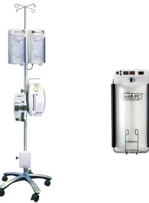
Three types of rapid fluid infusers are used at Stockholm South General Hospital, the Fluido Pressure Chambers (The Surgical Company BV, Amersfoort, Netherlands),
14
the AutoPC (AceMedical, Seoul, Korea) and the Automatic Pressure infusor (Mallinckrodt Pharmaceuticals, Dublin, Ireland).
The Fluido Pressure Chamber (figure 4) is used at the anesthesia and intensive care unit, ER and the obstetrics and gynecology department. The Fluido Pressure Chamber is suitable for 500ml and 1000ml fluid bags. It consists of a dual chamber configuration with a common pressure regulator and individual manometers. The chambers have two bag hangers at different heights for the different fluid bag sizes. To avoid overpressure, an overpressure relief valve is included, set at 300 mmHg. The chambers are connected to the Fluido Compressor for pressurized air supply. The system is used in combination with the Fluido Warming System for warming the fluids to body temperature and the Fluido Airguard System for detection of air in the tube. The Fluido Irrigation Set is a tubing system used to connect all the systems.
Figure 4. From left to right, the Fluido Pressure
Chambers and the AutoPC
Mallinckrodt Pharmaceuticals Automatic Pressure infusor is used at the anesthesia and intensive care, ER and the obstetrics and gynecology. The system is driven by compressed air from the hospital wall pressurized gas outlets and can deliver a maximum fluid pressure of 300 mmHg. The system is an IV pole mountable and consists of a single chamber configuration, a pressure regulator and a manometer. The product is available in a 500 ml and 1000 ml fluid bag compatible version and the chamber doors have one bag hanger at the top.
15 The AutoPC (figure 4) is used at the urology department. The AutoPC is an IV pole mountable electrical pressure infuser with an internal compressor. At the Stockholm South General Hospital they have the single type system with one pressure chamber with a digital display. Pressure can be ranged between 100 mmHg to 300 mmHg and the chamber is available in 250 ml, 500 ml and 1000 ml fluid bag compatible versions. The system has an alarm when the pressure goes 20 mmHg over/under the set pressure. The chamber has one bag hanger at the top and two metal fingers at the bottom to slide the fluid bag behind.
The new design was to be a refinement of an already existing product so observing the customer using the described products was another plausible method of determining requirements. A request to participate in the OR during a surgery was accepted. The working conditions and environment in the OR was observed as well as how the rapid infuser is used in its real context.
To further understand the customers’ experiences and issues, the rapid infusers available at Stockholm South General Hospital were borrowed together with fluid bags of different sizes. The systems were set up and the safety and quality of the products were tested and evaluated. Positioning of fluid bags of various sizes in the chambers was tested. The infusion, inflation and deflation time was measured and the dimensions of the systems were noted. The user friendliness of the products was considered and noted during these tests.
The results from the interviews and product testing were analyzed, clarified and translated into so called "need statements" according to Ulrich and Eppingers method [19]. Personal values were suppressed and the raw data was interpreted into concrete statements describing customers’ needs.
Step 3 - Determine relative importance of the requirements
The interview participants were contacted and consulted for the ranking process of the requirements. They rated the requirements on a scale of 1 to 10. The results from the different participants were in good agreement with each other so the average for each requirement was calculated and used in the QFD matrix [17].
Step 4 - Identify and evaluate the competition
A literature study was conducted for the competitive analysis. The search engine Google was used for finding all available products on the market. Different combinations of the following words were searched: rapid, pressure, pressurized, infuser, infusor, transfusion, chamber, fluid, blood, irrigation and pump. For gathering of material concerning existing products, a few of the manufacturing and sales companies were also contacted for manuals etc.
16
Step 5 - Generate engineering specifications
As many engineering requirements as possible were generated in this step, and help was taken from a checklist listing all major types of engineering specifications [15]. The developed engineering requirements were then marked with the symbol “↑” or “↓”, to tell whether more or less of the requirement would be good.
Step 6 - Set up technical targets for the product
The engineering specifications were related to the customer requirements and graded with 9, 3, 1 or blank, and the center part of the matrix was filled out.
Step 7 - Set engineering specification targets and importance
The specifications’ importance was calculated by multiplying the importance weighting from step 3 with the relationship values from step 6 and summing these values for each engineering specification. Then the values were normalized and also noted in the QFD matrix.
For the next part of this step, obtaining of all the products for the competitive analysis was needed for measurement of all the engineering specifications. Unfortunately since obtaining of all the products on the market was not a possibility; this step could not be carried out.
Step 8 - Identify relationships between engineering specifications
The engineering specifications that were dependent on each other were marked with a “+“ if the specifications had a positive effect on each other and with a “-“ if it was negative.
5.2 P
ROTOTYPING5.2.1
I
DEAG
ENERATIONBrainstorming sessions were carried out individually but also with students and peers in the same field of study. Discussions concerning various ideas also took place with the external supervisor. In the initial phase brainstorming sessions were conducted to explore general solutions and ideas. Further on, the idea generation sessions were focused on specific features and detailed solutions. Specifications that acquired high ratings in the QFD matrix received extra focus during these sessions. The QFD also raised awareness regarding existing solutions and these were considered during the idea generation.
During this phase the market was also explored for components and solutions that could be needed and implemented in the new design. E.g. accessibility, alternatives and cost were considered during the search and generation of a plausible solution.
17
5.2.2
C
OMPUTERA
IDEDD
ESIGNThe choice of concept and design solutions was made in agreement with the supervisors. Initially several hand sketches were made to examine and analyze different design solutions. To design the prototype, the 3D CAD program for mechanical constructions, SolidWorks (Dassault Systemes, Velizy, France) was used. Within this program a 3D prototype and technical drawings were created. Measurements of fluid bags at the Stockholm South General Hospital lead to dimensioning of the chambers.
The users and the situations in which the device is going to be used were constantly considered when developing the control panel. Also here, several hand sketches were made in forehand to examine and analyze different designs. Clear explanations and markings were considered in order to avoid misunderstandings and errors during handling.
18
6 R
ESULTS
The results from the different phases and the methods implemented are presented and described in this section. Material regarding the interviews mentioned in this section can be found in the appendix B.
6.1 Q
UALITYF
UNCTIOND
EPLOYMENTThe final result of the QFD matrix is illustrated in figure 5. The results from each step of the QFD method will be further described in detail as follows.
Step 1 - Identify the customers
In this case the customers relevant for this study were identified as the healthcare personnel at the anesthesia and intensive care unit, obstetrics and gynecology and urology department and furthermore the biomedical engineers at the hospital. The following customers were identified and interviewed:
Gunilla Karlernäs - nurse anesthetists and medical equipment coordinator. She works at the anesthesia and intensive care unit and has been working at Stockholm South General Hospital since 1977.
Ulriqa Edin - nurse anesthetists and medical equipment coordinator. She has worked at the anesthesia and intensive care unit at Stockholm South General Hospital for 12 years.
Ingela Vestin - nurse anesthetist and has worked at the anesthesia and intensive care unit at Stockholm South General Hospital for 31 years.
Maie Zetterström - worked as a nurse for 34 years and nurse anesthetists for 10 years. She works at the obstetrics and gynecology division at Stockholm South General Hospital.
Anna-Lena Holmström - surgical nurse at the division of urology and has been working at Stockholm South General Hospital for 16 years.
Anders Arstrand - biomedical engineer and has worked at Stockholm South General Hospital for two years, whereof one year with rapid infusers.
Daniel Eriksson - biomedical engineer and has worked at Stockholm South General Hospital with rapid infusers for five years.
19 Figure 5. The result of the QFD house of quality matrix
20
Step 2 - Determine the customers’ requirements
The interview results from the participants were in good agreement with each other and indicated an evident demand for a new product with improved quality, functionality and usability. The answers from the interviews can be found in appendix B. The experienced problems will be described in this section to provide an understanding of the current situation and highlight the problem areas.
In the OR the personnel needs to be able to move around easily and the equipment should preferably be movable in case of situations requiring rearrangement of the patient or the OR equipment [20].This was one of the mentioned problems with the pressurized air outlet connected infuser. The pressurized air outlet connected infuser’s air tube has a diameter of 140mm and the personnel considered it to be substantially obstructing and inconvenient. All the participants preferred the compressor driven construction that has a long power cord to solve this problem so that the system can be moved during the procedures. Nevertheless, when the device is close to the outlet the rest of the power cord is hung up or ends up on the floor. This is an identified hazard and there have been accidents in the OR due to power cords on the floor.
The conditions in the OR and the ER are often critical and it is a challenging environment for the hospital staff. Stress is constant for personnel working with critically ill patients [21]. The work pace is very high and the risk for error is always present and the personnel working with critically ill patients must be highly qualified and experienced. When a patient with e.g. massive hemorrhage is brought in, efficient and rapid fluid resuscitation is a crucial and acute task and the fluid bags need to be rapidly and easily installed in the chamber to start the infusion. The larger fluid bags at the hospital do not conform to the majority of the pressure chambers. This impedes the closing of the door, causing situations where the bag is pinched between the door and the chamber base and in worst cases causing the fluid bag to rupture. These situations when e.g. a blood bag ruptures in the OR are distressing and distracting for the personnel.
The chamber cannot have any protruding objects that can cause direct point pressure. This fact causes problems constructing an adequate bag hanger inside the chamber. The personnel experienced difficulties in hanging up the bag inside pressure chambers, and some nurses skip this step and try to hold the bag in place and quickly shut the door, even though the chambers depth are not constructed for simply placing the fluid bag inside, increasing the risk of the bag being placed incorrectly and rupturing, resulting in additional stress and time delay.
21 Furthermore, no part of the spike or catheter should be inside the chamber as the pressure in the chambers can push the spike out. Thus the fluid bag should always be positioned close to the bottom of the chamber just above the passage for the catheter. Consequently the bag hangers’ height needs to be compatible with different bag sizes, which hasn’t been the case with the existing devices.
Critical causes of health care-associated infections are inadequately cleaned, disinfected, or sterilized medical devices [22]. Rough surfaces, crevices and narrow lumens should be avoided since they make cleaning and disinfection of the equipment difficult. Blood contamination of the rapid infusers due to blood bag rupture was one of the mentioned issues. Most of the rapid infuser systems have hinged doors with many cracks making the cleaning process problematic. Due to this difficulty the devices contaminated with blood after a blood bag ruptures have to be sent to the biomedical engineers to be disassembled and cleaned thoroughly.
Another reported issue has been explosion of the internal inflation bags that are as previously mentioned situated inside the chambers. Situations have occurred during preparation for a rapid infusion treatment, when the nurses have turned on the system and shortly after become preoccupied with something else and accidentally left the chamber doors open. When this happens the internal inflation bag keeps growing and finally explodes over the patient and staff.
It is known that the pressure of the infusion device must not exceed 300 mmHg. Exceeding 300 mmHg may negatively affect the blood cells or result in bag rupture. An interesting fact that was discovered during the interviews was that the nurses at the anesthesia and intensive care unit, ER and obstetrics and gynecology department don’t use pressures under 300 mmHg either. As a standard routine the pressure chambers are always set on 300 mmHg and they avoid regulating the pressure. The nurses say that when patient condition is stabilizing they regulate the infusion rate manually with the roller clamp. They leave the pressure infuser always set on 300 mmHg so that the system is ready to be used when needed, to reduce the number of tasks and increase efficiency.
A time-consuming task that was discovered during an interview and during some test sessions with the different systems, was the manual deflation of the internal inflation bag once an e.g. blood bag is emptied and has to be exchanged. Once the internal inflation bag is fully inflated and the operating fluid bag emptied the nurses open the chamber to put in a new bag, but first they had to manually press out all the air out of the internal bag.
As previously mentioned the Fluido Pressure Chamber is used in combination with the Fluido Warming System, Fluido Airguard system and the Fluido compressor. Each of these four systems has a power button. For example when an acutely ill
22
patient comes to the ER in acute need of fluid transfusion, turning each system on individually is considered time-consuming and redundant. In addition some of these power buttons have also been referred to as inconveniently placed, for example the Fluido compressor’s power button is positioned under the device making it impossible to localize without placing your hand under and searching for it.
The described problems were analyzed, clarified and translated into the following need statements:
Functionality
⋅ Electrical or self-provided system ⋅ Operates at 300 mmHg only
⋅ Detects air and temporarily stops the flow ⋅ Movable system
⋅ Deflation system Structure
⋅ Compatible with standard fluid bags ⋅ Easy bag positioning
⋅ No sharp or protruding component Usability
⋅ Ease of access to all switches ⋅ Ease of use
⋅ Rapid and efficient ⋅ User friendly interface
Personnel and patient safety ⋅ Ease of sterilization
⋅ Operates only when chamber doors are closed
Step 3 - Determine relative importance of the requirements
The requirements were rated as follows and can be found in the second column from the left in figure 5:
Compatible with all standard fluid bags – 10p Operates only when chamber doors are closed– 10p Detects air and temporarily stops the flow– 10p Easy bag positioning – 9p
Ease of sterilization – 9p Ease of use – 9p
23 Movable – 8p
No sharp or protruding components – 8p Rapid and efficient system – 8p
Electrical or self-provided system – 7p User friendly interface – 7p
Deflation system – 6p
Ease of access to all switches – 6
Step 4 - Identify and evaluate the competition
The following products were identified and included in the evaluation: A. Fluido Pressure Chambers (The Surgical Company BV, Amersfoort,
Netherlands)
B. Automatic Pressure infusor (Mallinckrodt Pharmaceuticals, Dublin, Ireland) C. AutoPC (AceMedical, Seoul, Korea)
D. Level 1 System 1000 (Smiths Industries Medical Systems, Rockland, USA) E. Ranger Pressure Infusor System Model 90032 (3M, Minnessota, USA) F. Ranger Pressure Infusor System Model 14500 (3M, Minnessota, USA) G. The 1-Liter Pressure Infuser Irrigation Pump (Conmed Corp., Utica, USA) H. The 3-Liter Pressure Infuser Irrigation Pump (Conmed Corp., Utica, USA) I. Infuser Irrigation Pump (Lagis, Taichung, Taiwan)
J. Fluid management system 2000 (Belmont Instrument Corp., Billerica, MA) The relationship to the customer requirements can be found in figure 5 in the right column. The measurements and depths of the chamber could not be attained for a few products, thus the requirement “Compatible with all standard fluids” was excluded from the evaluation for all the products.
Product J, the Fluid management system 2000 (FMS 2000), was the only identified product that had a construction and design different from the chamber design. The fluid bag catheter is connected directly to the FMS 2000 and pressure is applied by a roller-pump. The system is coupled with an induction heater and two air detectors. The customer experiences and requirements are based on the chamber design
products, thus many of the user customer requirements couldn’t be related to the FMS 2000.
Step 5 - Generate engineering specifications
The following engineering specifications were generated: ⋅ System dimensions ⋅ Chamber dimensions ⋅ Weight ⋅ Cord/tube length ⋅ Set up time ⋅ Inflation time ⋅ Deflation time
24
⋅ Time to learn system ⋅ Time to change bag ⋅ Usability
⋅ Reliability ⋅ Safety ⋅ Cost
Step 6 - Set up technical targets for the product
The results of the engineering specifications relation to the customer requirements can be found in the center of the QFD matrix in figure 5.
Step 7 - Set engineering specification targets and importance
The result of the calculation of the specification importance is presented below, in descending order.
1. Safety 2. Set up time 3. Usability
4. Time to change bag 5. Cost
6. Weight 7. Reliability
8. Time to learn system 9. Deflation time 10. System dimensions 11. Inflation time
12. Chamber dimensions 13. Cord/tube length
Step 8 - Identify relationships between engineering specifications
Only one negative relationship between the engineering specifications was found and four positive (for details see the roof of the house of quality in figure 5).
25
6.2 P
ROTOTYPING6.2.1
C
OMPUTERA
IDEDD
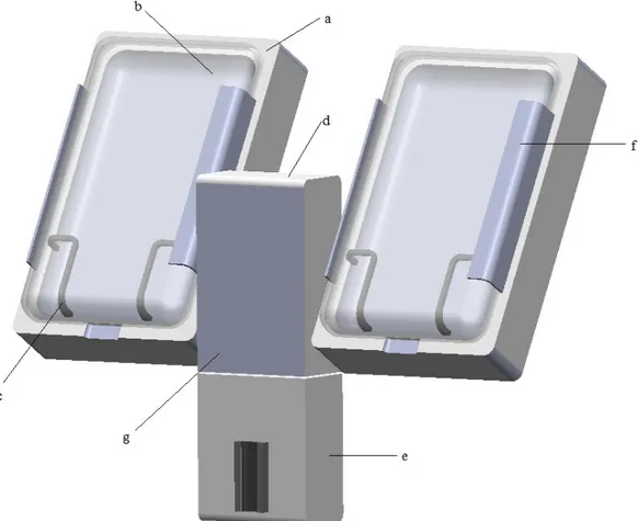
ESIGNThe presented CAD design is an IV pole mountable device intended for pressurizing fluids to be rapidly infused. The detailed prototype was created using Solidworks.
Figure 6. The final CAD design of the rapid infuser including a) chambers, b) doors, c)
support fence, d) compressor case, e) air detector case, f) hinge and g) control panel position.
26
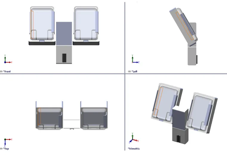
Figure 7. The final CAD design from different angles
6.2.2
D
ESIGNS
PECIFICATIONSAs illustrated in figure 6, the final design consists of two chambers (a) with doors (b), a case for the compressor (d) and one for the air detector (e). Improvement and development of an air detector system was not included in this study. However a proposal of the positioning of the air detector was made, in order to emphasize the design solution of a system with all required components in one. Thus the product has one power button for the whole system.
The pressurizing chamber comprises a base and a door. The base has an internal bladder bag connected to a compressor. The base and door are cavity formed, having the same shape as a fluid filled bag when hanging in a vertical position. Measurements of variously sized fluid bags led to dimensioning of the chambers. In order to fit all standard fluid bags and facilitate positioning of the bag, the chambers
27 have a length of 300mm and width of 18mm. Because of the conformance of the chamber to larger fluid bags, there will be no need to manipulate the fluid bag to close the door, decreasing the risk of rupturing the bag and saving time. The door and the base are joined together with a strong two piece hinge, covered by a flexible plastic rail, thus reducing the number of open cracks and crevices.
Two sorts of material are used, plastic and rubber. The surfaces are smooth and nonporous to prevent trapping of biologic material and are made out of plastic. The chamber doors are designed in transparent plastic to enable visual inspection of fluid levels etc. To enable positioning of the bag in the bottom of the chamber a hanger construction was rejected. Instead two rubber support fences (c) were designed and placed on each side of the chamber. The chambers are also tilted back 30° for further facilitation of fluid bag positioning.
As mentioned the device is compressor driven. Most of the operating theatres at Stockholm South General Hospital have ceiling pendant arms with electrical outlets and according to the hospital staff the plans are to install them in all ORs. Therefore the power cord of the prototype is situated on the upper part of the backside of the device, to be as close as possible to the ceiling arms.
A long power cord to enable movability is preferred but the issue was when the power cord was on the floor, introducing fall hazards. To reduce this risk, but retain movability an internal retractable power cord reel is to be mounted on the back side of the device. Different constructions and products on the market were explored and the DuraReel medical cord reel (Ametek, Feasterville, USA) specifically designed for medical applications is a suggested product for this design. All contact surfaces are molded with an antimicrobial additive that does not wash off or diminish over time and the surface of the reel is made smooth to facilitate cleaning [23]. The durable 19.1-centimeter diameter reel fits a 3-meter cord. The reel enables extension to a desired length and when not in use smoothly retracted into the housing. There are optional mounting configurations and a recommended mounting bracket is illustrated in figure 8, as well as further measurement details.
28
Figure 8. Recommended mounting bracket and measurement
details of the DuraReel medical cord reel [23]
To make the system more efficient and convenient a vacuum pump is to be installed for quick deflation of the internal chamber bag in between fluid bag changing. This saves time and requires less manual work when changing fluid bags.
The result of the detailed control panel (g) can be found in figure 9. The power button illuminates when pressed and a green indicator notifies the user that the system is on. Once the system is on, the user can rapidly inflate or deflate a chamber, and once again a green LED notifies the user about which side is operating and if it is inflating or deflating. The system only operates at 300 mmHg during inflation. If there is a system fault and the pressure goes above 310 mmHg or under 290 mmHg the arrow above respectively under the digital pressure display will be illuminated. Besides the visual alarm there is also an audible alarm notifying the user of the system fault. In case of a system fault the system should be shut down and troubleshooting measures should be taken.
29 Figure 9.a) Rapid infuser panel design b) Activated buttons. A green indicator notifies the
user that the system is on. A green indicator notifies the user that the chamber is inflating/deflating. An red indicator notifies the user if the pressure goes above/under 300
mmHg.
The inflation or deflation of a chamber can only start if the chamber door is closed. A power switch is installed to cut the circuit/power supply when the door is open. A D2D door Interlock Power Switch (Omron, Kyoto, Japan) with minimum contact gap of 3 mm is suggested. This product has a pull-on lock model for easy maintenance. This enables power supply when the door is open by pulling out the plunger, when performing e.g. inspections and repair [24]. By closing the door after maintenance inspection, the switch will resume the normal momentary operation.
30
7 D
ISCUSSION
The general purpose of this master thesis was to develop a design of a new improved rapid infuser device with suggested features and modifications that facilitated the hospital staffs’ work and consequently could improve patient outcome.
The QFD method was chosen because it was industrially proven to be beneficial and could be effectively realized with the given resources and time. QFD clarified the current solutions and their weaknesses and facilitated the development of a design that met the customer requirements. The method described the design problem systematically and formed the basis for the development of an improved design. User involvement was an essential and significant part of the QFD method and thus to this project. The results from the QFD method indicated an evident demand for an improved product.
During the second step of the QFD method several comprehensive interviews were conducted and served as the main fact collection method of this thesis. Several previous reports have emphasized the value of using rapid infusion systems to administer large volumes of fluids to patients, however they also have shown that many of the safety issues and limited reliability undermines the products value [25, 26]. This fact was verified during the interviews. The interviews contributed to a greater understanding of rapid infusion systems and their weaknesses. All the customer requirements were addressed in the final result; however the results from the QFD indicated how much effort and time should be devoted to each requirement. Since safety was the highest rated engineering specification, a lot of time and effort was dedicated to solutions that could affect the safety of the system positively. A compressor driven system was chosen to avoid the inconvenience and obstruction of an air tube. Furthermore the conclusion was drawn that the rapid infuser is always used in combination with an electrical fluid warmer and thus a power cord is unavoidable and always present for the entire system. The safety issues with the compressor driven system was the power cord storage. To reduce the risk of personnel accidents in the OR a safe and convenient cord management was realized by the use of a retractable cord reel.
A health hazard affecting patient and personnel safety is health care-associated infection. This is a present health hazard due to the blood contamination of the rapid infusers because of the situations that lead to blood bag rupture. Initially, addressing these problems leading to fluid bag rupture the infection risk could be reduced. Solutions involving fluid bag positioning and chamber dimensioning were studied. One of the strengths of the new design is its compatibility with the different bag sizes,
31 making positioning of the bag and closing of the door easier. The solution presented was tilting back the chambers. To further facilitate the fluid bag positioning, the hook design, that most of the systems on the market have today, was rejected and instead two rubber support fences were implemented on each side of the chamber. This is considered a promising design solution and can reduce the risk of the bag being pinched between the door and the chamber base and in worst cases causing a blood bag to rupture, a very distressing and distracting situation for the personnel. These solutions are expected to consequently save time and work for the nurses and the medical equipment department. Nonetheless, the risk for bag rupture cannot be considered absent and thus the surface and materials were designed and chosen to facilitate cleaning and disinfection.
Another safety aspect is the detection of air bubbles in the IV tube. Air embolism can be a life threatening event and a high level of vigilance is of great importance for rapid diagnosis and treatment of this condition [27]. A study by Comunale [26] stated that due to the lack of air-detection systems on rapid infusion devices, air infusion remains a potentially hazardous situation. Only three of the systems available today were sold with an integrated air detector device, the Fluido Pressure Chambers, the Level 1 System 1000 and the Fluid management system 2000. Despite the fact that the improvement and development of an air detector system was not included in this project, a proposal of the position was made in the CAD design, to present the suggestion of integrating this device in the system due to its importance for patient safety.
The second and third highest rated engineering specifications were the set up time and usability. An aspect that involved all three highest rated specifications was the rapid infuser rapidity and efficiency, and thus got additional attention and time. The conditions when the apparatus is needed are often acute and critical and the patient’s life is often dependent on the system set up speed. Factors that slowed down the process were, turning on the system, adjusting pressure and bag positioning. As a standard routine the pressure chambers were according to the nurses always set on 300 mmHg so that the system was always ready to be used and to reduce the number of tasks. Nevertheless it was discovered that all rapid infusers on the market today except one, the Ranger Pressure Infusor System Model 1450, had adjustable pressure. With this in mind the new rapid infuser is designed to only operate at 300 mmHg during inflation, to eliminate the risk of changing the pressure and guarantee a more efficient system. To further improve efficiency and usability, the product has one easy accessible main power button for the whole system.
Furthermore the usability was considered throughout the entire development process. It was important to develop an interface that was user friendly and intuitive. The interface was designed so that it is hard to make mistakes, even during stressful situations. Another vital part of designing the interface and safe devices was the implementation of the alarms. A good alarm should get attention without startling
32
people [29]. Furthermore the alarm needs to be easy to locate and the meaning of the alarm should be clear to the medical staff. Thus the alarm for too high or low pressure, were made as arrows and had a red color to signalize that something is wrong. In a later stage when a prototype can be manufactured, tests need to be run to evaluate how the users experience the alarms and the interface to ensure efficiency and usability.
The competitive analysis raised awareness regarding existing solutions and improvement possibilities as well as enabling the announcement of the most optimal existing product today. The Ranger Pressure Infusor System Model 14500 (3M, Minnesota, USA) scored the highest ratings in fulfilling customer requirements and this product is proposed as the most optimal system on the market today.
7.1 R
ESEARCHL
IMITATIONSThere were many benefits in involving the users in the development process. Nonetheless, parts of the collected material must be considered as subjective, e.g. the interview responses and consequently the analysis. The results from the evaluation of are partly dependent on the users' knowledge and skill. It can be difficult to know whether an issue with the equipment derives from the poor user knowledge or the products itself. However, most errors are due to inappropriate designs for user interaction, rather than mechanical failures [28]. The study is solely based on the participants’ perceptions, but the aim has been to consistently take into account this limitation. The compensation consisted of an open approach to negative results and an endeavor to cover a wide range of the participants’ experiences. Thus, further research may be needed to investigate and include objectively measurable issues. Practically all the interview participants mentioned the same issues and were in very good agreement with each other concerning requirements for a new product and the ranking of them. Nevertheless a limitation of this study is that it involved a relatively small sample of the primary users from one hospital. Even though a market research was performed and included in the development process; the interview material could only be based on the products the participants had used. In order to enhance the study's validity the study sample should be enlarged and include interview participants from different hospitals.
7.2 F
UTUREW
ORKA new improved rapid infuser device can benefit the patient significantly, but it is also beneficial for the hospital. A safer, more reliable and efficient rapid infuser may lead to fewer complications, earlier recovery and discharge, consequently reducing costs and improving economics for the hospital. A more reliable and efficient system
33 will save time and additional work, further reducing hospital costs. Although the final design is expected to be reliable and safe, as any new product the device may carry unpredicted risks. Thus, a risk analysis should be performed to justify the potential benefits over the potential risks.
When selecting components and material the economics is a crucial factor. The final product must have a reasonable price without risking product quality or patient safety. Another important aspect for further work with this device is environmental sustainability. A sustainable design is beneficial for the environment and society, as well as economic vitality. Sustainability should be regarded during all stages of the product life. It should be considered during e.g. the material selection and manufacturing of a prototype, but as well as e.g. packaging and transportation in future phases. The choice of machinery and electronic components were not included in this study, but for future research, energy efficiency, environmental impact and cost should be considered when choosing components.
The placement of a new rapid infuser on the market requires adhering to several regulations and directives. To place this product on the market in EU the requirements of the Medical Device Directive (MDD) must be fulfilled [30]. Every nation also has national regulations for medical devices that are based on EUs directives. The main Swedish legislation regulating medical devices is the The Medical Devices Act (1993:584) and The Medical Devices Ordinance (1993:876) [31]. In Sweden the Medical Products Agency (MPA) is the national authority responsible for implementation and monitoring of the directives. MPA's
responsibility includes surveillance of the development, manufacturing
and marketing of medical device. During future development projects these regulations and directives must be considered and implemented.
This study can be viewed as a pilot study and based on the presented results it can serve as a basis for further development. Finally the identified areas for further study are concluded as:
• Investigate and include objectively measurable issues
• Further investigate the demand and requirements with a national perspective • Study the electronic design and the choice of compressor and vacuum pump • Perform a risk analysis and a cost-effectiveness analysis
• Perform a detailed study of relevant directives and regulations • Manufacture a prototype for testing and further evaluation
![Figure 1. Body fluid compartments, a) distribution of body solids and fluids in an average adult female and male, b) exchange of water among body fluid compartments [6]](https://thumb-eu.123doks.com/thumbv2/5dokorg/5429472.140014/19.892.215.664.681.974/figure-compartments-distribution-solids-fluids-average-exchange-compartments.webp)
![Figure 2. Schematic view of the house of quality matrix [15]](https://thumb-eu.123doks.com/thumbv2/5dokorg/5429472.140014/23.892.281.550.272.531/figure-schematic-view-house-quality-matrix.webp)
![Figure 3. Examples and guidelines for translation into need statements [16]](https://thumb-eu.123doks.com/thumbv2/5dokorg/5429472.140014/24.892.154.736.129.429/figure-examples-guidelines-translation-need-statements.webp)
![Figure 8. Recommended mounting bracket and measurement details of the DuraReel medical cord reel [23]](https://thumb-eu.123doks.com/thumbv2/5dokorg/5429472.140014/42.892.275.573.113.430/figure-recommended-mounting-bracket-measurement-details-durareel-medical.webp)
