TOWARDS APPLYING THE BOOTHROYD, DEWHURST AND KNIGHT METHDOLOGY FOR COST ESTIMATION ON FIBRE COMPOSITE MANUFACTURING – A THEORETICAL
APPROACH
Fredrik Henriksson1 and Kerstin Johansen1
1Machine Design, Department of Management and Engineering, Linköping University
fredrik.henriksson@liu.se
Increased usage of carbon fibre composite poses challenges for the automotive industry; one is to manage carbon fibre composites within the product development process. This paper combines knowledge in design engineering, material science and production technology, aiming to bridge these domains. The study indicates that mass production methods suitable for carbon fibre have several factors in common with traditional polymer production methods. Thus, it is possible that DfMA methods for traditional polymer production can be adjusted for carbon fibre composite production. The result is summarised in a table aiming to facilitate engineering decisions related to cost estimations for composite moulding.
Keywords: DfMA, carbon fibre composites, automotive, design engineering
1. BACKGROUND
Carbon fibre composite is known as one of the light-weighted materials that increase in use in today’s products. Especially, products where weight is related to energy consumption, such as automotive products. Since McLaren introduced the first F1 car built in carbon fibre composite in 1981 (BBC Technology, 2014), carbon fibre reinforced polymers (CFRP) has been usually been used for exclusive sport cars and racing cars. Since components in CFRP can be significantly lighter than responding components in steel or aluminium due to their higher Young’s Modulus-to-density ratio, such fibre reinforced plastics are materials that are of great interest when weight is an important quality in the end product. Carbon fibre composites used as structural elements entered broad automotive industry (spanning outside of niche vehicles) when BMW released the i3, their electrical car with a carbon fibre composite chassis (BMW 2014a, 2014b). A similar layout is used by BMW in their i8 car as well (BMW 2014c), and according to BMW representatives the material will be used in their coming internal combustion engine powered cars as well (Auto, Motor & Sport, 2014).
The automotive industry is at the moment very interested in the topic of weight reduction in order to reduce
CO2-emissions for internal combustion engine-powered cars (European Commission, 2014 & Lotus Cars, 2014)
and range for battery electric vehicles (Metro News Canada, 2014 & Aluminum.org, 2014). For internal combustion-engined cars, a reduction of 10% in weight can result in 6-8% improved fuel economy (Office of Energy Efficiency and Renewable Energy, 2014).This interest can also be seen in different weight-saving studies and projects currently performed by automotive companies, consultants and government agencies all over the world (Green Car Congress, 2014 & Chicago Tribune, 2014).
Composite materials have a principle composition of a continuous phase (often called the matrix) and a reinforcing phase (fibres etc). When looking further into the reinforcing phase, two factors become evident; the material and the architecture. The architecture can be of two types; discontinuous (particles or short fibres) or continuous (unidirectional or textiles). (Friedrich et. Al, 2012)
Based on the material properties, it should be recognized that carbon fibre composites are not the same as classical automotive materials such as steel or aluminium. The anisotropic nature (Damberg, 2001) of fibre composite materials give the designer another factor to take into consideration when designing; this added complexity could make it more complicated to optimize the design of components in composites, assuming that there is a relation between the number of design parameters and design complexity. Also, the production process
could affect the properties of the end product to a much higher degree in composite materials than in classical automotive materials, since the composite material is “built” in the production process rather than formed (Damberg, 2001). That means that there are at least three major factors shaping the properties of a fibre composite product; matrix material, reinforcing material and reinforcement geometry (Friedrich et. al, 2012). Since components in CFRP can be significantly lighter than responding component in steel or aluminium, due to their CFRP’s higher Young’s Modulus to density ratio, such fibre reinforced plastics are materials that are of great interest. This poses a number of new challenges for the automotive industry; one of them is how to manage carbon fibre composites throughout the product lifecycle. Finding a way to reduce cost for composite reinforced components may affect the automotive industry greatly, and a first step towards reducing cost could be to get quick information about approximate manufacturing costs already within the design phase. Also, getting a way of comparing component cost regardless of materials used could help design engineers when choosing materials. Using already established ways of comparing materials may help bridge the gap between composites and classical automotive materials, since it will be treated as a material among many others.
Therefore, this paper is based on a literature review, combining existing domain knowledge in design engineering, material science and production technology in order to bridging these domains. The purpose is to identify ways to combine these in a way to facilitate composite design and manufacturing in the automotive industry using the CFRP method.
2. METHOD
The performed and presented literature review, which this paper is based on, combine existing domain knowledge in design engineering, material science and production technology. The aim is to suggest a conceptual way of comparing component cost regardless of materials used could help design engineers when choosing materials early on in the NPD process. These domains are in this paper combined into three major topics; fibre composites, DfMA (Design for Manufacturing and Assembly) and knowledge processes in New Product Development (NPD), and presented as these in order to ease reading, as can be seen in Fig. 1.
Fig. 1. Intersections of domains and topics in paper.
The literature is mainly selected from the production methods related to carbon composite described by Gay and Hoa (2007) along with Damberg (2001), and the Design for Manufacturing and Assembly (DfMA) moulding design process described by Boothroyd, Dewhurst and Knight (2011). These books are complemented by other sources, such as more recently published academic papers and industrial related publications in order to present the latest trends regarding composite usage in i.e. automotive applications.
Design engineering and the NPD process is described as a knowledge process, and theories about knowledge capture and reuse within the product development process are presented. Different methods for carbon fibre composite manufacturing are explored and combined with identified areas of knowledge that can be reused in a NPD process. The DfMA method is used for exploring which aspects in the carbon fibre composite manufacturing affecting which DfMA parameters.
3. THEORETICAL FRAMEWORK 3.1 Product development as a knowledge process
According to Ullman (2010), the design and product development process can be described as a knowledge-creating process. All through the design process, the designers’ knowledge regarding the topic of their design increases. Ullman also states the design process paradox; the fact that design freedom shrinks as the design process moves forward, while design knowledge broadens as the process moves forward (Fig. 2). This is a paradox that needs to be managed in order to minimize redundant work and make the design process as efficient as possible.
Fig. 2. The design paradox, as by Ullman (2010).
Cooper (2003) refers to Majchrzak et al summarizing seven factors affecting the probability of knowledge being reused in the New Product Development process:
1. The knowledge of the recipient 2. The search strategy of the recipient
3. The willingness of knowledge-sharing of the source 4. The relationship between the source and the recipient 5. The ability to adapt previous knowledge
6. The presence of a third party whom establish credibility 7. The possible existence of shared artefacts
According to Zhang et al (2011), process and task knowledge are vital parts of design knowledge and therefore the Cooper/Majchrzak factors are assumed to be applicable on these types of design knowledge.
DfMA (Design for Manufacturing and Assembly) is a methodology that has become established in the automotive industry (Boothroyd Dewhurst Inc, 2014a & 2014b). One DfMA tool available is the cost estimation model (Boothroyd, Dewhurst & Knight), which gives the designer a possibility to estimate relative production cost from different designs.
Cost-focused models for design in fibre composite materials, focusing on the aerospace industry, have been presented before (Kaufmann, Zenker & Åkermo, 2010 & Geiger & Dilts, 1996). This indicates that cost-focused design tools may be useful for composite design. Though, it should be noted that these tools have not yet been generally applied to the automotive industry.
3.2 Fibre composite materials
Fibre composite materials have several positive qualities for automotive use compared to steel, where a significant weight reduction (20-40%) and corrosion resistance are two (Friedrich et. al, 2012). Fibre composites such as CFRP (Carbon Fibre Reinforced Polymers) can be used in automotive products in many ways, examples are passenger cells (BMW, 2014b & 2014c) and wheels (Knox, 2012).
The major fibre composite component manufacturing techniques suitable for mass production according to Gay & Hoa (2007) are compression moulding, resin injection moulding, moulding by injection of premixed and moulding by foam injection.
3.3.1 Compression Moulding
In compression moulding, two moulds (one male and one female) are used. Between the moulds the composite structure and resin is placed and a pressure is placed on the whole assembly forcing the two moulds together and compressing the composite in between while the resin cures and the component is done. (Gay & Hoa, 2007) 3.3.2 Resin Injection Moulding
Resin injection moulding also uses two moulds, but while the composite structure is placed between the moulds before assembling the system, the resin is injected into the mould when it is assembled. (Gay & Hoa, 2007) 3.3.3 Moulding by Injection of Premixed
Moulding by injection of premixed is a variation of traditional injection moulding in plastic materials, but where fibre reinforcements have been mixed into the plastic. The plastic resin here could be either thermoset or thermoplastic resin; the production of these two will differentiate in the placing of the heat source in the mould. When using thermosets, the mould (both male and female) will be heated while the heaters will be placed before the mould if thermoplastics are used. (Gay & Hoa, 2007)
3.3.4 Moulding by Foam Injection
Moulding by foam injection mixes isocyanate, polyol and cut fibres into fibre reinforced polyurethane foam. The isocyanate and polyol are kept in separate systems, where the cut fibres are mixed into the polyol, until they are mixed and directly injected into the mould. Also here, both a male and a female mould are needed. (Gay & Hoa, 2007)
3.3.5 Analysis of fibre composite component manufacturing methods
Of these four production methods, injection of premixed and foam injection are very much like injection moulded plastic production already commonplace in the automotive industry. Therefore, these will not be further investigated in this paper. Compression moulding and resin injection moulding proposes somewhat new steps in the production process; the placement of the reinforcing fibres in the mould before injecting the resin.
A further examination of compression moulding shows that the process can be broken down into four steps (Damberg, 2001):
• Prime the mould with composite structure saturated with resin
• Mould saturation
• Close the mould and apply pressure
• Eject the finished component
Resin injection moulding is quite alike compression moulding, with a few added steps within the moulding process (Damberg, 2001):
• Place resin in transfer chamber • Place composite structure in mould
• Close mould
• Eject resin into mould
• Cure
• Open tool and eject finished component
Both these methods have features in common with classical injection moulding. 3.4 Cost estimation methodology
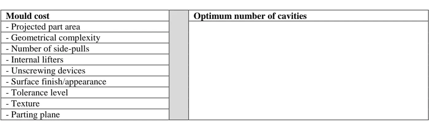
Boothroyd, Dewhurst and Knight (2011) have presented a methodology for estimating injection moulding cost by calculating a) mould cost and b) optimum number of cavities. The mould cost is determined by projected part area (in cm2), geometric complexity, number of side-pulls, internal lifters, unscrewing devices, surface finish/appearance, tolerance level, texture and parting planes (Table 1).
Table 1 Cost estimation for injection moulding according to Boothroyd, Dewhurst and Knight (2011)
Mould cost Optimum number of cavities
- Projected part area - Geometrical complexity - Number of side-pulls - Internal lifters - Unscrewing devices - Surface finish/appearance - Tolerance level - Texture - Parting plane
The difference between classical injection moulding and composite resin injection moulding is the addition of the composite structure. The typical method of adding the composite structure is to by hand add the fibre mats cut into correct shape to fit in a certain way in the mould.
4. ANALYSIS
Referring to Cooper (2003), it would be beneficial to look at adapting methods existing in the automotive industry rather than introducing new methods when looking at cost estimations in composite design. This should aid in the method winning acceptance quicker and making it a more useful tool for designers in the automotive industry.
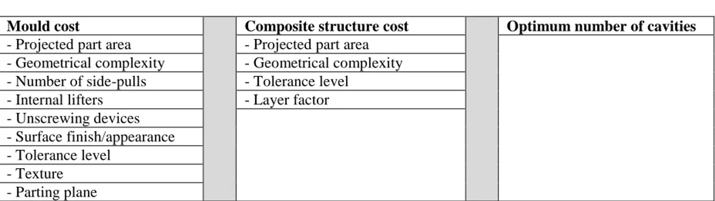
Looking at the composite material processes presented in this paper, the processes regarding adding the composite structure into the mould could be added to the moulding cost estimation. Given the injection moulding cost estimation table presented earlier, and with a composite structure cost added a cost estimation table could look something like Table 2:
Table 2 Suggested cost estimation for fibre composite components, topics.
Mould cost Composite structure cost Optimum number of cavities
- Projected part area - Geometrical complexity - Number of side-pulls - Internal lifters - Unscrewing devices - Surface finish/appearance - Tolerance level - Texture - Parting plane
The composite structure-related processes in composite manufacturing could be seen as determined by firstly two of the factors from the list of mould cost factors described by Boothroyd, Dewhurst and Knight; the projected part area and the geometric complexity. Also, the tolerance level of the composite structure in terms of fibre orientation needs to be addressed since that is one of the property defining factors of a composite component. If the materials’ anisotropic nature has been used by the designer, it is vital that the composite structure is placed correctly in the mould. Finally, a factor describing the number of composite structure layers should be added.
When looking at the described composite material production processes, and the methodology for mould cost estimation, it appears as if the current tools within DfMA (which is used in the industry today and therefore needs less buy-in from the user) could be modified to suit new needs that arise when composite materials enter the mainstream automotive industry. The author’s suggestion is therefore to view moulding costs for composite parts as a result of three factors; mould cost, composite structure cost and optimum number of cavities. The different factors can themselves be divided into sub-processes as described in Table 3:
Table 3 Suggested cost estimation for fibre composite components, detailed.
Mould cost Composite structure cost Optimum number of cavities
- Projected part area - Projected part area
- Geometrical complexity - Geometrical complexity
- Number of side-pulls - Tolerance level
- Internal lifters - Layer factor
- Unscrewing devices - Surface finish/appearance - Tolerance level - Texture - Parting plane 5. DISCUSSION
This method propose a new way of quickly estimating composite parts manufacturing costs, by using established methods used in the industry. It is based on and widens the Boothroyd, Dewhurst and Knight methodology and cost scoring system to include composite structures. However, this method is developed by combining existing domain knowledge in design engineering, material science and production technology and it is a need for practical evaluation. There are uncertainties about which kind of information that is to be viewed in the middle column (describing composite structure cost). As suggested in this conceptual method the information has the characteristics of factors that generate cost. Throughout the literature review, DfMA is identified as a methodology that could be supportive to use for composite materials. The use of composite materials could be supported to a break through into the industry further, if the methodology is applied in the correct way.
This result (Table 3) could aid the engineers incorporating fibre composite materials in the NPD process along with classical materials, using tools that can be applied for several different materials. This would give the automotive industry design engineers further flexibility and ability to adapt to the market in new ways.
DfMA, as a method, was developed for product analysis in the late 1970s and early 1980s (Curtis 1997). At that time carbon composite materials were not widely spread in many industries, such as the automotive industry. Based on this historical perspective, a comparison between moulded polymers and fibre composite materials might not be as relevant as a comparison between metals and fibre composites, since that is example of different material classes that could be exchanged in several types of components. However, although this is a very relevant comment this paper precedes such an initiative. If different materials are to be compared for a specific design, they must be compared equally. Many tools that the authors have found are performing a relative comparison, without presenting absolute cost predictions. In order to make comparisons in these relative tools, it is our view that one must compare results based on the same tool. But is it possible to create cost prediction tools that spans different material classes? That is what this paper is trying to investigate. And based on this literature study, it seems possible that tools can span over different material classes and still be relevant, which would aid designers in making design decisions on a broader information basis.
6. SUMMARY, CONCLUSIONS AND FURTHER STUDIES
Fibre composite materials, such as CFRP, are interesting for the automotive industry due to its ability to lower component weight if used correctly. Lower weight is seen as a way of lowering fuel consumption (for internal combustion engine cars) or prolonging range (for battery electric vehicles). At the moment, a common practice of fibre composite component production is by manual labour, a method not suitable for mass production such as the automotive industry. And since the manufacturing processes suitable for metals are not the same as the ones for fibre reinforced plastics, modifications in design methodology may be suitable.
Current methodology for moulding have many features in common with composite moulding, and it therefore seems like tools for cost estimating moulding could be used as a base for a cost estimation methodology highlighting composite moulding. The main difference between classical moulding and composite moulding is the insertion of the composite structure, and the cost of the composite structure has therefore been suggested as an additional factor in the cost estimation. This factor could be broken down into material costs (structure area) and labour costs (part complexity and tolerance levels), with a layer multiplier added to address the ability to
adjust for multiple layers of composite structure. In the end, this implies that one design tool can be used for comparisons over material classes.
Future studies in this area could be to verify/falsify the validity of the proposed tool and/or the composite structure cost factors, and quantify the different factors. Other future studies could be to implement the tool and study effects on design results. Even future studies could investigate other design tools spanning material classes, and their effect on design decisions.
REFERENCES
Auto, Motor & Sport (2014): http://www.auto-motor-und-sport.de/news/norbert-reithofer-im-interview-neuer-7er-auch-aus-carbon-8333509.html (2014-05-16) Aluminum.org (2014): http://www.aluminum.org/AM/Template.cfm?Section=Home&CONTENTID=29343&TEMPLATE=/CM/ ContentDisplay.cfm (2014-03-17) BBC Technology (2014): http://www.bbc.co.uk/news/technology-12691062 (2014-06-02) BMW (2014a): http://www.bmw.com/com/en/insights/corporation/bmwi/concept.html#lifedrive (2014-07-02) BMW (2014b): http://www.bmwgroup.com/bmwgroup_prod/e/0_0_www_bmwgroup_com/investor_relations/corporate_ne ws/news/2010/MCV_2013.html (2014-03-17) BMW (2014c): http://www.bmw.com/com/en/newvehicles/i/i8/2014/showroom/safety.html (2014-05-11) Boothroyd, Dewhurst & Knight (2011): Product Design for Manufacture and Assembly.
2011
Boothroyd Dewhurst Inc (2014a): http://www.dfma.com/resources/johnson.htm (2014-06-02) Boothroyd Dewhurst Inc (2014b): http://www.dfma.com/resources/panel.htm (2014-06-02)
Chicago Tribune (2014): http://articles.chicagotribune.com/2014-02-17/classified/chi-auto-industry-weight-reduction_1_fuel-economy-aluminum-auto-industry (2014-03-17)
Cooper, L.P. (2003): A research agenda to reduce risk in new product development through knowledge management: a practitioner perspective. Journal of Engineering and Technology Management, Volume 20 Curtis, Mark S. (1997): Boothroyd Dewhurst’s DFMA® & JCB Excavators. IEE 1997
Damberg, H. (2001): Komposithandboken. Industrilitteratur European Commission (2014):
http://ec.europa.eu/research/transport/projects/items/reducing_car_weight_and_cutting_down_greenhouse_g as_emissions_en.htm (2014-06-02)
Friedrich, K. & A.A. Almajid (2012): Manufacturing Aspects of Advanced Polymer Composites for Automotive Applications. Applied Composite Materials 2012
Gay, D. & S.V. Hoa (2007): Composite materials – Design and applications. CRC Press, USA.
Geiger, Theodore S & David M Dilts (1996): Automated design-to-cost: integrating costing into the design decision. Computer Aided Design, Volume 38
Green Car Congress (2014): http://www.greencarcongress.com/2014/03/20140317-colorado.html#more (2014-03-17)
Kaufmann, M. D. Zenkert & M. Åkermo (2010).: Cost/weight optimization of composite prepreg structures for best draping strategy. Composites: Part A 2010
Knox, Jon (2012): Australian-Based Carbon Revolution Launches World’s One-Piece Carbon Fiber Wheel in U.S. Market. Automotive Industries, Oct 2012.
Lotus Cars (2014): http://www.lotuscars.com/gb/engineering/weight-reduction-engineering (2014-03-17) Metro News Canada: http://metronews.ca/drive/42107/weight-loss-important-for-the-future-of-electric-cars/ (2014-03-17)
Office of Energy Efficiency and Renewable Energy (2014): http://energy.gov/eere/vehicles/vehicle-technologies-office-materials-technologies (2014-05-12)
Zhang, D., D. Hu & Y. Xu (2011): Development of a process based product design knowledge reuse system. 2011 Eighth International Conference on Fuzzy Systems and Knowledge Discovery