QUANTITATIVE IMAGING USING A 2.45 GHz PLANAR CAMERA
T. Gunnarsson*, N. Joachimowicz**, A. Diet**, C. Conessa**, D. Aberg* and J.Ch. Bolomey***Mälardalen University, Department of Computer Science and Electronics, Högskoleplan 1, SE-722 23 Västerås, Sweden
**SUPÉLEC, Département de Recherche en Electromagnétisme, Plateau de Moulon, F-91192 Gif-sur-Yvette Cedex, France
ABSTRACT
Microwave imaging is recognized as an efficient diagnostic modality for no invasively visualizing dielectric contrasts in non metallic bodies. The usefulness of this modality results from the existing correlation between dielectric properties and quantities of practical relevance for industrial or biomedical applications. At the beginning of the 80’s, Supélec developed a 2.45 GHz planar microwave camera, in the 90’s the group developed algorithms for quantitative microwave imaging. The purpose of this study is to investigate the capability of these existing materials, or an extended version of it, in terms of quantitative imaging of high contrast inhomogeneous object for application of breast cancer detection.
Keywords Quantitative Microwave Imaging, Planar Microwave Camera, Breast Tumor Detection,
Newton-Kantorovich algorithm
1 INTRODUCTION
During the last decade, many research efforts have been devoted to achieve a microwave modality for the early detection of breast cancer (Li, 2003; Meaney, 2000; Fear, 2002; Li, 2004; Bindu, 2006; Miyakawa, 2004). Indeed, a high dielectric contrast is expected between tumoral and healthy tissues. Various experimental setups have been considered (Meaney, 2000; Li, 2004; Bindu, 2006; Miyakawa, 2004; Joisel, 2000; Broquetas, 1991), as well as different image formation algorithms (Li, 2003; Fear, 2002; Miyakawa, 2004; Joisel, 2000; Joachimowicz, 1991). Roughly speaking, microwave images can be derived from linear (Born approximation, confocal imaging, UWB techniques, etc) or non-linear (inverse scattering) data processing techniques. In the first case, the objective is only to detect the presence of the tumor, while the second approach aims to quantitatively estimate the dielectric contrast of the tumor.
During the earlier steps of microwave imaging developments, at the beginning of the 80’s, Supélec developed a 2.45 GHz planar microwave camera for non-invasive thermometry during hyperthermia treatments. This camera, designed for operation at 2.45 GHz, can record the field scattered by a water immersed target over a 22 square centimeters area by means of an array of 32x32 sensors. This camera is using MST (Modulated Scattering Technique) technology (Bolomey, 2001), which allows a drastic simplification of the microwave circuitry to be used. After successive improvements, this camera was able to provide qualitative images from spectral processing at the rate of 25 images per second (Joisel, 2000). This technology can be easily extended in view of full 3D polarimetric analysis of the scattered field. Until now, both linear spectral algorithm and iterative non-linear algorithm have been used to process single polarization scattered field data (Franchois, 1998; Rius, 1992). The purpose of this study is to investigate the capability of this existing equipment, or an extended version of this equipment, in terms of breast cancer detection.
This paper is organized as follows. Firstly, the numerical techniques used for solving both the direct and the inverse scattering are rapidly described. The solver of the direct problem is based on an electric field integral equation formulation, while the inverse problem is solved by means of Newton - Kantorovich Technique (NKT) (Joachimowicz, 1998). The second part is concerned with the description of the experimental setup. Then, a complete section is devoted to the specific calibration of the microwave camera which is a critical issue for quantitative imaging purposes. The last part presents simulated results to illustrate the reconstructed image’s dependence of the experimental arrangement, when a realistic Signal to Noise Ratio (SNR) is considered. A phantom consisting of an elliptical breast model is systematically used.
2 ITERATIVE NON-LINEAR IMAGING ALGORITHM
The method used herein was developed at the end of the 70’s (Roger, 1981) and was applied to microwave imaging by Joachimowicz (1991) and Chew (1990) at the beginning of the 90’s. It will be presented here briefly in the manner in which it has been used for solving the inverse scattering problem. The reader who is not a specialist of non-linear inversion of scattering problems could refer to (Li, 2003; Joachimowicz, 1991 and 1998; Franchois, 1998). The reconstruction formalism is based on a Newton - Kantorovich technique which, starting from an initial distribution of the contrast C0,
iteratively minimizes the difference between the measured data and the scattered field calculated from a numerical model in the direct problem. The direct problem is based on a 2D electric field integral equation formulation given by equation (1).
O i
dx
x
E
x
C
x
x
K
x
E
x
E
,
´
´
´
´
, (1)where K(x,x’) = -j/4 H0 (1) (k|x-x’|) , is the two-dimensional Green's function with the zero order Hankel
function. C is the dielectric contrast of the object and O accounts for the object domain. By using the method of moments (MoM) with pulse basis function and point matching, the total field inside the object and at R measurement locations can be derived as follows:
O O O i O O
E
K
CE
E
, (2) O O R S RK
CE
E
, (3)Equation (3) provides, for a given contrast (which corresponds to the microwave image of the object under test) the simulated data to the NKT process. By differentiation to the first order of those above equations, one can obtain the sensibility matrix S, which relates the variations of the contrast ∂C to the corresponding perturbation of the scattered field ∂EsR: ∂C = S-1 ∂EsR. The expression of S is given by
equation (4). O O O O R
I
CK
E
K
S
, , 1 (4)Then, the iterative process of reconstruction proceeds as shown in Figure 1, until the convergence criteria on the relative mean square error of the scattered field is reached.
Figure 1: Flow-chart of the Newton Kantorovich algorithm
Note that modifications have been done in the matrix formalisation of NKT process, in order to support any mono-frequency experimental configuration. Furthermore, when symmetries of the system exist, they are used in order to decrease the Kr,o-matrix size, and thus save computation effort. In addition
the previous formalism has been extended for taking into account possible interactions between the target and the measurement system (Franza , 2002).
3 EXPERIMENTAL SETUP
3.1 Description of the Planar camera
The planar microwave camera operating at 2.45 GHz (Figure 2), used for providing the experimental data, has been developed at SUPELEC/DRE in the 80’s and is already extensively described in previous papers (Joisel, 2000; Bolomey, 1997 and 2001). It consists of two large horn antennas, whose dielectric lenses and exponential profiles are consistent with incident plane wave model assumptions. Between the two horn antennas stands a rectangular water tank that contains the phantom under test. Water immersion presents a triple advantage: it gives an improvement by a factor of 10 of the spatial resolution, the wave impedance becomes closer to that of biological tissues resulting in an improved penetration and it reduces effect of parasitic contribution due to high water losses.
The measured scattered field is provided by the retina of the camera, which is placed in front of the collector aperture as shown in Figure 2. It consists of a 32x32 dipole array, with a step size of 7.2 mm (half the wavelength in water) between each element, loaded by modulated PIN diodes modulated at 200 kHz. The array scanning is rapidly performed in a sequential way using the Modulated Scattering Technique (Bolomey, 2001). The retina enables image reconstruction of the dielectric characteristics in any cross sections of the illuminated body.
Figure 2: The 2.45 GHz microwave camera (left), the retina (right).
3.2 Real-time imaging capabilities
From the research in the 90’s, it appeared a need for imaging systems able to provide images in real time of dynamic phenomena or at least with fast acquisitions. Benefiting from the spectacular rise of the microcomputer’s power and after some transformations of the acquisition and control system, the camera was able by using a spectral method, to perform in real-time, reconstruction of the equivalent currents in cross sections (Joisel, 2000). In this real time mode the rate of qualitative acquisitions/reconstructions reaches 25 images/s.
3.3 Matching to the quantitative reconstruction
Quantitative reconstruction of low-contrast, cylindrical homogenous objects using the camera has already been achieved using a NKT method (Franchois, 1998). However, the intensive use of the algorithm by different groups (Li, 2003; Joachimowicz, 1998; Chew, 1990; Franza , 2002; Caorsi, 1993; Azaro, 1998; Souvorov, 1998; Meaney, 1995), the characterization of its sensitivity to model errors and SNR (Joachimowicz, 1998), the use of information from qualitative real-time images, gives an opportunity to consider an improved system for the reconstruction of high contrast inhomogeneous phantoms. Moreover, the technology can be extended in view of 3D polarimetric analysis of the scattered field and some efforts have already been made for the generalization of the algorithm to 3D quantitative imaging. In this context the following modifications have been performed. Averaging is used in order to obtain higher SNR of the measured data. For example, the incident field, Einc, in
absence of object is systematically measured several times before any acquisition of the total field, Etot=Einc+Escat, radiated by the phantom. Furthermore, the general set-up has been improved in order
to minimize the model’s errors. The water temperature was regulated at 37°C (human body temperature). This induces a triple effect: 1) it reduces drastically the effects of the incident field drifts, 2) it improves the SNR by reducing the losses in water and 3) it decreases the model’s error due to
TX-Horn
RX-Horn (Collector)
variation on the complex permittivity. Finally, a particular care was taken into the stabilization of the axis of the phantoms’ rotation during the multi-views experiments. Note that for 2D reconstruction purpose, only one line (or the average of several lines) of the retina is used, thus in the case of using 64 views (which corresponds to different orientations of the plane waves using the rotator) the data file contains 32 x 64 = 2048 complex values of the scattered field.
3.4 System Specifications
Transmitted power 1 W Water complex permittivity 73.4 – j 7.2
Frequency 2.45 GHz Water conductivity 1 S/m
Dimensions of the retina 22x22 cm Plane wave attenuation 2 dB/cm (no object) Number of probes 1024 (32 x 32) Carrier reception level - 15 dBm
Array step 7.2 mm ( /2 in water) 200 kHz modulation level - 85 dBm
Polarization Vertical Receiver noise figure 3 dB
Number of views 36 Noise level (BW=20 kHz) - 115 dBm
Angular step 10° ADC dynamic range +/-10 V 12 bits for
two (I/Q) channels Water tank dimensions 20 cm width,
(60x50x20 cm)
Signal/Noise ratio 55 dB after averaging (30 dB otherwise) Water temperature 37°C regulated
4 CALIBRATION
As is mentioned in section 2, in solving non-linear inverse scattering problems, the solution is found iteratively by minimizing the error between the measured scattered field and the scattered field estimated from a numerical model. Consequently, the convergence of such an iterative process requires, at least, the numerical model to reproduce as accurately as possible the experimental setup and thus the equipment has to be carefully calibrated. The calibration procedure breaks up into three principal parts.
-First, the adjustment of the balance of the two I/Q channels in the homodyne receiver in order to verify the orthogonal behaviour of the phase quadrature between the two channels.
-The second step, concerns fitting of parameters such as the complex permittivity of the surrounding water , the distance rotation axis-retina R0 Those parameters are obtained by minimizing
the error between the field radiated by a source point and the one produced by a spherical wave model. The acquisition is done on a line of the retina, by moving a short vertical monopole, which is supposed to radiate a spherical wave, perpendicularly to the retina.
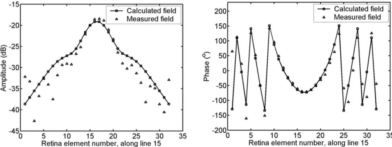
-Finally, a global complex calibration coefficient is obtained by using the data from a cylindrical reference object to fit with a known analytical solution. Here, a PVC circular cylinder whose diameter is 35 mm has been used. Figure 3 provides an example of calibrated results. While phase results show a very good agreement, further studies are currently conducted to reduce amplitude’s errors.
Figure 3: Comparison between calculated and measured scattered field of a 35 mm PVC cylinder with a complex correction of the measured field.
5 SIMULATIONS
In the following, an elliptical breast model, whose dimensions are 100 x 76 mm, is used. It contains a 15 mm diameter tumor and is surrounded by water (Figure 4). It is discretizised into 27 x 21 cells. The size of a cell is 2 /7. Reconstructions are performed from a set of 64x32 or 64x33 and thus are obtained after a few minutes on a Sun working station. The values of the complex permittivity used are those given in Table 1. Note that they come from a good compromise between measured values on existing phantoms materials and those found in the literature.
Materials r’ r” Breast tissue 35 5
Tumor 65 14
Skin 37 8
Water 77.3 8.66
Table 1: Complex permittivity used in the model [1,2,4,6].
Figure 4: The elliptical breast model. 5.1 Comparison between the planar camera and two circular scanners
In order investigate the planar geometry compared to the circular geometry with respect to topographic ability, a comparison with two other circular multi-view systems is presented (Figure 5). They differ from the repartition of the receiving antennas and from the nature, frequency and position of the incident wave.
Each system uses 64 views, one view consists of a set of M complex values of the scattered field at Rm (m=1,2 ….M) receivers positions. Each view changes with the transmitter’s position or plane wave
incidence, and is obtained by rotating the view axis represented by the dotted line in Figure 5. In the planar camera configuration (Figure 5a), a 2.45 GHz incident plane wave is considered. 32 receivers are located on a 22 cm straight measurement line, whose center is distant of 19.8 cm from the transmitter. In the two circular configurations, a 2.33 GHz cylindrical incident wave is used. 64 antennas on a circular array, whose diameter is 25 cm, can be operated in transmitting or receiving mode. When a given antenna T is transmitting, the others R one are used as receiving antennas. As shown in Figure 5, the R positions (33) are located on a half circle in the opposite side of the transmitter T (Figure 5b) (Broquetas, 1991), while 32 measurement positions located on the complete circle, are used in the configuration (Figure 5c) (approximately (Meaney, 2000)).
Figure 5: The 3 different multi-view configurations (a) Planar camera (b) Barcelona camera (c) Complete circular system.
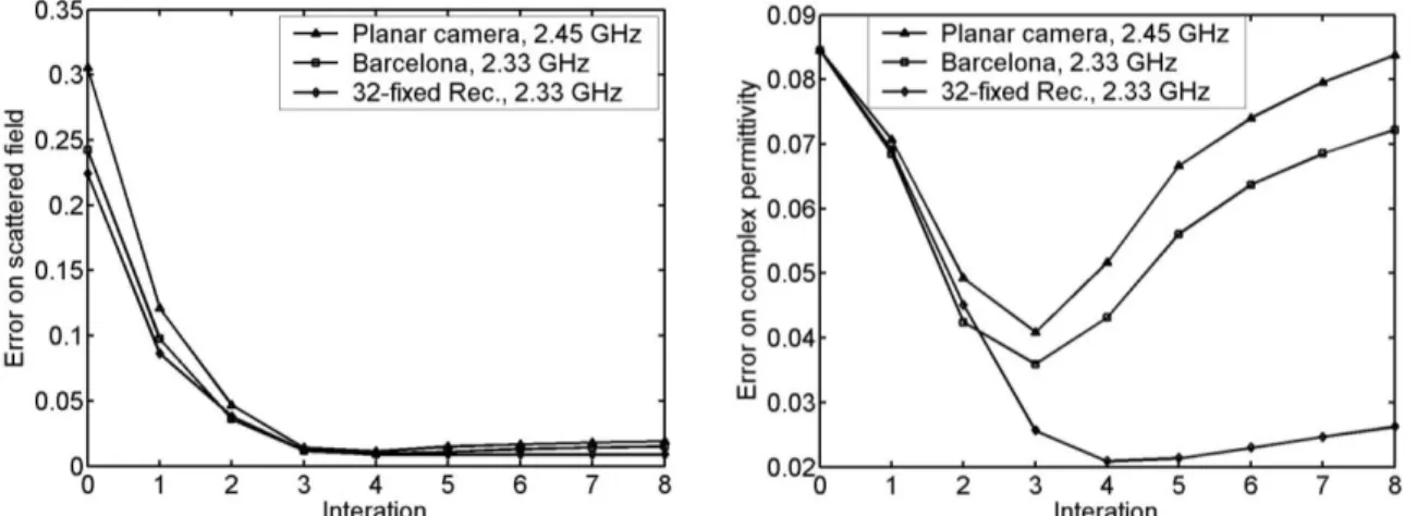
Figure 6 shows the results obtained at iteration 3 for the three different multi-view systems when a signal to noise ratio of 40 dB is considered. It appears that similar successful quantitative results are
obtained for the planar camera (Figure 6a) and for the Barcelona system (Figure 6b). Figure 7 shows the convergence of the algorithm, e.g. the relative mean square error on the scattered field and the one on the solution during the iterative process. As one can see, even if the complete circular system gives a slightly better result than the two other cases, satisfactory results are provided after a few iterations. Notice that the best result is obtained for every system at the same iteration (number 3) and for the lower error on the scattered field.
Figure 6: complex permittivity distribution (up real part, down imaginary part),
solution at iteration n°3 with different multi-view systems for a S/N = 40 dB: (a) 2.45GHz planar camera (b) 2.33GHz Barcelona camera (c) 2.33 GHz complete circular system (d) initial guess (e) exact solution.
Figure 7: Convergence scheme of the three different systems using simulated data with SNR 40 dB.
5.2 From multi-view to multi-incidence systems
Rotations are not suitable for breast tumor detection applications, and thus multi-incidence could be a better alternative than multi-view system. The question is to know if such a system is able to provide enough independent data. In this context two multi-incidence (instead multi-view) configurations have been considered. The use of the retina has been voluntary conserved and, only the emission part has been changed. The emitters are placed on a linear array (Figure 8a), for the first configuration and along an elliptical array (Figure 8b) for the second one. In each case 64 emitters are used, in order to get the same number of data as in the multi-view case.
Figure 9 shows the reconstructed images after 4 iterations for both alternative setups. Results for the planar camera have been added for comparison. As one can see, the tumor is detected even when a linear array is used for emission. The elliptical setup gives the opportunity to improve the image and seems to be a good alternative in the case of the object/antenna rotation is impossible.
Figure 8: Geometry of the two multi-incidences configurations (a) linear array (b) elliptical array.
Figure 9: complex permittivity distribution (up real part, down imaginary part), solution at iteration n°4 with different 2.45 GHz systems for a S/N = 40 dB : (a) multi-incidence linear array (b) multi-incidence elliptical array
(c) multi-view planar camera.
6. CONCLUSION
Compared to other existing systems, the major advantage of the microwave camera consists of its high data acquisition rate and its potential to perform rapid 3D full polarimetric data acquisition and related processing. It has been shown that its geometry allows obtaining 2D reconstructed images similar to those provided by more popular circular scanners already considered for breast cancer detection. Furthermore, an extension from multi-view to multi-incidence system seems to be a strong alternative when a rotation is impossible in the acquisition. Present efforts are focused on the construction of a high contrast phantom for breast tumor detection. Further work will be focused on phantom experiments with the planar camera to obtain quantitative images of experimental data using the presented calibration technique.
7. REFERENCES
Li D., Meaney P. M. and Paulsen K. D., (2003), Conformal Microwave Imaging for Breast Cancer Detection, IEEE Trans. on Microwave Theory and Techniques, 51, 1179-1186
Meaney P. M., Fanning M. W., Li D., Poplack S. P. and Paulsen K. D., (2000), A Clinical Prototype for Active Microwave Imaging of the Breast, IEEE Trans. Microwave Theory and Tech. 48, 1841-1853
Fear E. C., Li X. and Hagness S. C., (2002), Confocal Microwave Imaging for Breast Cancer Detection: Localization of Tumors in Three Dimensions, IEEE Trans. Biomed. Eng, 49, 812-822
Li X., Davis S. K., Hagness S. C., van der Weide D. W. and Van Veen B. D., (2004), Microwave Imaging via SpaceTime Beamforming: Experimental Investigation of Tumor Detection in Multilayer Breast Phantoms, IEEE Trans. on Microwave Theory and Techn., 52, 1856-1865
Bindu G., Lonappan A., Thomas V., Aanandan C. K., and Mathew K. T., (2006),” Active Microwave Imaging fo breast cancer detection”, Progress In Electromagnetics Research, PIER 58, 149-169 Miyakawa M., Ishida T. and Watanabe M., (2004), Imaging Capability of an Early Stage Breast Tumor by CP-MCT, Proceeding of the 26th Annual International Conference of the IEEE EMBS San Francisco, CA, USA
Joisel A. and Bolomey J. C., (2000), Rapid Microwave Imaging of Living Tissues, SPIE Symposium on Medical Imaging San Diego, CA, USA, February 12-18
Broquetas A., Romeu J., Rius J. M., Elias-Fuste A. R., Cardama A. and Jofre L., (1991) Cylindrical Geometry: A Further Step in Active Microwave Tomography, IEEE Trans. on Microwave Theory and Tech., 39, 836-844
Joachimowicz N., Pichot C. and Hugonin J. P., (1991), Inverse Scattering: An Iterative Numerical Method for Electromagnetic Imaging, IEEE Trans. on Antennas and Propagat., 39, 1742-1752
Bolomey, J. C.; Gardiol, F. E., (2001), Engineering Applications of the Modulated Scattered Technique, [Series: Artech House Antennas and Propagation Library], ISBN: 1580531474
Franchois A., Joisel A., Pichot C., and Bolomey J.C., (1998), Quantitative Microwave Imaging with a 2.45 GHz Planar Microwave Camera, IEEE Trans. on Med. Imag, 17, 550-561
Rius C., Pichot C., Jofre L., Bolomey J. C., Joachimowicz N., Broquetas A. and Ferrando M., (1992), Planar and Cylindrical Active Microwave Temperature Imaging: Numerical Simulations, IEEE Trans. on Med. Imag., 11, 457-469
Joachimowicz N., Mallorqui J.J., Bolomey J. Ch., and Broquetas A., (1998), Convergence and Stability Assessment of Newton-Kantorovich Reconstruction Algorithms for Microwave Tomography, IEEE Trans.MI., 17, 562-570
Roger A., (1981), Newton–Kantorovich algorithm applied to an electromagnetic inverse problem, IEEE Trans Antennas Propagat., 29, 232–238
Chew W. C. and Wang Y. M., (1990), Reconstruction of two-dimensional permittivity distribution using the distorted Born iterative method, IEEE Trans. Med. Imag., 9, 218–225.
Franza O., Joachimowicz N. and Bolomey J. Ch., (2002), SICS: A Sencor Interaction Compensation Scheme for Microwave Imaging, IEEE Trans. on Antennas and Propagat., 50, 211-216
Bolomey J. Ch., (1997), Modulated probe arrays for rapid antenna testing; principle and applications, Electronics/communications HF, 2, 35-46
Caorsi S., Gragnani G. L.,, and Pastorino M., (1993) Reconstruction of Dielectric Permittivity Distributions in Arbitrary 2-D Inhomogeneous Biological Bodies by a Multiview Microwave Numerical Method, IEEE Tans. Med. Imag., 12, 232-239
Azaro R., Caorsi S. and Pastorino M., (1998), A 3 GHz-microwave imaging system based on a modulated scattering technique and a modified Born approximation, Int. Journ. Imaging Syst. Technol
Souvorov A. E., Bulyshev A. E., Semenov S. Y., Svenson R. H., Nazarov A. G., Sizov Y. E., and Tatsis G. P., (1998), Microwave Tomography: A Two-Dimensional Newton Iterative Scheme, IEEE Trans. on Microwave Theory and Techn., 46, 1654-1659
Meaney P. M., Paulsen K. D. and Ryan T. P., (1995), Two-Dimensional Hybrid Element Image reconstruction for TM Illumination, IEEE Trans. on Antennas and Propagat, 43, 239–247