CORROSION CRACK GROWTH IN A BI-MATERIAL SYSTEM Andrey P. Jivkov and Per Ståhle
Solid Mechanics, Malmö University, SE-205 06 Malmö, Sweden andrey.jivkov@ts.mah.se
ABSTRACT
Bi-materials composed of thin layers ideally bonded to large substrates are considered. Cracks emerging from an almost flat surface and propagating through the bi-materials are studied. The cracks acquire realistic geometrical shapes, where the tips are integral parts of the crack surfaces. Crack propagation is related to surface evolution resulting from material loss due to corrosion. Controlling mechanism for the evolution is the rupture of a brittle passive film, which is frequently building-up along the surface. The evolution rate is a function of the degree of film damage caused by the surface straining. The model leads to a moving boundary formulation, for which a numerical solution is used. The mismatch of the material plastic properties is being varied in the study. The results show how cracks pass the interface. The growth rate variation close to the interface is studied. Typical surface evolution for a crack passing through a soft-hard material interface is presented. The resulting crack morphology of the model resembles what has been observed in reality. It is shown how the results can be used in designing bi-material systems to inhibit corrosion crack growth.
INTRODUCTION
Fracture behaviour at interfaces has to be considered in a number of engineering applications such as coatings, composites and welded structures. The choice of materials in such systems is crucial for structural reliability, because it may lead to an accelerated fatigue crack growth. Fracture perpendicular to interfaces between ideally bonded linear elastic materials has been studied in [1-5]. It has been shown that the singularity exponent characterizing the crack tip stress field is no longer equal to one-half when the crack tip is placed exactly at the interface. Hence, the classical Griffith-Irwin fracture criterion cannot be directly applied, because the local stress intensity factor either grows infinitely or vanishes when the crack approaches the interface. One remedy might be to use a crack propagation criterion based on non-linear processes such as the cohesive zone model suggested in [6-7]. Another approach, applicable to fatigue corrosion crack growth, was recently proposed in [8-9]. This approach does not relay on a fracture criterion, but on the process of material dissolution as crack forming and crack advancing mechanism. This leads to cracks with realistic geometrical shapes, where the tip is not represented by a singular point but is an integral part of the smooth crack surface. The influence of the elastic mismatch on the fatigue corrosion crack propagation in elastic-elastic bi-material systems has been investigated in [9].
In a large class of applications, however, the plasticity must be accounted for. For certain bi-material compositions, the elastic mismatch effect on the near-interface crack behaviour might still be of interest [10-11]. For others, e.g. steel-steel bi-material systems, the plastic mismatch is of primary importance as reported in the experimental works [12-13]. Analytical investigations of fracture perpendicular to plastically mismatched interfaces [14-16], together with [12-13], show that by a proper choice of materials partners fatigue crack propagation could be inhibited or even impeded. This can be applied to environmental fatigue crack
growth. The present work follows the approach presented in [9] to study the influence of the strength mismatch on the fatigue corrosion crack evolution. The cracks nucleate from irregularities on a solid surface and propagate across an interface between two materials of identical elastic characteristics and differing plastic properties.
MODEL AND SOLUTION
Consider a plane bi-material body, consisting of a large substrate and a thin layer (Fig. 1). An elliptically shaped flaw of depth D and width W = 10D is supposed existing on the layer surface. The characteristic dimension of the body is B = 104D. The layer thickness is fixed to L = 5 0D. The materials of the layer and the substrate are assumed elastic-perfectly plastic with the same elastic modulus, E = 206 GPa, and Poisson’s ratio, ν = 0.3, but different yield stresses, σy. Two cases of material partners have been studied: a soft layer with yield stress σy = 270 MPa on a hard substrate with yield stress σy = 5 40 MPa; and a hard layer with yield stress σy = 540 MPa on a soft substrate with yield stress σy = 270 MPa.
The layer surface, X1 = 0, is assumed in contact with a corrosive environment and covered by
a passive film, which is supposed brittle in tension and of negligible thickness. The film behaviour is characterized by a single parameter – the strain at rupture, chosen as εf = 0.001 in this work. In an unloaded state of the body, the film is overall intact and prevents any dissolution due to corrosion. Upon loading, the film deforms together with the bulk material up to possible rupture. In the places of film damage the corrosion process dissolves material and advances the surface in the normal direction. A thorough description of the surface deformation-film rupture process is given in [8]. The relative elongation of a differential surface arc element, defined as ε = (ds –dS) / ds, where dS and ds denote the arc lengths before and after a deformation, respectively, is accepted as a surface strain measure. Note that ε < 1, and the film is considered damaged at a point if ε > εf. The rate of surface advancement at a point, R, is assumed proportional to the degree of film damage and an electrochemical
X1 X2 B B B L X1 X2 L W E, ν, σy1 E, ν, σy2 D T1 = T2 = 0 U1 = 0 T2 = 0 U2 = -u(t) T1 = 0 U2 = u(t) T1 = 0
Figure 1. Schematic illustration of the model geometry.
dissolution rate, Rd, according to
(
f)
d
R
R= εθ ε −ε , (1)
where θ (x) = 1 if x > 0 and θ (x) = 0 otherwise. The rate, Rd, is generally depending on the solid-solution composition and is varying in time because of repassivation processes and changes in the electrochemical conditions. For the considered fatigue loading, Rd may be thought of as constant, yielding the maximum possible surface advance per cycle, ∆d = Rd Td, i.e. the advance during time Td that would be achieved for fully damaged passive film [9]. The body is considered to be in plane strain. The boundary conditions are shown in Fig.1, where the displacements u(t) are applied in cycles of rectangular shape with peak duration Td, and a period T > Td. The peak magnitude of the displacements is chosen to be εf B, which ensures a homogeneous strain field in a body without surface irregularities. This way, the presence of a flow of any depth, similar to the one introduced in Fig. 1, would be sufficient to create strain concentration rupturing the passive film in the flaw and starting the process of crack formation and growth.
The model stated above poses a moving boundary value problem, where each load cycle is viewed as a new boundary value problem. The geometry of the new problem is determined from the history of the evolving boundary. The equilibrium of the new problem defines the present evolution. The problem is solved numerically, using a finite element method solver [17] for the mechanical equilibrium and an in-house procedure for surface evolution tracking and geometry re-meshing. The residual stresses and plastic strains, obtained after a load cycle closing, have been neglected when defining the boundary value problem for the next cycle. RESULTS
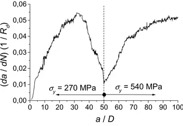
The results for crack advance per cycle (crack growth rate), da / dN, versus crack extension, a, are presented in Fig. 2 for the soft layer-hard substrate system and in Fig. 3 for the hard layer-soft substrate system, with N denoting number of cycles. In both figures the crack
0 10 20 30 40 50 60 70 80 90 100 0,00 0,01 0,02 0,03 0,04 0,05 0,06 σy = 540 MPa σy = 270 MPa (da / dN ) (1 / R d ) a / D
extension, a, is scaled with the depth of the crack initiating surface flaw, D, and the crack growth rate, da / dN, is scaled with the reciprocal of the electrochemical dissolution rate, Rd. The scatter in the growth rates has to do with the uncertainty of the numerical description of the surface.
Fig. 2 shows sudden drop of growth rate as soon as the plastic zone in front of the growing crack reaches the interface. Similarly, an increase is observed in Fig. 3, as expected. In both figures, when the interface is passed, there is a movement towards the results for the corresponding homogeneous cases, but the growth rates for these cases are not reached until the crack has advanced a distance of several plastic zone sizes into the substrate.
0 10 20 30 40 50 60 70 80 90 100 0,00 0,02 0,04 0,06 0,08 0,10 0,12 σy = 270 MPa σy = 540 MPa (d a / dN ) (1 / R d ) a / D
Figure 3. Crack growth rate evolution in the hard-soft system.
a
σ
y= 270 MPa
σ
y= 540 MPa
a
a
σ
y= 270 MPa
σ
y= 540 MPa
c
a
σ
y= 270 MPa
σ
y= 540 MPa
b
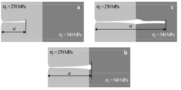
Figure 4. Evolving crack in a soft-hard bi-material system: (a) in the soft material; (b) at the interface; (c) in the hard material.
As an illustration, the morphology of the crack at three instances of its evolution in the soft-hard materials combination is shown in Fig. 4. In picture (a) the crack is shown growing in the softer layer and still far from the interface. Picture (b) shows the crack tip in the vicinity of the interface, and in picture (c) the crack is advancing in the harder substrate.
DISCUSSION
The moving boundary value problem, formulated in the model section, offers an advantageous method to study evolution of cracks with realistic geometries. The driving force for the evolution is the momentary strain controlled corrosion, removing material from the body. From a thermodynamic perspective the body is unstable at every instance. The corrosion rate constitutes an additional boundary condition, which compels the boundary to evolve, such that the redistributed stresses are maintained in an instantaneous equilibrium with the applied loads. The physical background of the model – the process of material dissolution – leads to a moving boundary value model for a continuous evolution of the boundary under constant applied load. When the passive film build-up is accounted for, an active loading becomes an essential prerequisite to maintain surface advancement. In this work the active loading is considered as a fatigue loading, but this is not an essential requirement for the results applicability. Qualitatively similar results would be achieved if the loads were increasing in steps of sufficient duration to let the repassivation process completely restore the passive film.
The observed behaviour of the crack as it penetrates the interface can be seen in Figs. 2 and 3. The transition is from the expected crack growth rate in the layer to the expected rate in the substrate. However, during the transition from a soft material to a hard one, the crack growth rate is decreasing to very low values as the interface is crossed. For a crack coming from a hard material to a soft one, a peak with high growth rates is observed.
The low crack growth rates observed at the interface of the soft-hard system are lower than the rate, that would be found in a homogeneous hard material and much lower than the rate in
a
b
Figure 5. Stress corrosion crack in a bi-material pressure vessel component: (a) interface region; (b) crack tip region. With the permission from Vattenfall, Sweden.
a homogeneous soft material. Experimental observations show that the crack tip may blunt and corrosive removal of material spreads out from the crack plane (Fig. 5). The effect on the crack growth rate is pronounced since apart from the direct rate reduction due to the arrival at the harder material the blunting of the crack tip reduce the strain concentration and, hence, also reduce the crack growth rate.
Blunting to some degree is observed in the simulations as shown in Fig. 4. Neglected residual strains may increase this effect. Residual strains are larger in a soft material than in a hard material. It is known from non-linear fracture mechanics that the residual strains reduce the strain concentration at the crack tip [18]. A speculative argument may be that the larger residual strains obtained during cycling in the softer material inhibit crack growth when the plastic zone is partly inside the harder material.
Fatigue cracks approaching an interface between a soft and a hard material where the crack initially is in the softer material are observed to arrest in front of the interface. In some cases the crack continues growing in a direction parallel with the interface [12]. This phenomenon is controlled by the threshold for fatigue crack growth. A similar behaviour is anticipated for the corrosion crack. However, the present analysis is limited to a linear relationship between strain and crack advance during a load cycle. The lack of a strain singularity and accordingly the possibility that all plastic deformation vanish for small load suggest a strong sensitivity to threshold strain, e.g. for materials insensitive to elastic straining.
REFERENCES
[1] A.R. Zak and M.L. Williams, J. Appl. Mech.-Trans. ASME, vol. 30, pp. 142-143, 1963.
[2] F. Erdogan and V. Biricikoglu, Int. J. Eng. Sci., vol. 11, pp. 745-766, 1973.
[3] M.C. Lu and F. Erdogan, Eng. Fract. Mech., vol. 18, pp. 491-506 and pp. 507-528, 1983.
[4] M.Y. He and J.W. Hutchinson, Int. J. Solids Struct., vol. 25, pp. 1053-1067, 1989. [5] A. Romeo and R. Ballarini, J. Appl. Mech.-Trans. ASME, vol. 62, pp. 614-619, 1995. [6] A. Romeo and R. Ballarini, Int. J. Solids Struct., vol. 34, pp. 1307-1326, 1997. [7] D. Wäppling, J. Gunnars and P. Ståhle, Int. J. Fract., vol. 89, pp. 223-243, 1998. [8] A.P. Jivkov and P. Ståhle, Eng. Fract. Mech., vol. 69, pp. 2095-2111, 2002.
[9] A.P. Jivkov, Research Report MUMAT2002:6, Malmö University, 2002. (submitted) [10] A. Romeo and R. Ballarini, Int. J. Fract., vol. 65, pp. 183-196, 1994.
[11] P. Delfin, J. Gunnars and P. Ståhle, Fatigue Fract. Engng. Mater. Struct., vol. 18, pp. 1201-1212, 1995.
[12] S. Suresh, Y. Sugimura and E.K. Tschegg, Scripta Metal. Mater., vol. 27, pp. 1189-1194, 1992.
[13] Y. Sugimura, L. Grondin and S. Suresh, Scripta Metal. Mater., vol. 33, pp. 2007-2012, 1995.
[14] A.S. Kim, S. Suresh and C.F. Shih, Int. J. Solids Struct., vol. 34, pp. 3415-3432, 1997. [15] R. Pippan and F.O. Riemelmoser, Comput. Mater. Sci., vol. 13, pp. 108-116, 1998. [16] A.S. Kim, J. Besson and A. Pineau, Int. J. Solids Struct., vol. 36, pp. 1845-1864, 1999. [17] ABAQUS User’s Manual, Version 6.3, Hibbitt, Karlsson & Sorensen Inc., 2002. [18] W.J. Drugan, J. R. Rice, and T-L. Sham, J. Mech. Phys. Solids, vol. 30, pp. 447-473, 1982.