Use of Converters for Feeding of AC Railways for All
Frequencies
Lars Abrahamssona, Thorsten Sch¨utteb, Stefan ¨Ostlundc
aSchool of Electrical Engineering, Electric Power Systems, KTH Royal Institute of Technology,
Teknikringen 33, SE-100 44 Stockholm, Sweden
bAtkins Sverige AB, Kopparbergsv¨agen 8, SE-722 13 V¨aster˚as, Sweden
cSchool of Electrical Engineering, Electrical Energy Conversion, KTH Royal Institute of
Technology, Teknikringen 33, SE-100 44 Stockholm, Sweden
Abstract
Railways are the most energy-efficient land-based mode of transport, and electrification is the most energy-efficient way to power the trains. There are many existing solutions to supply the trains with electricity. Regardless of which particular technology is chosen, it is beneficial to interconnect the public power grids to grids supplying power to the railways. This paper shows that the most effi-cient, flexible, and gentle-for-the-public-grid way of doing that is through power-electronics-based power converters. Converters offer great benefits regardless of whether the overhead contact lines are of DC-type or AC type, and regardless of the AC grid frequency.
This paper presents neither new theory nor new experimental results. Based on already available information, this paper presents logical arguments leading to this conclusion from collected facts. Over time what used to be advanced and high-cost equipment earlier can nowadays be purchased at reasonable cost. It is obvious that for most electrically-fed railways, the use of modern power con-verters is attractive. Where the individual trains are high consumers of energy, the railway gradients are substantial, and the public grids feeding the railway are weak, the use of converters would be technically desirable, if not necessary for electrification.
It is expected that more high-speed railways will be built, and more existing railways will be electrified in the foreseeable future. This paper could provide some insights to infrastructure owners and decision makers in railway administra-tions about value addiadministra-tions that converter-fed electric railways would provide. Keywords: railway power supply systems, converters
1. Introduction
This paper presents and analyzes various ways of feeding electric power to railways. The paper also aims to point out the many benefits of using converters for feeding electric railways instead of feeding electricity directly from substation transformers. Most discussions focus on and consider only public-grid-frequency (50 Hz or 60 Hz) railway power supply system grids, since those are the only railways that can be fed from direct substation transformers. Moreover, that is presently the most common feeding technology for electric railways. In this paper, while using the expression ”railway power supply system” we refer to the entire power supply system feeding the trains of the railway including the electric grid managed by the railway administrator.
The other main feeding systems for railways are:
1. DC railways, the oldest railway feeding technology, totally dominating sub-ways, trolleys, light rail, trams, and the like; and,
2. Low-frequency (1623 Hz in Northwestern and Central Europe and 25 Hz in Northeast America) AC railways, the pre-war only possible way of feeding largely power-consuming AC locomotives.
A railway power supply system (RPSS) differs from a classic public power grid in the following respects:
• the loads vary heavily in – time,
– location, – size,
– and power factor.
• Substantial voltage drops are more likely to occur, but on the other hand, the loads much less sensitive to substantial voltage drops than many public-grid loads. Tractive forces and active power consumptions of trains are controlled down for low voltages.
Email addresses: lars.abrahamsson@ee.kth.se(Lars Abrahamsson),
Thorsten.Schutte@atkinsglobal.com(Thorsten Sch¨utte), stefan.ostlund@ee.kth.se (Stefan ¨Ostlund)
• The power sources are normally rated in the same orders of magnitude as the loads.
The subsequent sections in the paper are organized as follows:
Section 2 contains a briefing of railway electric power supply systems in general, their different properties, and more details of how to particularly feed them. In this section, the symmetric loading of converters contra the unsymmetri-cal loading of direct transformers is also discussed. Asymmetries force the catenaries to be sectioned.
Section 3 discusses the drawbacks of catenary sectioning. Sectioning is not re-quired when using static converters.
Section 4 discusses the benefits gained from controllability of railway converters. Section 5 lists other issues in this comparative review.
Section 6 contains a brief discussion of low-frequency railway grids.
Section 7 presents the conclusions drawn from the information and arguments gathered, followed by a discussion and a bullet-list summary.
Section 8 contains the acknowledgements.
Economical and technical benefits are treated as a whole and purposely not sepa-rated in the text.
Converter usage opportunities in China are discussed in (Behmann and Rieck-hoff, 2011b). A more general and compact presentation of converter usage op-portunities can be found in (Sch¨utte and Behmann, 2011). More detailed and case-specific presentation can be found in (Behmann and Sch¨utte, 2012d,e,c,b,a). In this paper, we argue for the use of converters – not only in existing low-frequency railways, or new investments in low-low-frequency systems, but also for using converters in railways with the same frequency as the public grid. Possi-ble disadvantages with converter technology are also discussed. A paper with a slightly different target group, but with similar focus as this paper is (Behmann and Rieckhoff, 2011a).
In this paper, at places where 50 Hz is mentioned, it could be replaced by 60 Hz for countries where 60 Hz is the public grid frequency and should be kept in mind by the reader.
2. Important Properties of Railway Power Supply Systems
In Section 2.1 a basic, but sufficiently detailed description of how electrified railways can be fed with electricity, is given. The three main types of electric railway feeding systems are described, along with their pros and cons. Converters are introduced and described in Section 2.2.
With this introduction, it should be possible for the uninitiated reader to follow the remainder of this article.
2.1. Briefing about Railway Power Supply Systems
Railways are the most energy-efficient land-based means of transport. The most energy-efficient way of powering them is through electric motors. The most energy-efficient way of delivering this power is through an electric power sup-ply system alongside the railway tracks. These systems can be made even more efficient by the use of converters.
RPSS:s (Railway Power Supply Systems) are, for practical reasons, either sin-gle phase AC or DC systems. The AC systems may either be operated at the same frequency as the public power grid or at a different frequency, normally a lower frequency. There are several different standards for the contact line voltages for both AC and DC railway systems. Electricity is delivered to the trains in different ways, often through an overhead contact line normally called the catenary.
In fact the catenary is a geometrical shape. In mathematics, the catenary is the curve that is theoretically assumed by a perfectly flexible and inextensible cord of uniform density and cross section hanging freely from two fixed points. The physical catenary goes somewhat above the actual overhead contact line. It is however normal to denote the entire system of conductors hanging from the poles alongside the railway line as the catenary system. For subways, it is common with conductors on ground level, similar to the third-rail system common mainly in Great Britain.
DC railway power supplies and AC railway power supplies with different fre-quency have similar topologies, that is electric power has to be converted by power converters to be able to flow between the public grid and the railway grid. Doubly fed RPSS sections are connected as in Figure 1. The abbreviation CE stands for ”connecting equipment”, i.e. a general term for converters, rectifiers, or substation transformers. The boxes labeled Z denote power system impedances, represent-ing the impedances of catenary, rail, and possible feeder lines. The down-pointrepresent-ing arrows labeled S represent the apparent power consumed by the two sets of motor-ing trains available in the power system section. The values of the apparent power
Z Z1 Z2 Z3 Z S1 S2 1 phase CE 3 phase 1 phase CE 3 phase Previous power system
section This power system section
Next power system section Public Grid Railway Grid
Figure 1: A section of the railway power supply system, illustrated as an electric circuit.
loads change with train model, acceleration, speed, and position of the trains, as well as with the voltage levels of the catenary line where the trains are located. The values of the impedances, Z, change with time as the trains move.
2.1.1. Feeding of AC Railways, Symmetries and Asymmetries of the public Grid AC railway grids with public frequency often just have transformers instead of converters, using two of the public grid’s three phases. With that solution, in order not to cause excessive asymmetrical loading, the public-grid phases, are altered for each consecutive transformer station. Therefore, because of the 120◦ phase angle difference, in contrast to the configuration of Figure 1, the public-grid-frequency railway with transformers as CE is never fed from more than one CE at once. For such a public-frequency railway system, the contact line would have been sectioned where Z2is located in Figure 1.
In the simplest case, the RPSS constitutes a load between a pair of the three phases in the public grid, c.f. Figure 4. When using e.g. Scott transformers, all three phases are loaded, and the asymmetry is reduced somewhat, c.f. Figure 2. On the other hand, when feeding railways via converters, the electricity is collected symmetrically from the public grid.
On the left-hand side in Figure 2, the transformer connecting three-phase grid and single-phase grid is described in a simplified form. On the right-hand side
of Figure 2, specially designed transformer types to reduce load imbalances are described, e.g. Leblanc, Scott, V/V, Y/∆, Y/∆∆, and Y/V. Based on Figure 3 in (Behmann, 2000).
In the parts of the world where the population density is high, the public power systems are normally strong as well, and the loads of the railway power supplying substations can more or less be neglected in relation to the amounts of installed capacity and other fluctuating loads. In most parts of the world, however, the bene-fits of using converter stations in the railway power supply become more apparent. The weaker the supplying public grid, the more vulnerable it is to asymmetrical loads.
Figure 2: Three-phase and single-phase HV grid load. c Uwe Behmann Unsymmetrical load and unwanted reactive power result in electricity bill sur-charges. Using converters such surcharges can be avoided.
2.1.2. Feeding of DC Railways
DC railways normally operate on comparatively low voltages. The usage of lower voltages is related to safety and what used to be techno-economic con-straints. The safety issue is that breakers for high-voltage DC needed for protect-ing passengers and engineers are more complicated and expensive to produce and design. The techno-economic constraint was that there were no reliable and eco-nomical ways of transforming between different DC voltage levels. With mod-ern power converters that is no longer a problem, and DC railways could now for example be fed with AT-like systems (Ladoux et al., 2006), or with HVDC transmission lines (Abrahamsson et al., 2012a; Vial et al., 2010b; Abrahamsson et al., 2012b). Due to the low voltage of today’s DC-railway solutions, these sys-tems are best suited for low-load trains like light rail, trams, subways, trolleys, and the like. The main reasons for the popularity of DC-railways are similar to those for converter-fed AC-railways, and the fact that DC equipment is normally
cheaper than special tailor-made components for 1623 Hz and 25 Hz systems. How to migrate DC railways to converter-fed AC railways is discussed in (Behmann and Sch¨utte, 2012d), whereas HVDC-fed railways are discussed in (Abrahams-son et al., 2012a).
A more thorough overview of railway power supplies can be found in (Good-man, 2008).
2.1.3. How to Dimension the Railway Power Supply System
The CEs (”CE” in Figure 1) of a railway power supply system, may it be trans-formers, frequency converters, or rectifiers, normally have some kind of voltage regulation on their railway side terminals. Even if there is no such regulation, as for example when the CEs are transformers, the connection to a comparatively strong grid will result in higher voltage levels closer to the connection point. Therefore if each pair of CEs are located close to each other, the voltage drops across the contact line will be smaller for a given load.
There are two main ways of operating the CE, of which the second way can be subdivided into two.
1. The first way is to only use the CE as power sources, one-directional power flows from public grid to railway. This is sometimes chosen on account of its lower cost; pure rectifiers are, for example cheaper than rectifiers and inverters combined. But it can also be due to the unwillingness of public-grid-owners to accept regenerative power from trains to be fed back to the public grid. Regeneration in particular is discussed in Section 3.3.
2. The second way is that the CEs allow a free flow of power back and forth depending on where there is a surplus of power for the moment, and where there is a demand. Within the second way, there are two main type of RPSS operation.
• Either it is just a flexible industrial grid, that when, on occasions, there is a surplus of regenerated power, that surplus is exported. But both on short-term and medium-term time scales, there is a net import of electric energy from the public grid to the RPSS. Regeneration in par-ticular is discussed in Section 3.3, whereas the control of converter power flows in general is discussed in Section 4.2.
• Or that the RPSS grid owner has, and operates his/her own power plants. These are then operated, not only to feed the trains with power in an efficient way (Blacutt, 2009), but also to export power to the pub-lic grid, when demand and energy prices are higher on the pubpub-lic-grid-
public-grid-sides of the converters (Weiland, 2009). More of direct generation is discussed in Section 2.2.
Trains are slowed down for large voltage drops, i.e. their maximum attainable tractive forces are reduced (Danielsen et al., 2006). Energy and power losses also increase for large voltage drops if the power consumption remains constant. Voltage drops can be counterbalanced either by reducing the impedances between the CEs or by active voltage control. For active voltage control, power converters are especially suitable.
The impedance between the CEs of the RPSS as a whole can be reduced • by reducing the impedance of the catenary system, which in turn can be
done
– by adding additional conductors, like e.g. additional feeders, return conductors, etc.
– by increasing the conductor areas
– or by using technology that doubles the catenary voltage, without pan-tograph and train transformers taking any notice. That technology is called AT (auto transformer) for AC railways. AT catenary systems (Hill, 1994; B¨ulund et al., 2004; Pilo et al., 2003; Glover et al., 1984) are sometimes also called dual systems or 2·V L kV systems (where V L denotes the voltage level) (Pilo et al., 2003). There also exist power-electronics based solutions with dual voltage contact line systems for DC railways (Ladoux et al., 2006).
• By distributing the CE denser.
• Or by connecting a high voltage transmission line in parallel to the cate-nary system. This is easier to implement if using converters as CE. Parallel transmission lines are discussed in a historical context in Section 2.2. In the above bullet list, the dual-voltage techniques of AT catenaries were dis-cussed. For RPSS dimensioning, it is also worth mentioning the so-called BT (booster transformers) based catenary systems (Hill, 1994; B¨ulund et al., 2004; Abrahamsson, 2008). Booster transformers are used to absorb the return cur-rents back to the CE through catenary return feeders instead of absorbing them in the ground or in the rails. Corresponding technical solutions made of actively controlled power-electronics-based components have been suggested for both AT
railways (Tuttas, 1999, 2000) and DC railways (Fotouhi et al., 2009). Depending on ground impedance and the AC frequency used, the need of using BT catenary systems varies geographically.
2.2. Converters, used for feeding Railway Power Systems
As implicitly explained in Section 2.1, a converter is a device that changes forms of electricity. Typical examples from the railway field are: converting three-phase AC to single-three-phase AC of the same frequency, converting three-three-phase AC to single-phase AC of different frequencies, three-phase AC to DC, and DC at one voltage level to DC at another voltage level. Converters can be designed in many ways, mainly as electromechanical (rotary), where a motor and a generator are connected to the same shaft, or as power-electronics-based (static) ones. Modern converters use power electronics, and are thereby more flexible and controllable. This paper advocates the usage of modern converters. Electromechanical convert-ers, have most of the benefits that modern ones have, but not all of them.
In converters, as in most electrical devices, there are losses. However, the main idea is that the input and output of active power are the same. Active power is something physical, whereas reactive power is a measure of phase-shifts be-tween current and voltage in an AC system. Reactive power can be used to raise or lower voltage levels, and thereby e.g. decrease losses or increase train traffic performance.
In the dawn of railway electrification, converters were introduced because there were no other options – now when more and more railways are being built and being electrified, also in rural parts of the world, and the power demands of the trains are increasing – the introduction of converter-fed railways will not be a must, but an opportunity.
Back in 1910, a need for electrification of long distance electric railways in Central and Northern Europe (Hill, 1994) and on the east coast of North America (Hill, 1994) arose. This need was natural since electrically fed trains are less pol-lutant and more energy-efficient than diesel-trains and coal-steam trains. Diesel trains did not still exist at that time, neither diesel-hydraulic, nor diesel-electric, nor diesel-mechanical. Long-distance railways were to a great extent located in rural areas; going through vast areas far from major railway hubs and far from the nation-spanning or other high-voltage transmission lines of the public grid. At the time, powerful propulsion engines were available only as motors requir-ing special low frequencies. As a consequence, railways developed srequir-ingle-phase low frequency (1623 Hz in Central and Northern Europe, and 25 Hz in Northern
America) railway power supply grids. These were often supplied from railway-grid-connected power-plants producing electric power directly at the frequency of the railway grid without any conversion stage. The electric power was transmitted from power plants out to the catenaries along the railway tracks via twin-pole HV lines and single phase transformation into the single-pole catenary networks. Till today, a large proportion of the power consumed in the low frequency railways of the world is produced directly into the railway power supply grids at the lower frequency (Weiland, 2009; Blacutt et al., 2010).
Later on couplings between three-phase AC 50 Hz and 1623 Hz double-phase AC high voltage or single-phase AC catenary were implemented. Initially it was done using rotary converters and since the 1970’s using static converters also. Germany implemented static converters as late as the mid 1990’s (Weiland, 2009), in a controllable centralized grid.
In some parts of the world, railway electrification started not before the 1950s. Up to then, the three-phase AC 50 Hz (three-phase AC 60 Hz in some parts of the world) public grids had been expanded, extended, and were widely available for traction feeding purposes. Due to the fact that in the postwar era financial resources were often scarce and the fact that rectifiers, suited for use in traction units, were already under development, the single-phase catenary of railways was connected to the three-phase national grid using transformers. Today in USA, 60 Hz single-fed railways coexist with 25 Hz double-fed railways, like 50 Hz railways and 1623Hz railways coexist in Europe. Japan used DC railways, and the remaining 60 Hz world probably did not electrify their railways until the 1950’s.
A historical review of the development of and types of railway power supply systems can be found in (Gladigau, 1987).
3. Sectioning of catenaries – an obstacle for energy efficient operation In public-grid-frequency railway power supply systems, using transformer substations as CEs, the catenary has to be sectioned. The main issue is that using the same phase all the time as the ”railway phase” in the public grid creates a sig-nificantly unbalanced load for the public grid owner, not only locally – which in inevitable with this kind of CE – but also on a global scale. Therefore, the phases utilized by the RPSS have to be altered periodically. For a thorough discussion about asymmetries in public grids caused by railway traffic. Since each phase has a phase-shift of 120◦, different phases cannot be connected directly, and thus the catenaries connected to different phases of the public grid have to be separated
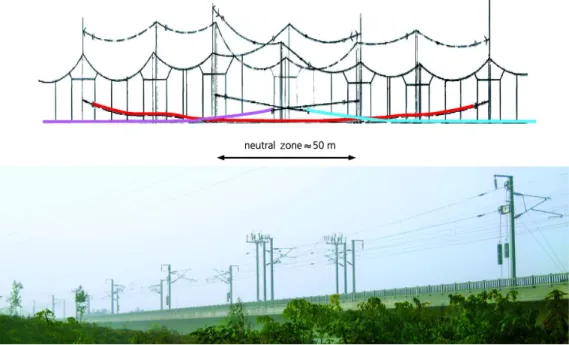
Figure 3: A phase-separated catenary. Picture originates from (Zimmert and Solka, 2009)
from each other. Feeding sections of the the catenary network, hence, are sup-plied with electricity from different phases of the public-grid. The various phases of the catenary require the catenary-sections to be electrically isolated from each other by means of phase separators, c.f. Figure 3. This is illustrated schemati-cally in Figure 4, where the transformers in reality often are of the types shown in Figure 2. Sectioning is also visualized in Figure 5, marked as ”4” in the figure.
In Figure 3, in the upper picture, the red line denotes the neutral section, whereas the purple and cyan colored lines denote two different conducting phases. The lower picture in Figure 3 illustrates the Wuhan–Guangzhou line.
The asymmetric load problem is not a merely a theoretical situation that arises once in a while for very weak grids. This happens today in, for example, both Taiwan (Hsi and Chen, 2001) and mainland China (Wan et al., 2010). It is shown that if trying to completely balance a single phase load on a three-phase grid, a large amount of compensating reactive power will be needed (Wan et al., 2010). Balancing asymmetries demands the use of reactive power. Investments in power electronics equipment will be so large then, that the marginal cost for actually investing in power converters between three-phase AC and single-phase AC can
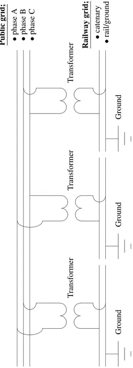
Ground Ground Ground Public grid; • phase A • phase B • phase C Railway grid; • catenary • rail/ground T ransformer T ransformer T ransformer
Figure 4: A simplified illustration of how the three-phase grid commonly feeds the railway when using substation transformers
be expected to be small. This small marginal cost is well justified by other benefits of using converters instead of power transformers.
To summarize, separation is needed for two reasons:
1. Big single-phase/unbalanced loads are not good for the public grid. Thus, these loads are taken from alternating phases in the public grid, c.f. Figure 4. 2. Since the phases feeding the RPSS are altered, the lines cannot be connected
because of the phase-separation.
In the following subsections, the drawbacks of sectioned railway power systems and the benefits with interconnected railway power systems are discussed.
3.1. Increased number of feasible connection points between public and railway grids
Doubly fed railway power sections imply reduced loads on each CE for a given traffic. That in turn, allows traction system feeding not only from high voltage public grids, but also from public grids with comparatively low voltage levels, even from medium voltage grids, c.f. Figure 5. Converter usage makes electrical traction with single-phase 25 kV an alternative also for regions or countries with limited short-circuit power of the public three-phase AC grids (Sch¨utte, 2011). In present-day Norway, the RPSS is, at locations, fed from the public 22 kV grid. If a lower public-grid voltage is sufficient for connection to the railway grid, prices for switch gear and primary main transformers will fall dramatically, compared to connections using higher public-grid voltage levels.
In Figure 5, different feeding schemes from public grid down to catenary for catenary systems of public-frequency type are illustrated. The upper circuit dia-gram illustrates a conventional (i.e. a comparatively simple) feeding system. The mid circuit diagram illustrates a dual-voltage (Pilo et al., 2003) system. The lower circuit diagram illustrates a system fed through converters. Based on Figure 7 in (Behmann, 2000).
Thus being allowed to connect to lower-voltage nodes in the public grid, in-vestment costs per CE unit may be reduced. It is easier to find a nearby connec-tion point. Supply lines will be shorter, and the sizes of their armatures, masts and foundations smaller. However, larger numbers may be needed thereby neces-sitating proper investment analysis to make the optimal choices. Using converters does increase the number feasible of choices, and as a consequence, the total costs are likely to be lower.
Connecting to the lower voltage may also result in a slight increase of public grid losses; generally small enough to be acceptable. The increased losses could also be a part of a future trade-off investment study.
Additionally, when using converters, thanks to controllability of power flows, if the supplying public grid is weak, one can choose to have many low rating con-verters densely distributed, rather than having a few big ones. When one converter saturates due to a large load, its neighboring units have to contribute. Converters can also be controlled such that even if the allowed active power flow saturates, they can use their reactive power to compensate for voltage drops along the line, a converter connected to a weak grid might act as a reactive compensator combined with a moderately sized power source. The power factors can also be adjusted on the public-grid side in order to cause as small harm as possible.
Electrical traction with single-phase 25 kV becomes an alternative also for regions or countries where up to now, only retaining of diesel traction or in-stalling of more expensive DC-feeding systems is feasible due to the limited short-circuit power of the three-phase AC grids. Detailed simulation results com-paring converter-fed railways with transformer-substation-fed ones are presented in (Behmann and Sch¨utte, 2012d). The topography in many regions where the alignment includes very long sections with up- and down-gradients, resulting in extra need for tractive power, having good capacity in the railway power supply is of importance.
Countries with a high proportion of heavy freight trains on long distances e.g. the US and Canada would have an extra gain by using converters when elec-trifying their main railway lines. Besides the fact that heavy freight trains need huge amounts of tractive power, they also pass through long distances in rural areas where not only the population density is sparse, but also so is the public distribution grid feeding.
3.2. Smoother public grid load fluctuations
Voltages fluctuate less in the public grid using power converters instead of substation transformers. This is mainly because of the interconnection of neigh-boring power sections which is not possible in classical transformer substation feeding. The transformer loads act as step-functions with respect to time when a fully motoring train suddenly connects to a new power section. This is not the case when using two-sided interconnected catenaries and converters. Then the train gradually approaches from far, with an all-the-time-increasing influence on the converter ahead of it. Similarly, when passing the converter, the load never disappears completely, it just slowly decreases as the distance increases to the
converter left behind, and increases to the converter being approached. In such a situation, it is also easier for control mechanisms to gradually cope with the fluctuations.
Traction units, when passing such neutral sections, have to cut off power, a measure which has to be controlled and monitored automatically in case of high performance railway lines.
3.3. Regeneration
Many railway power supply system administrators are confronted with a strong verdict by operators of the public grids against feeding back regenerative braking power into the grid. From the power suppliers’ perspective this electric power would flow into their grid without their control and randomly in terms of place and time.
Direct transformers are passive, i.e. non-controllable electrical elements. It is therefore physically unavoidable that this electro-magnetic link conveys regener-ated braking power into the public grid, once the voltage or impedance situation imposes such transfer. If such transfer is not allowed, this implies a ban on regen-erative braking.
A technical solution to this, while waiting for a better acceptance by the power industry of distributed generation, will be to use static converters in traction sub-stations. Since, in contrast to transformer substations converters provide no-load phase-synchronized voltages, the catenaries can be allowed to be linked together all along the railway line.
In case the catenaries are linked together, energy can be spread in both di-rections and according to the voltage limitations even beyond the bus bars in the neighboring converter stations. As a consequence, the probability of the energy being utilized by another traction unit rises sharply and at the same time the corre-sponding energy demand from the public grid is reduced. This is the core energy saving benefit of using converters.
Regenerated braking energy can be distributed over longer distances when the catenaries are interlinked. If the traffic is dense, the regenerated power will be delivered to an accelerating train not too far away from the train braking regener-atively. If the traffic is sparse, the regenerated power will be either used by a train far away, or fed back to the public grid, if the public grid owners allow energy to be fed back from the RPSS. If there are no accelerating trains at all on the inter-linked catenary section, and no feedback is allowed at any converter station, the over-voltage protection in the regenerative brakes on the braking train will force the train into pure mechanical braking.
In regions where the alignment includes very long sections with up- and down-gradients, the power consumption (and possible regeneration) will also typically be higher.
3.4. Robustness, Redundancy & Protection
Double-sided feeding reduces amperage and train-to-feeder impedance, and introduces voltage control on both sides. That leads to reduced operational volt-age drops, so that the spacing of CEs may be increased and/or dual-voltvolt-age sys-tems with auto transformers (AT) may become obsolete, c.f. Figure 5. In line with reducing amperage, electromagnetic interference of line-side equipment and other installations is decreasing, which had otherwise made AT or BT systems necessary. The term dual-voltage system used in Figure 5, means in the case of AC railways AT systems (Hill, 1994; B¨ulund et al., 2004; Pilo et al., 2003; Glover et al., 1984). In the case of DC catenaries, dual-voltage systems also exist (Ladoux et al., 2006) which are solutions based on power-electronics.
In Figure 5:
1. denotes a public three-phase AC 220 kV line;
2. denotes a traction power substation with specially designed transformers, c.f. Figure 2;
3. denotes the single-phase catenary system;
4. denotes the phase separation sections, c.f. Figure 3;
5. denotes the return conductor system – including the rail, the ground, and possible dedicated overhead return conductors;
6. denotes power substation transformers combined with AT transformers, one for each feeding direction, and AT feeding;
7. denotes the negative feeder of a double-voltage system; 8. denotes AT stations;
9. denotes a public three-phase AC 110 kV line.
In the sketch, it is pointed out implicitly, by having 9 (i.e. a public three-phase AC 110 kV line) when using converters, and 1 (i.e. a public three-phase AC 220 kV line) when using power transformers, that the railway power system can be fed from a weaker supplying public grid in the former case.
At the same time, when using converters, the amperage is limited to the rated current value even at short-circuits. The disadvantage is however that with a too simple catenary network over-current protection, it will no longer be possible for the system to distinguish between short-circuits and, for the relay protection sys-tem, too large a power consumption. This simple over-current protection can
Figure 5: Railway feeding schemes from public feeding grid down to catenary. c Uwe Behmann
however, be replaced with multi-stage distance protection. For some new types of converters an overload large enough for short circuit detection is permitted, (Halfmann and Recker, 2011).
3.5. Reduced investment needs and operation cost changes
The investments for neutral sections and the operational costs linked to them are avoided when interlinking the catenaries. Major investments are saved in case double-sided feeding eliminates the need for AT-equipment along the line. Lower interference levels will significantly reduce the costs of related protective mea-sures.
In the case of double-sided feeding, the load peaks for each individual CE and thus charges for power demand will decrease as the public grid connection fees are strongly correlated to the peak load levels of the railway. Given that the regen-erated braking energy is utilized in the RPSS, the charges for energy consumption will be reduced. Additionally, transmission losses are mitigated when feeding the catenaries from two sides.
In single-fed railway power supply BT catenary systems, all current consumed along the catenary segment passes the BT closest to the feeding sub-station. When feeding catenary segments from two directions, the amount of current flowing through the first BTs, at each feeding point, will be reduced depending on the locations of the loads. The long-term average currents through the BTs will there-fore be about halved, when using converters and feeding the railway from two directions. For a given traffic, either the BTs average lifetimes will be extended compared to using single-fed catenaries, or the RPSS grid operator may choose to use BTs with lower rated capacities, when using converters and doubly-feeding the RPSS.
As a consequence of reduced cost for many locations of converter installations, the spacing between CEs can be shortened if so desired. With shorter CE distances and appropriate voltage control, in some cases usage of the AT system will not be needed (Behmann and Sch¨utte, 2012d). If the traffic is very dense or heavy however, both strong grids and dense CE distributions will be a necessity. The optimal spacing of CEs, considering the voltage drops in the catenaries are studied in (Abrahamsson and S¨oder, 2009), where also the trade-off between impedances, traffic, and densely distributed CEs have been studied.
Finally, expenses for repair of catenary damages caused by short-circuit cur-rents are no longer incurred when changing from a transformer-fed RPSS to a converter-fed one.
4. Controllability 4.1. General
Static converters can actively control their active power flows, the reactive power, and the voltage levels and voltage angles on the catenary side. Therefore, the railway power system operator can also use the railway power system as a smart grid and trade power with the public grid owners (Vogel et al., 1997). The German railway power supply system for example is fully capable of doing that (Weiland, 2009). Moreover, the converters can be controlled to actively reduce the voltage drops and losses on the catenaries.
4.2. Power control
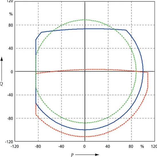
With the full controllability of converters, the energy flow between the national grid and the railway grid can thus be actively controlled and in accordance with current regulations feeding back can be blocked totally. The flow of electric power is adjustable within the limits of their performance specifications. This includes bidirectional feeding of active and reactive power. If, in the example shown in Figure 6 the active power limitation line is adjusted from -85 % to 0 %, any trans-fer of energy into the public grid is prevented (left-hand-side of the figure). This might be needed when connecting to grids, where the owners dislike distributed generation.
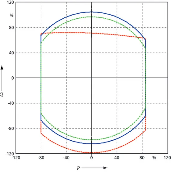
In Figures 6 and 7, the red lines illustrate the feasible apparent power areas for maximal network voltage, whereas the blue lines illustrate the feasible appar-ent power areas for rated network voltage, and the green lines for the minimum network voltage. Figure 6 illustrates the three-phase-AC-to-DC side of the con-verter and considers the three-phase AC sides terminal’s voltage levels. Positive values in Figure 6 imply power produced on the AC-side, whereas negative imply power consumption. Figure 7 illustrates the DC-to-single-phase-AC side of the converter and considers the single-phase AC terminal’s voltage levels. Positive values in Figure 7 imply power produced on the AC-side, whereas negative imply power consumption.
In contrast to passive direct transformers, static converters can independently from each other control the reactive power inputs and outputs of both grids, c.f. Fig-ures 6 and 7, since the DC link converter allows full control of the active and re-active power, c.f. Figure 8). Also rotating converters can do this to some extent, but by adjusting the magnetizing current. This is of special advantage for the cate-nary network in case older traction units operating with a low power factor are in traffic. In contrast to that, modern power-electronics-based traction units control
Figure 8: Principal diagram of converters. c Uwe Behmann.
their single-phase side consumption to unity power factor. Moreover, they may if so desired even deliver reactive power into the RPSS grid, or conversely, draw reactive power therefrom (Kulworawanichpong and Goodman, 2005).
In Figure 8, the upper image illustrates a railway power supplying converter, three-phase AC public grid to single-phase AC railway network, whereas the lower image depicts a vehicle unit converter, single-phase AC railway network to three-phase AC traction motor.
Special reactive power compensators become dispensable due to the ability of the converter to operate in any direction of the complex power plane, i.e. anywhere on the P and Q axes within the area of the circle bounding the apparent power to be less than or equal to the rating of the converter, Smax, or where
P2+ Q2≤ (Smax)2 (1)
expressing it mathematically.
The economic effect of reducing load peaks can be used in a proactive way by controlling the converters, which calls for load dispatchers. This kind of control would, on the other hand, probably increase the energy losses within the RPSS. There is a chance to even earn money by reactive power management vis-`a-vis the public grid.
Besides the obvious control of amounts of converted power in and out of the RPSS, one very basic benefit with power converters is their self-protecting power limiting control. The amounts of apparent power converted may not exceed the rating of the equipment, not even for short periods of time. This is a main
dif-ference between static converters and classical feeding equipment such as elec-tromechanical (i.e. rotary) converters and/or substation transformers. Due to this self-protecting control, there is greater freedom in sizing power converters than for the sizing of substation transformers (Abrahamsson et al., 2012a). Rotating converters have an intrinsic behavior discouraging heavily loaded converters to increase their power throughput for increased demand. They can however still easily be overloaded and damaged like substation transformers.
This self-protecting power limit also implies that railways can be electrified where the feeding public grid is very weak. This can be done by connecting the railway to many weak public-grid nodes, rather than a few strong public-grid nodes. This is further discussed in the last paragraph of Section 4.3.
4.3. Voltage control
In the case of direct transformers the secondary voltage has to directly follow any variation of the primary voltage. A typical reactive value of direct transformer reactance is 12 %, therefore, for reactive train loads there will be substantial volt-age drops already at the busbar connecting to the catenary. This effect may be compensated for, to a certain extent, by using tap-changers in order to vary the transformation ratio.
In case of converters the primary and secondary sides are completely separated of each other through the DC-link circuit, so that within the limits of their designed performance any variation of public grid voltages can be corrected with respect to the secondary voltage.
Output voltages of static converters can be diagram-controlled, i.e. following a control law based upon phase and voltage measurements and possible traffic information, such that the systems total losses are reduced. There is research being done (Abrahamsson et al., 2012a; Vial et al., 2010b) considering the optimal control of converters feeding the railway. However, to construct a robust, real-life, application of such control will introduce compromises, so even if the control laws are based upon an idea of minimal losses, the resulting losses will only be reduced. Even with a very simple control, such as the one used in rotating converters in Scandinavia today (Abrahamsson, 2008; Olofsson, 1996, 1993), where the voltage is adjusted downwards from unity for reactive power production on the catenary side, and conversely upwards for reactive power consumption on the catenary side; the loss profile would theoretically be better than with pure transformer feeding. Rotary converters allow much more flexible control of active and reactive power than this. However, they are normally not exploited for such purposes.
Mainly in areas where the public grid is weak, the catenary voltage levels have a strong correlation with the voltage levels in the public grid when using direct substation transformers. This phenomenon may be unfavorable, not mainly because low voltage at the pantograph reduces the available tractive power of the traction units, rather because the public grid is far more sensitive against voltage drops.
Without voltage control, and depending on the strength of the supplying pub-lic grid, voltage levels would fluctuate due to train traffic at the catenary-sides of the CE. Voltage level fluctuations on the catenary-sides of the CE are more com-plicated to compensate for by control systems when using direct transformers. If direct transformers are to be used to compensate for such fluctuations, this can mainly be done in two ways. One is to use off line tap changers, where the work-ing point is set upon predicted load levels. Then the workwork-ing point will never be as good as with converter active control. The other is on line tap changers, which work efficiently, but under heavy duty their mechanical wear and tear is substan-tial. Due to these problems, the most common practice is to not compensate for voltage fluctuations.
The permissible voltage ranges may be defined differently depending of what kind of traffic the railway is used for. A railway dedicated for high-speed traffic normally has lower tolerance for voltage drops and/or over voltages than e.g. freight lines or common inter-city main (train) lines.
There is yet another benefit of using converters instead of power transformers for the railway when the feeding grid is weak. That is the complete controllability of power fed in at a converter station. Assume that the feeding grid only manages to deliver 3 MW at a rural location. A long freight train needs 10 MW. Trans-mitting 10 MW + losses from the closest strong converter or power transformer would cause unacceptable voltage levels. Installing this 3 MW connection would reduce the amounts of power that would have to be transmitted on far distance, reducing the voltage drops. Moreover, the installation of a converter station also allows reactive power compensation to further raise the voltage levels.
4.4. Independence between public grid and railway power system
For countries or regions with non-synchronous three-phase AC separated grids, e.g. Denmark (Kjaer-Larsen, 1991), or even with different frequencies, e.g. Japan (Kobayashi, 2005) or between Brazil and its neighbors (Horwill et al., 2011; Elahi et al., 1991), the catenary network can have voltage of the same frequency and no-load phase angle all over when using asynchronous power converters (Sch¨utte, 2011). Here the railway grid acts completely independent of the public one, and
therefore the converter stations can be seen as small scale generation facilities only.
Feeding of synchronous-synchronous converter stations is vulnerable to volt-age phase angle variations in the public grid. (The voltvolt-age angle variations are caused by normal active power flows. Angles decrease for each node following the direction of the power flow.) Especially if the impedance of the railway grid is comparatively low, there is a risk that the railway catenary will act as a transmis-sion line for the public grid. This would typically be a possibility if e.g. there is a railway-side transmission line present, or if there are double-tracks with separate AT catenary systems. The simple solution is to separate the catenary system into chunks of power system sections.
When, however, separation is required to exclude current flow in parallel to the public grid, it does not have to be created at each connection to the public grid; rather it can be done at one or a few locations within a country. That is, for example, the case in the Swedish railway power supply system when the two-phase 132 kV transmission is present (B¨ulund, 1995). Sectioning can be avoided by either using capacitors or inductors for compensation (Karlsson, 2006), or by using turnable stators (Morton, 1932). The rotating-converter-fed AC-railways in the US normally alleviates the phase-shifts in the public grid by having adjustable stator positions on the motor of the converter (Morton, 1932). The relative rotation of the motor-side stator against the generator-side stator is supposed to compen-sate the public-grid phase-shifts such that the generator-side no-load-angles on the railway-side of converter are the same regardless of the geographic position of the converter.
If using asynchronous converters, this is not an issue at all, as these convert-ers have the same capabilities as static convertconvert-ers. Thus catenary separation will not be necessary. Asynchronous rotary converters, have, like static converters, a voltage angle independency regarding the public grid.
5. Other issues regarding converters vs. transformer substations 5.1. Harmonics
Due to imminent saturation effects power transformers often generate a some-what distorted secondary voltage, as a consequence of which lower harmonic or-ders appear. Converters, using pulse modulation, form a sinusoidal basic wave on the secondary side with only higher harmonic orders. Older static-converter types may cause substantial harmonics.
5.2. On-going development
Converters which feed into the catenary network up to now still have a trans-former on their single-phase side. DB (Deutsche Bahn) is taking delivery of a new type without this transformer, which shows that further technical development can be expected (Halfmann and Recker, 2011).
5.3. The need for over-dimensioning
Traditional power system transformers may, like rotating converters, for short periods, be overloaded beyond their rated power and even withstand short-circuit-currents. On the other hand, static, power electronics-based converters, up to now, cannot withstand overload and protect themselves through current limita-tion. Therefore, given that the RPSS grid owner wants to feed all trains as locally as possible, the converters in a converter-fed RPSS would have to be designed keeping in mind that their rated powers are strict performance limits that cannot be exceeded.
It is reasonable that for extremely high, and not too probable, loads, the rail-way grid owner lets the motoring trains be supplied with power from neighboring converters when the closest one/ones has/have saturated to its/their rated apparent power. This action is not possible when using substation transformers. Due to the reduced controllability using direct transformers, peak load situations need to be considered to a greater extent while sizing such units.
In any case, still, the need for installed power in the public grid will be greater for a transformer-fed RPSS because of the imbalances (mentioned in Section 2.1.1) and the single-sided feeding (mentioned in Section 3). In the case of fre-quent thermal overloads, the transformer-windings may suffer from unperceived premature fatigue. As previously stated, converters on the other hand protect themselves against currents in excess of the rated value. More about reliability in Section 5.4 below.
5.4. Reliability and Availability
The reliability of converter stations needs to be discussed and compared to that of transformer substations. When the concept of static converters was new, there were lots of problems. That time has however passed now, and railway converters today are comparatively reliable. In a Norwegian report, (Danielsen et al., 2006), availabilities of their rotating converters are stated to be 98.5 % on an average, and their static converters 90.5 % on an average. The mean time before failure, MTBF, is not available in that report.
Inverters for DC railways are reported to have a total availability of 98.8 %, and an exponential distribution for failure, with a failure rate of 0.18 failures per year (Yu and Khambadkone, 2011). A failure rate of 0.18 failures per year implies an expected lifetime, i.e. an MTBF, of 5.6 years, i.e. 67 months.
Scott transformers, often used in substations, are estimated to be Weibull dis-tributed with a shape parameter of 16.60 and scale parameter of 167.72, resulting in having a MTBF of 160.0 months, i.e. about 13.3 years, from reliability table in (Ho and Mao, 2007), whereas the entire substations have a shape parameter of 12.52 and scale parameter of 150.0, resulting in a MTBF of 144.4 months, i.e. about 12.3 years, calculated from the reliability distribution in (Ho and Mao, 2007).
Thus, substation transformers have about 150 % of the MTBF as inverters. These were the only values available from publications, they are mostly based on early generations of static converters. Today’s standardized converters have significantly better performance.
It is however a complex task to analyze reliabilities of differently fed RPSS types exhaustively. It is less likely for a Scott transformer to fail, but the conse-quences of failure are more severe. Since transformer-fed sections are singly fed, letting the neighboring substation transformers feed the section losing its trans-former while waiting for repair or replacement, will lead to far more severe volt-age drops than with a doubly fed catenary, which is allowed in the converter-based system.
If the failure is not in the CE itself, but in the supplying public grid, a substa-tion transformer loses its usability completely, whereas a power converter can still be used for reactive compensation and voltage control.
6. Using other frequencies
Using converter stations, it is no longer mandatory to choose the same fre-quency for the single-phase AC catenary network as for the three-phase AC high voltage grid. When accepting somewhat larger and heavier main transformers for new traction unit series, the railway can be run at e.g. single-phase AC 1623 Hz as in Europe or single-phase AC 25 Hz as in North America (Fisher, 1990; Eitzmann et al., 1997; Morton, 1932; Crary and Easley, 1945). Low frequency networks have two major advantages compared to 50 or 60 Hz, both related to the reduced impedance of the lines:
1. The specific reactance for the catenary and return conductor system is only about13 of its value for 1623Hz system compared to the public 50 Hz
(North-western Europe) or 125, about 41.7 %, of its value for 25 Hz system com-pared to the public 60 Hz (North America); thus the specific impedance and the voltage drop along the stretches of railway are lower, the substation spacing can be enlarged or the threshold for the requirement of AT-systems can be raised.
2. The level of inductive interference is also reduced to about 13, which reduces or fully smoothes out many problems, dispels the need for the AT-system and renders the BT-system necessary only for special cases.
A technical analogy is wind power, where the removal of the 50 Hz or 60 Hz straitjacket offers big advantages, especially for offshore wind power fields (Str¨om, 2000; Sch¨utte et al., 2001a,b; Blacutt, 2009).
7. Conclusions, Discussions and Summary
We foresee that in the future, considering economic and environmental aspects of the development of the energy and transports sectors in the world, the usage of railway power system converters will be a competitive, and technically efficient way of feeding the ever-growing transport sector even in times without cheap fossil energy.
At a first glance it might seem odd and unnecessary to feed 50 Hz railways from 50 Hz public grids using converters. It might even seem that conversion is something merely of use for DC-railways and AC-railways with odd frequencies. Then, one should remember that the railway grid is a single-phase grid whereas the public grid is three-phase grid, and all the symmetry issues discussed in Section 2.1.1. These symmetry issues that, in turn, forces the railway grid to be sectioned, discussed extensively in Section 3.
Using modern static converters instead of using direct substation transformers or rotating converters, allows full control of the active and reactive powers with the benefit that they create a complete independency in phase position compared to the public grid. Modern static converters also provide full controllability of both power and voltage as discussed in Sections 4.2 and 4.3.
The main drawbacks with power-electronics-based converters are merely the high investment costs compared to substation transformers and that they cannot be overloaded to the same extent as rotating converters and substation transformers.
The main advantages are listed in the following bullet list as a summary of the arguments of this paper.
• Even if the capacity of the local public grid is low, a connection to the RPSS can be made. When the converter saturates in apparent power, the extra energy needed has to be transmitted alongside the catenary system. The alternative would be to strengthen either the catenary system or the public grid.
• It is optional to feed back regenerated power. With substation transformers the RPSS operator may not get paid for the power regenerated, or may even annoy the grid owner.
• Two-sided feeding of railway power system sections is possible.
• Adjacent power system sections can be connected to each other by default, and not only if a substation goes down.
• Voltage levels and apparent power can be controlled comparatively freely, in order to minimize losses or enhance tractive performance.
• The railway causes only symmetrical, and limitable, loads on the connection points to the nearby public grid.
• The public grid peak loads will be reduced due to power limits of controllers and two-sided feeding.
8. Acknowledgements
The authors would like to thank Uwe Behmann and Kurt Rieckhoff for use-ful discussion, comments, literature exchange, and contributions of additional as-pects.
Abrahamsson L. Railway Power Supply Models and Methods for Long-term In-vestment Analysis. Technical Report; Royal Institute of Technology (KTH), Stockholm, Sweden; 2008. Licentiate Thesis.
Abrahamsson L, Kjellqvist T, ¨Ostlund S. HVDC Feeder Solution for Electric Railways. IET Power Electronics 2012a;Accepted for publication.
Abrahamsson L, ¨Ostlund S, S¨oder L. OPF Models Using HVDC for Electric Railways. IEEE Transaction on Power Delivery 2012b;Submitted manuscript.
Abrahamsson L, S¨oder L. Railway power supply investment decisions consid-ering the voltage drops - assuming the future traffic to be known. In: Intelli-gent System Applications to Power Systems, 2009. ISAP ’09. 15th International Conference on. 2009. p. 1–6.
Behmann U. Static converters – only for different frequencies? Elektrische Bah-nen 2000;98(10):381–9.
Behmann U, Rieckhoff K. Converter Stations in 50 or 60 Hz Traction Power Supply. Rail Technology Review 2011a;51(4):8 – 14.
Behmann U, Rieckhoff K. Umrichterwerke bei 50 Hz-Bahnen - Vorteile am Beispiel der Chinese Railways/Converter Stations in 50 Hz Traction - Advan-tages in Case of Chinese Railways. Elektrische Bahnen 2011b;109(1–2):63–74. Behmann U, Sch¨utte T. Converters in the 50 hz railway power supply – from europe in the world (original title in german). Elektrische Bahnen 2012a;5:201– 7.
Behmann U, Sch¨utte T. Cost effectiveness of using static converters in power supply for 50 Hz railways. Rail Technology Review 2012b;2. In press.
Behmann U, Sch¨utte T. Economy of static converters for 50 hz railways (original title in german). Elektrische Bahnen 2012c;4:128–32.
Behmann U, Sch¨utte T. Static converters – the future of traction power supply. Rail Technology Review 2012d;1:9–15.
Behmann U, Sch¨utte T. Switching from dc railways to ac operation with convert-ers (original title in german). Elektrische Bahnen 2012e;1–2:34–8.
Blacutt CS. Direct generation of low frequency single phase AC for the Railway in Norway and Sweden. Master’s thesis; Royal Institute of Technology (KTH); 2009.
Blacutt CS, Sch¨utte T, Abrahamsson L. Primary Generation of 16 2/3 Hz Railway Power in Norway and Sweden (original title in German). Elektrische Bahnen 2010;108(1–2):80–3.
B¨ulund A. Expansion of a 130 kV railway power net in Sweden (original title in German). Elektrische Bahnen 1995;93(1–2):38–42.
B¨ulund A, Deutschmann P, Lindahl B. Circuitry of overhead contact line network at swedish railway Banverket (original title in German). Elektrische Bahnen 2004;102(4):184–94.
Crary SB, Easley RM. Frequency changers—characteristics, applications, and economics. American Institute of Electrical Engineers, Transactions of the 1945;64(6):351–8.
Danielsen S, Martinsen F, Johnsen F. Investigaton - Valuation of redundancy and dimensioning criterium for railway power supply (original title in Norwegian). Technical Report 200404562-17X; Norwegian national railway administration (Jernbaneverket); 2006.
Eitzmann M, Paserba J, Jones A, Khalafalla E, Liverant W. Model development and Stability Assessment of the Amtrak 25 Hz Traction System from New York to Washington D.C. In: Railroad Conference, 1997., Proceedings of the 1997 IEEE/ASME Joint. Boston, MA, USA; 1997. p. 21–8.
Elahi H, Rostamkolai N, Wegner C, Eitzmann M, Garzi G, Pietz P. Design studies for the S. Tome’ nack-to-back HVDC converter. In: Elahi, H. ; Rostamkolai, N. ; Wegner, C.A. ; Eitzmann, M.A. ; Garzi, G. ; Pietz, P. ;. 1991. p. 177 –82. Fisher RB. Introduction of static frequency converters on SEPTA’s 25 Hz
com-muter rail system. In: Railroad Conference, 1990., Technical Papers Presented at the 1990 ASME/IEEE Joint. 1990. p. 149–55.
Fotouhi R, Farshad S, Fazel S. A new novel dc booster circuit to reduce stray cur-rent and rail potential in dc railways. In: Compatibility and Power Electronics, 2009. CPE ’09. 2009. p. 457 –62.
Gladigau A. Historic development and state of the electric railway power supply systems (original title in german). Elektrische Bahnen 1987;(12):383–90. Glover JD, Kusko A, Peeran SM. Train Voltage Analysis for AC Railroad
Electri-fication. IEEE Transactions on Industry Applications 1984;IA-20(4):925–34. Goodman CJ. Overview of electric railway systems and the calculation of train
performance. Electric Traction Systems, 2008 IET Proffessional Development course on 2008;:1–24.
Halfmann U, Recker W. Electrical Traction (original title in Swedish). Elektrische Bahnen 2011;109(4–5):174–9.
Hill RJ. Electric railway traction, Part 3 Traction power supplies. Power Engi-neering Journal 1994;8(6):275–86.
Ho SCT, Mao B. Reliability evaluations of railway power supplies by fault-tree analysis. Electric Power Applications, IET 2007;1(2):161 –72.
Horwill C, Macleod N, Bonchang R, Castagna D, Artenstein M, Croce M. A new 500mw frequency converter station to exchange power between uruguay and brazil. In: Power Systems Conference and Exposition (PSCE), 2011 IEEE/PES. 2011. .
Hsi PH, Chen SL. Electric load estimation techniques for high-speed railway (hsr) traction power systems. Vehicular Technology, IEEE Transactions on 2001;50(5):1260 –6.
Karlsson K. Load flow control and optimization using phase shifting equipment in combination with Banverkets rotating converters. Master’s thesis; KTH; 2006. Kjaer-Larsen P. The electrical operation of the Danish public railways (original
title in German). Elektrische Bahnen 1991;89(12):519–25.
Kobayashi T. Breakthrough of japanese railway 1: Progress of elecric railways in japan. Japan Railway & Transport Review 2005;42:62–9.
Kulworawanichpong T, Goodman C. Optimal area control of ac railway sys-tems via pwm traction drives. Electric Power Applications, IEE Proceedings 2005;152(1):33–40.
Ladoux P, Alvarez F, Herv Caron GJ, Perret JP. A new structure of power 1500V catenary: the system 2 x 1500 V (original title in French). Revue Genrale des Chemins de Fer 2006;21:21–31.
Morton WB. 30,000-kw. outdoor frequency converters for supplying pennsylvania railroad electrification. General Electric Review 1932;35(10):510–6.
Olofsson M. Power Flow Analysis of the Swedish Railway Electrical System. Technical Report; Royal Institute of Technology (KTH), Stockholm, Sweden; 1993. Licentiate Thesis.
Olofsson M. Optimal Operation of the Swedish Railway Electrical System - An Application of Optimal Power Flow. Ph.D. thesis; KTH, Stockholm, Sweden; 1996.
Pilo E, Ruoco L, Fernndez A. A reduced representation of 2x25kv electrical systems for high-speed railways. In: Proceedings of the 2003 IEEE/ASME Joint Rail Conference. 2003. p. 199–205.
Sch¨utte T. Comments to ”Converter Stations in 50 Hz Traction - Advantages in Case of Chinese Railways.” (original title in German). Elektrische Bahnen 2011;109(1–2):99–100.
Sch¨utte T, Behmann U. Converters in the railway power supply – worldwide chances (original title in german). Elektrische Bahnen 2011;109(4–5):254–7. Sch¨utte T, Str¨om M, Gustavsson B. Generation and Transmission of Wind Energy
by means of Special Frequency (original title in German). Elektrische Bahnen 2001a;99(11):435–43.
Sch¨utte T, Str¨om M, Gustavsson B. The use of low frequency AC for offshore wind power. In: Proceedings of the Second International Workshop on Trans-mission Networks for Offshore Wind Farms. 2001b. Session 6, KTH, Stock-holm, Sweden.
Str¨om M. Wind power and railway feeding – Solution with three sided converter. Master’s thesis; KTH; 2000.
Tuttas C. Controllable railway return-current conductor (original title in german). 1999.
Tuttas C. Active railway return-current conductor (original title in german). Elek-trische Bahnen 2000;98(7):227–32.
Vial R, Riu D, Reti`ere N. Simulating calculations and optimization design of a new hvdc supply power for light rail system. In: IECON 2010 - 36th Annual Conference on IEEE Industrial Electronics Society. November; 2010. p. 2364 –9.
Vogel UB, Boeck R, Zanini P, Werninger J, Jergas E. Completely static 100 MW frequency converter for the Railway Power Supply of the public German railway in Bremen (original title in German). Elektrische Bahnen 1997;(1– 2):21–6.
Wan Q, Wu M, Chen J, Zhu G. Optimal balancing of large single-phase traction load. In: Railway Traction Systems (RTS 2010), IET Conference on. 2010. . Weiland K. New technological challenges operating the 110 kV, 16.7 Hz grid for
railway power supply in Germany. In: Electricity Distribution - Part 1, 2009. CIRED 2009. 20th International Conference and Exhibition on. 2009. .
Yu X, Khambadkone A. Reliability analysis and cost optimization of parallel inverter system. Industrial Electronics, IEEE Transactions on 2011;PP(99):1–. Zimmert G, Solka M. Electrification of the high-speed section wuhan–guangzhou