Teknik och samhälle Datavetenskap
Examensarbete
15 högskolepoäng, grundnivå
Optimising IIR Filters Using ARM NEON
Optimering av IIR-filter med ARM NEON
Sebastian Bentmar Holgersson
Examen: Högskoleingenjörsexamen i datateknik
Huvudämne: Datavetenskap
Program: Högskoleingenjör i datateknik, inriktning programvaruutveckling Slutseminarium: 19 september 2011
Handledare: Tommy Andersson, Andrej Petef och Johan Svensson Blomé Examinator: Bengt J. Nilsson
Abstract
The ARM CortexR -A9 CPU has a SIMD extension called NEONR TMMPE. It allows for vector
instructions that can perform operations on multiple elements in a single instruction. Whilst this usually improves performance, certain IIR filters called biquads pose problems as only five operations are necessary per sample and every iteration is dependent on the result of the previous result. A brief overview is given for IIR filters, the NEONTMextension and fixed-point processing.
In order to analyse optimisation of biquad filters, an audio effect with four different implementa-tions is produced, comparing results with/without fixed-point processing and with/without NEONTM optimisation. The problems introduced by the use of biquad filters are solved by running multiple channels in parallel. As the audio channels are independent, two samples can be calculated in par-allel, which approximately doubles peformance. Further performance improvement is provided by improved memory operation efficiency and the use of fixed-point processing.
The results show that the fixed-point NEONTMimplementation is the fastest, however the
floating-point NEONTMimplementation is marginally slower but simpler to write. The use of NEONTMMPE
improves performance by between 1.7 to 2.8 times in this case. Sammanfattning
ARMs processorserie Cortex -A9 har stöd för SIMD-instruktioner med hjälp av NEONR TM
MPE. Detta innebär att processorn kan använda sig av vektor-instruktioner som kan utföra opera-tioner på ett flertal element med varje instruktion. Målet med bruk av NEONTM MPE är att öka
prestandan, men då man försöker optimera en speciell IIR-filtertyp som kallas för "biquads" kan man stöta på problem. Problemen med NEON-optimering av "biquads" beror på att endast fem opera-tioner krävs för varje iteration och att behandling av IIR-filter kräver att man behandlar en sampel i taget eftersom varje behandlat sampels värde beror på tidigare behandlade samplar. Rapporten ger en kort beskrivning och genomgång av hur IIR-filter och NEONTM-optimering fungerar.
För att analysera NEONTM-optimering av biquad-filter skapas fyra olika implementationer av en audioeffekt. De fyra implementationerna jämför prestandan hos flyttalsaritmetik, fixpunktsaritmetik och NEONTM-optimering samt en version som implementerar både fixpunktsaritmetik och NEONTM -optimering.
Problemen med optimering av biquad-filter med hjälp av NEONTM-instruktioner löses genom parallell behandling av ljudkanalerna. Eftersom kanalerna är självständiga kan man fördubbla pre-standa genom att utföra varje operation på såväl höger- som vänsterkanal. Vidare prepre-standaför- prestandaför-bättring ges även då effektiviteten hos minnesoperationer förbättras och med hjälp av fixpunkts-behandling.
Resultaten visar att fixpunktsversionen som använder sig av NEONTM-instruktioner är
snab-bast, men flyttalsversionen med NEON-instruktioner är bara marginellt långsammare och dessutom enklare att implementera. Användandet av NEONTM-instruktioner förbättrar prestandan med mellan
Glossary
ARM Limited is a company that produces a 32-bit processor RISC architecture for central processing units. The ARM architecture is primarily used in low cost, low power applications such asR
mobile phones or embedded systems. In this report ARM is used to refer to the architectureR
rather than the company itself. biquad is a second-order IIR filter.
cascade is a number of IIR filters run one after the other, the output from the first being used as input to the next. The overall output is the output of the last filter in the cascade. Often a number of biquad filters are run in cascade in place of due to the simplicity of verifying stability in a biquad filter. deinterleaving is used in this article to describe a system where an audio buffer is no longer interleaved.
Consequently, every channel is given its own audio buffer.
Direct Form I is one represention of an IIR filter, specifically the representation described in chapter 5.2.2.
feedback is any situation where output data is fed back as input data. The feedback component of an IIR filter is given its name from the fact that previous output samples are used as inputs.
filter is a process for changing the properties of a signal. The filters discussed in this article are con-structed to attenuate certain frequency components.
FPU (floating-point unit) is a CPU component that provides instruction-level support for floating-point arithmetic, allowing for fast and simple calculations when working with real numbers first. interleaving is used in this article to describe a system where sequential samples alternate audio
chan-nels. Thus, the first sample in a buffer describes the first sample in the left channel and the second sample in the buffer describes the first sample in the right channel.
intrinsics are C functions that map to NEON assembly instructions. It’s not a straight 1–1 mapping as the C compiler still handles accesses to registers and memory.
MLA (also referred to as MAC or multiply-accumulate) are instructions that perform a multiplication followed by an addition in a single instruction. These instructions are very useful in IIR and FIR filters as many of the calculations in a filter can be described by these instructions first.
MLS (multiply-subtract) is an instruction similar to MLA that subtracts after multiplication as opposed to adding.
PCM (pulse code modulation) is a simple and common method for digitising audio. The audio wave-form is sampled at regular intervals and the result is stored in a buffer first.
SIMD (Single Instruction Multiple Data) is a term used to refer to instructions that operate on multiple pieces of data with a single instruction. An example of a SIMD instruction would be one that adds up the corresponding elements of two vectors and stores the result using a single instruction.
1
Copyrights and Trademarks
Materials within this publication are used with the permission of ARM Limited. ARM, Cortex and NEON are trademarks or registered trademarks of ARM Ltd or its subsidiaries. All other brands or prod-uct names are the property of their respective holders.
Android is a trademark of Google Inc.
2
Background and Motivation
In recent years the mobile market has seen tremendous growth. One segment in particular that has seen a large amount of growth is the smartphone/tablet market. Users of these products expect functionality approaching that of a desktop computer, contained in a device small enough to fit in the palm of one’s hand. In order to accomplish this without compromising on battery life, every aspect of the system must be well-optimised. A popular processor within mobile devices, recent models of the ARM se-R
ries of processors include a number of Single Instruction Multiple Data (SIMD) extensions collectively called the ARM NEONR TMMPE (Media Processing Engine). Using these instructions, it is possible to increase performance when performing multimedia operations, executing the equivalent of eight in-structions in just one. When combined with an implementation in fixed point precision, performance increases of approximately an order of magnitude are not unusual.
An IIR (Infinite Impulse Response) filter is a very common filter in audio/video processing, used to implement effects such as low pass/high pass filters and equalizers. By optimising this filter, existing multimedia effects may consume less power and CPU cycles, preserving resources that could be used for more advanced effects in the future.
2.1 Previous work
Several papers about the problem of optimising IIR filters using SIMD exist, however none appear to concern ARM NEONR TM. An example is the paper "FIR and IIR Filtering Using Streaming SIMD Extensions" [1]. This paper focuses on optimising filters of the 10th order in an SSE environment and does not compare a floating point implementation with a fixed point implementation. These differences mean that it would not be possible to apply their solution to our situation, partly because the processor used in this report lacks an FPU, but also because our report focuses on the special case of biquad filters. Another paper, "Audio processing algorithms on the GPU"[2], looks into IIR filtering in a parallel context in some ways similar to ARM NEONR TM. The problems faced by this paper have more in common with our problem as it makes use of biquads, which is a problematic special case of IIR filters that cannot be parallelised easily. Indeed, the article finds that an implementation of a biquad filter on the GPU runs over 40 times slower and attributes this to the sequential nature of IIR filters. The GPU differs from the ARM NEONR TMsystem used in our implementation in that it is primarily intended for
performing calculations using hundreds of threads and floating point arithmetic. NEONTM, on the other hand, is generally faster for integer arithmetic and can at most perform 16 simultaneous calculations, making it quite a different system to work with [3].
A more interesting paper is "Parallelization of IIR Filters Using SIMD Extensions" [4] where an algebraic method for fusing the taps of the IIR filter is proposed. This method is capable of producing improved performance of up to 4.5 times for a high-order IIR-filter. For the biquad filter the improvement is more modest at 1.5 times. The article is written for the SIMD extensions of the Intel Pentium 4 CPU and is a floating point implementation. The advantage of a solution like this is that it does not require two channels and is therefore a more general solution. Since it makes use of the entire SIMD register it is likely not possible to combine this method with a dual-channel solution as is used in this paper without loss of efficiency.
The optimisation of the IIR filter in this paper is performed by combining two techniques. The IIR filter loop is unrolled so as to avoid branching as well as to simplify the rewriting of the filter into a NEON
format. This technique is discussed in "FIR and IIR Filtering Using Streaming SIMD Extensions" [1]. In order to avoid the issue of feedback dependency, the filter runs on two independent audio channels. This method is discussed in "Optimización de Funciones de DSP para Procesador con Instrucciones SIMD" [5] in the context of a DSP.
3
Goals
• A system is constructed for evaluation of IIR filter performance using a real world example of a stereo audio effect. This system contains several IIR filters and support comparison of output data. • Four IIR filters using four different techniques are created: one version written using 32-bit float-ing point arithmetic, one implementation usfloat-ing fixed-point arithmetic, one version usfloat-ing floatfloat-ing point arithmetic and NEONTMinstructions, and lastly one version using fixed-point arithmetic and NEONTMinstructions. Each filter is integrated in an audio effect system for a fair comparison. • Using the above system, the performance of the four implementations is evaluated both as a single
IIR filter and in the context of the audio effect.
4
Scope
• This report focuses on optimising the implementation of biquad filters of Direct Form I. • Optimisation is targeted towards IIR filters used in a stereo audio effect.
• The test platform is an AndroidTMcell phone with a 1 GHz single core Cortex -A9 CPU withoutR
a FPU outside of that within the NEONTMMPE.
• All code is written using C/C++ without any inline assembler, all NEONTM code makes use of
intrinsics
5
Key Concepts
5.1 Digital Audio
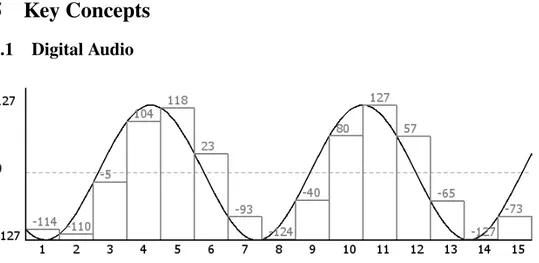
Figure 1: A sine wave is being sampled using 8-bit PCM. The grey bars represent values sampled, whilst the black sine wave represents the audio signal being sampled. The numbers over each bar represent the data that would be stored in a buffer as a result of the sampling.
When computers process or play audio that has been recorded with a microphone, they usually work with PCM data. Analog audio can be represented as a number of waves. Microphones are based on a simple concept: when soundwaves enter the microphone, a membrane inside begins to vibrate. The voltage over the membrane is measured, and as the membrane moves, the voltage measured varies. The computer samples the voltage at a regular interval (often a sample rate of 44100 or 48000 Hz), and
the samples are stored in a buffer. The samples are usually stored as integers of a number of bits – most commonly 16 bits in commercial applications, though other bit rates exist. Figure 1 shows how an analog signal is digitised using PCM.
5.2 IIR Filters
5.2.1 Description
The concept of filtering is an important part of signal processing. In many cases, the purpose is to amplify or attenuate one component of a signal. This allows for a wide range of effects such as a a bass boost (by attenuating high frequencies), an equaliser (by having a number of frequency bands that are attenuated or amplified) or noise reduction (by profiling the noise and constructing a filter that attenuates the frequencies in question). An efficient method of accomplishing this is to make use of IIR or FIR filters. The choice of filter depends upon the application.
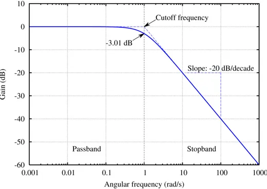
Figure 2: The result of a low-pass filter run on a white-noise signal. Low frequencies pass while high frequencies are attenuated. The dotted line illustrates the ideal scenario, whilst the limitations of using the Butterworth filter are shown on the blue line.[6]
There are many groups of filters. The filters discussed in this report are used to modify the amplitude of frequencies in an audio signal. An example would be to remove some of the bass in an audio signal using a high-pass filter, a filter in which low frequency components are attenuated whilst high frequency signals are untouched in the ideal scenario. Usually a cut-off frequency is picked, a frequency in which a filter transitions from either passing or attenuating frequencies that follow or precede. Figure 2 shows a signal that has been filtered to reduce the amplitude of frequencies above 1 radian/second, a low-pass filter.
A FIR filter is a fairly simple filter. It consists of a number of coefficients that are multiplied with an equal number of input values. The sum of results of the multiplications is the output value. The number of coefficients is referred to as the length of the filter, while the order of the filter is defined as being the length+1. [7] A problem with FIR filters is that the impulse response of a FIR filter cannot be longer than one sample over the order of the filter which limits what can be done with short filters. In order to compensate for this, FIR filters tend to be of a high order which requires a lot of computationally expensive multiplication instructions.
The IIR filter solves this by adding an extra step to the FIR filter. This step involves a feedback component where old output values are fed back to the filter. When a feedback component is added, the maximum impulse response of a filter becomes infinite. This property gives the Infinite Impulse Response (IIR) filter its name.
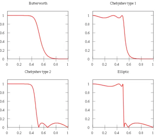
Figure 3:The result of four different filters. All filters are fifth-order IIR-filters. The x-axis displays frequency and the Y-axis displays the amplitude of said frequency. Since low frequencies remain while high frequencies are removed this is a low-pass filter.[8]
The order of a filter determines the characteristics of the filter. There are a number of different filter design methods that have their own advantages and disadvantages, generally varying in the steepness that can be achieved or the possibility that ripples will appear. See figure 3 for a visual representation of how the results of different filter design methods can vary. These problems become less prominent as the order of the filter increases, and thus a higher order filter will generally provide better quality filtering. An application that requires the removal of a a specified frequency from a signal may be hindered by a low-order filter, as the filter may affect nearby frequencies or limit the attenuation that can be achieved.
Difficulties can arise when designing IIR filters of a high order. A high order filter will require more operations to process a sample which affects performance adversely, but beyond that, there is an issue of stability. Any system that produces a bounded result when the input values are bounded is called a stable system.[7] FIR filters are always stable, but the feedback section of the IIR filter can introduce instability when the result is added to previous results.[7] One solution to this problem is to break up a high-order filter into a number of low-order filters that are run one after the other in what is called a cascade. If all low-order filters can be verified to be stable, then the cascade will also be stable as every limited input of every filter has been verified to produce a limited response. Verifying the stability of low-order filters like the biquad is possible, but high-order filters are more sensitive, meaning that small variations in coefficients can snowball and cause instabilty. This also means that minor inaccuracies in the coefficients caused by the limited precision in floating-point and fixed-point representation of real numbers can cause instability.[9]
need to attempt calculation of multiple samples in parallel. This article does not discuss the optimisation of high-order filters, but if stability can be achieved it is a better solution. It also allows for memory variables to be represented as a circle buffer, as the modulo instruction required no longer takes up more cycles than moving the memory buffer forward using assignments.
5.2.2 Implementation
Since IIR filters extend FIR filters it is useful to study the FIR filter before moving on to the IIR filter. As established earlier, the FIR filter is a digital filter that for every sample in an input signal multiplies the current input value as well as a number of previous values with respective coefficients. The sum of the results from these multiplications is the output value. Equation 1 describes the value of an output sample processed using a FIR filter.[10]
y[n] =
M
X
k=0
bkx[n − k] (1)
bkis the feedforward coefficient, x is the input signal, n is the position of the sample being processed,
and M is the order of the FIR filter.
As can be seen in the equation, there is also a limit to how many samples can be affected by a signal impulse. Values that are outside the window given by the order of the FIR filter cannot have any effect on the output signal.[10]
The IIR filter adds a feedback component where previous output values are processed in addition to the input values. The equivalent equation to equation 1 for an IIR filter can be seen in equation 2.
y[n] = N X l=1 aly[n − l] + M X k=0 bkx[n − k] (2)
akis the feedback coefficient, y is the output signal and N is the order of the IIR filter.
In this project all IIR filters will be biquad filters, meaning they’re second order IIR filters. Biquad filters require three values from the input signal and two previous output values, which means that an individual filter requires a minimum of five multiplications in order to run. Whilst IIR filters can improve performance by reducing the number of calculations, they also possess some unique difficulties:
• The feedback component of an IIR filter requires the use of previously computed samples as input values. This creates a difficulty when optimising for NEONTM as every sample depends on the previous result, making parallel calculation of multiple output samples in a single filter impossi-ble. The solution to this is to either find independent data to operate on (such as separate audio channels), or to attempt to run the calculations for a single sample in parallel.
• When low order filters like the biquad are implemented in C, you get relatively short for-loops. This causes problems, as the proportion of time spent loading, storing and advancing the loop is increased. NEONTM is particularly effective at improving the speed of calculations, so with fewer calculations there is a smaller room for improvement. Due to pipeline stalls and overhead in storing and loading NEONTMdata it is possible to end up with worse performance than one started with.
When implementing an IIR filter in code, multiply-accumulate or MAC-instructions prove to be very useful. These are instructions that multiply one value with another and add the result to third value. Regarding the formula for the IIR filter in equation 2, it is clear that every step in the IIR and FIR filters can be performed using these instructions, as every iteration multiplies a number of values with their corresponding coefficients and sums up the results. The ARM CortexR -A9 supports this instructionR
both in normal code and in the NEONTM mode of operation. When estimating the performance of
two implementations, the number of cycles required for a multiply-accumulate or a multiply-subtract instruction (or, as they’re called when dealing with ARM CPUs, the MLA or MULTIPLY-SUBTRACTR
5.3 NEONTM
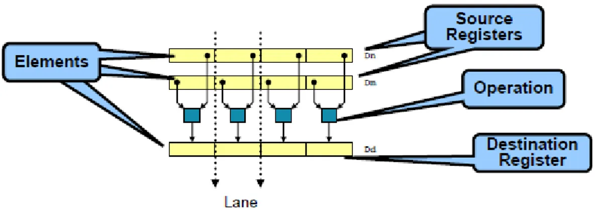
Figure 4:The corresponding elements of two source registers containing four elements each are operated upon by a NEONTM instruction. The same operation is run on all elements, and the result is stored in a result vector. Whilst in normal non-vectorised code this would require four instructions, in NEONTMcode the operations are combined into a single instruction. Permission to use the above image has been granted by ARM Ltd.[11]R
The ARM CortexR -A9 NEONR TMMPE (Media Processing Engine) is an extension of the Cortex -R
A9 CPU that adds instructions useful for media processing. The NEONTMMPE introduces SIMD pro-cessing similar to that of Intel’s SSE or MMX extensions. This means that a single instruction can operate on multiple pieces of data. Figure 4 contains a representation of two vectors that are operated upon, with the result stored in a result vector.
NEONTMcode is particularly efficient for calculations. An example would be the implementation of a gain, an effect that increases the strength of a signal.
In normal C:
f o r ( i = 0 ; i <BUFFERLENGTH ; i + + ) { o u t p u t [ i ] = 1 . 2 ∗ i n p u t [ i ] ; }
The above code processes a single value per iteration. By unrolling the loop, some efficiency may be gained: f o r ( i = 0 ; i <BUFFERLENGTH ; i + = 4 ) { o u t p u t [ i ] = 1 . 2 ∗ i n p u t [ i ] ; o u t p u t [ i + 1 ] = 1 . 2 ∗ i n p u t [ i + 1 ] ; o u t p u t [ i + 2 ] = 1 . 2 ∗ i n p u t [ i + 2 ] ; o u t p u t [ i + 3 ] = 1 . 2 ∗ i n p u t [ i + 3 ] ; }
There is less overhead which will improve performance, and the possibility of dual issuing instruc-tions increases. The problem of the cycle-heavy multiplication instrucinstruc-tions still remains, however. Using NEONTMintrinsics, the code would look quite different:
f o r ( i = 0 ; i <BUFFERLENGTH ; i + = 4 ) { / / l o a d f o u r s a m p l e s s a m p l e s _ f 3 2 = v l d 1 q _ f 3 2 ( i n p u t + i ) ; / / p e r f o r m m u l t i p l i c a t i o n s a m p l e s _ f 3 2 = v m u l q _ f 3 2 ( s a m p l e s _ f 3 2 , 1 . 2 ) ; / / s t o r e r e s u l t s a m p l e s _ f 3 2 = v s t 1 q _ f 3 2 ( o u t p u t + i , s a m p l e s _ f 3 2 ) ; }
• The introduction of additional registers to be used specifically for NEONTM operations. These
registers can be addressed in various ways, however in this project they will be addressed as either 64-bit (double) registers or 128-bit (quad) registers. If, for example, quad registers are being used, one could fit four 32-bit values into a single register. When an instruction is executed, it will execute on all four values in a single instruction, providing up to four times higher performance.[3] • Support for a signed/unsigned 8-bit, 16-bit, 32-bit and 64-bit integer as well as single precision
floating point.[3]
• Support for loading structured loads of data, allowing for interleaving or deinterleaving as data is being loaded/stored.[3]
• Using intrinsics allow for integration with C code[11]. It is therefore not necessary to write any code in assembly while making use of these instructions. This project makes use of intrinsics throughout the system; no assembly is being used at any point.
• Operates asynchronously from ARM execution unit. One must be careful when accessing mem-R
ory, as to do so incorrectly causes CPU stalling which requires tens of cycles to resolve. This is a key problem when optimising with NEON instructions, as mixing NEONTM instructions and regular ARM code often causes enough stalling to negate much of the performance increaseR
from using NEONTM instructions.[12] The solution to this problem has been to keep data in the NEONTMformat for as long as possible.
The performance gains associated with NEONTMcorrespond roughly with the number of values that can fit inside a register, as this is the number of operations that can be done in parallel. This means that the largest performance gains will be seen when processing 8-bit data (16 values can fit in a single register, giving up to 16 times better performance) while small performance gains will be seen when calculating 64-bit data (2x performance gains).
5.4 Fixed-point arithmetic
Fixed-point arithmetic is a method for implementing real numbers using integer variables. The main difference from floating point is that the radix point is given a fixed position which trades flexibility for computational efficiency. In practice, a scaling factor is introduced that decides how many bits will be given to each side of the radix point.
Using fixed-point arithmetic to calculate the result of A · B when A = 2.5 and B = 8.4 using 32-bit integers would involve the following operations:
1. Decide upon a scaling factor. This depends largely upon what kind of numbers are likely to be seen. As the numbers in this example are so low, it is less important, and 16 fractional bits (bits to the right of the radix point) are acceptable. The scaling factor will then be f = 216= 65536. This format is known as Q15.16 (15 bits to the left of the radix point, 16 to the right and one bit for a sign).
2. Scale numbers with the scaling factor. In binary arithmetic this can be accomplished using bit shifts, but for simplicity we will use multiplication by the scaling factor. Ai = A·f = 2.5·65536 =
163840 and B · f = 8.4 · 65536 = 550502.4 which is then truncated turn it into an integer, so Bi= 550502.
3. Multiply Ai and Bi using normal integer multiplication. Ri = Ai · Bi = 163840 · 550502 =
90194247680. The reason for such a large number is that both Ai and Bi were scaled into our
Q15.16 format, so the number that results from the multiplication is essentially (A · f ) · (B · f ) = A · B · f2.
4. In order to bring our result back into the Q15.16 format, the result must thus be divided by the scaling factor. This too can be done using bit shift arithmetic, but for simplicity’s sake division is used here. Ri/f = 90194247680/65536 = 1376255 which is our result in Q15.16 format.
5. To turn the number back into a normal real number, one only needs to cast it into the format desired and divide by the scaling factor again, so: 1376255.0/65536.0 = 20.999985 which is near the expected number 21.
In order to simplify the explanation, the method above makes use of division as opposed to bit shifts. There are two bit shift operations, allowing for shifting left and shifting right. Under the cor-rect conditions it is possible to replace cycle-heavy multiplication instructions with very cycle-light shift instructions. Since they operate on the binary representation of a value, they are usually only used on integers due to the simplicity of representing an integer in binary. Bit shifting cannot replace multipli-cation unless one of the factors can be represented by 2N where N is an integer, and the reason for this becomes clear when one investigates how bit shift operations function.
The very expensive division instructions above can also be replaced with bit shifts. ARM NEON does not perform division[3], so in order to perform a division one has to convert the integer into floating point, multiply by the inverse of the denominator and then convert back to integer form. This is inefficient, so by replacing this with right shifts it is possible to vastly improve performance. A right shift is however not exactly the same as a division by two on two’s complement architectures [13] such as ARM. By using right shifts instead of divisions a rounding error has been introduced, however the impact on sound quality was judged to be minimal.
The ARM CPU used lacks a floating point unit, making integer arithmetic faster than floatingR
point arithmetic. Since floating point arithmetic has to be emulated in software at compile-time, it can therefore be significantly slower. Section 8 contains a comparison between the performance of floating point and fixed point arithmetic.
The loss of precision means that care must be taken when deciding upon a scaling factor to use. There is also a risk of overflow in the intermediate step where you have A·B ·f2. During this intermediate step, one must use a temporary variable twice the bit width of the variables that are being multiplied. This means that in order to multiply any two 32-bit integers, the result needs to be stored in a 64-bit integer in order to avoid overflow. Another option is to saturate the variable when overflow is detected, which allows for 32-bit integers to be used throughout. This is not an option in this project, as the values will be fed into cascading IIR filters where saturated values would produce corruption. Another option is to design the filters and the scaling factor so that they will never overflow, however filter design is outside the scope of this paper.
The only non-risky option then is to use a 64-bit intermediate variable during fixed-point calculations which, due to their large size relative to the size of NEONTM registers, reduces the potential number of samples processed using NEONTMoperation by half.
6
Methodology
To allow for comparison between the different methods of optimisation, four different versions of the effect will be created.
Two tests are performed on each algorithm, one testing just the IIR filter component and one testing the full effect. The reason for this is that some optimisation techniques require preprocessing or addi-tional overhead when implemented in an actual effect, such as format conversion, deinterleaving, and so on. These are not part of the IIR filter itself, yet in an actual audio effect they would be required. They also serves to illustrate how much of an audio effect can be optimised with NEONTM.
For the isolated biquad tests, a buffer of 32768 samples is processed 10000 times. The total amount of time spent in the process is measured and the number of samples per second is calculated. For the full effect, an audio file is processed 20 times. The average time spent in the process is measured and the number of samples per second is calculated.
The effect that is being implemented is an implementation of an audio virtualizer. A reference imple-mentation is created using MATLAB and Simulink, containing five IIR filters, a delay line, a gain, con-version to and from the input format and the processing format, as well as a interleaving/deinterleaving of data.
7
Algorithm and Construction
7.1 Effect Implementation
There are two different structures employed by the four implementations. One is used by the two imple-mentations using NEONTM instructions in the filtering stage and the other for the two implementations that use straight C in the IIR filtering stage.
The structure used by implementations without NEON in the IIR filtering stage is the following: 1. A method is called with an audio buffer as an argument. This audio buffer always consists of 16-bit
signed integers and most commonly contains 400 frames, meaning 800 samples in total for stereo data.
2. The buffer is deinterleaved and converted to the format used by the implementation in question and scaled down to a range of −1 to 1. For the fixed point version this step is done using NEONTM instructions. Due to the interleaving there are now two buffers, one left buffer and one right buffer. 3. Both channels get an additional buffer containing audio that has been delayed a number of samples. 4. Two biquad filters are run on the original buffers and three biquads are run on the delay buffers alongside a gain filter to adjust levels. Since this is done without the use of NEON, there is no way to run left and right channels in parallel. This means that this stage must be run twice, once for the left channel and once for the right channel.
5. The left and right delay channels are mixed with the opposite original channel, meaning the origi-nal right channel is mixed with left delay channel and so on.
6. A softlimiter is used to avoid clipping as the data is converted back to 16-bit signed integer and stored in the output buffers. This step is also done using NEONTMinstructions for the fixed point implementation.
For the versions that use NEONTM instructions in the IIR filtering stage, the following structure is used:
1. A method is called with an audio buffer as an argument. This audio buffer always consists of 16-bit signed integers and most commonly contains 400 frames, meaning 800 samples in total for stereo. 2. The buffer is converted to the format used, either NEONTM-style float32_t or 32-bit signed
inte-gers for fixed point as well as scaled down to a range of −1 to 1. This is done using NEONTM instructions.
3. An extra delay buffer is created. This buffer is interleaved just like the original buffer. Since the two channels have different delay parameters, a deinterleaving is required so the channels can be operated upon on their own. After the delay has been added, the delay channels are interleaved again.
4. Two biquad filters are run on the original buffers and three biquads are run on the delay buffers alongside a gain filter to adjust levels. Since the same filters are run on both left and right channels and because the buffer is interleaved, it is possible to simply point the NEONTMload operation on the left sample (left the first channel when interleaved) and load both left and right samples with
a single instruction. This solves a major issue of how to load data in an efficient manner, as with deinterleaved buffers many more instructions are spent loading samples. Left and right samples are also completely independent, which solves the issue
5. The left and right delay channels are mixed with the opposite original channel, meaning the origi-nal right channel is mixed with left delay channel and so on.
6. A softlimiter is used to avoid clipping as the data is converted back to 16-bit signed integer and stored in the output buffers using NEONTM.
Every filter implementation has two different filter versions. Since the loop in a biquad filter is so short, individual instructions are of significant importance. Some filters given by the MATLAB imple-mentation make use of a scaling factor that scales every input value before using it in calculations. By testing if scaling is necessary (by comparing the value of the scaling factor variable with 1.0), it is pos-sible to skip this operation, which improves performance by around 10% for the full effect. The same scaling factor is used in the entire loop, which means this test can be done outside the loop.
The fixed-point implementations use a Q6.25 format for fixed-point variables. This was decided upon after comparing various formats and picking a format with a good balance between bits before and after the radix point.
7.2 32-bit Floating Point without NEONTM
This implementation is a straight-forward processing of the buffer. This is by far the easiest implemen-tation, however since the CPU does not have a floating point unit, this method is not an ideal solution. It does not make use of NEONTMinstructions at all, and optimisation of the filter is difficult as floating point forces the code to be rather high-level, making the use of shift arithmetic and similar tricks difficult. The code can be seen in Appendix A.1.
7.3 32-bit Fixed Point Version with Limited Use of NEONTMInstructions
Since the CPU used lacks a FPU (other than the one in the NEONTM MPE) making use of integers instead of floating point variables should give a large speed increase. There are several issues, some of which only affect performance and some that affect precision:
• After every multiplication, a shift is required to return the value to the format being used. The effect of this can be lessened in some circumstances, such as in the IIR filter. In the implementation used, the five multiplications of the filter are added and then shifted just once. This has the same effect as shifting first and then adding, but at a much lower instruction cycle cost. For most purposes this requires the use of a 64-bit intermediate variable to store the values to avoid overflow, but making use of a 64-bit intermediary may be necessary even when multiplying just two values.
• Every variable, filter coefficient, scaling factor and so on must be converted to the format used which is an additional step. It must also be returned to the format used by the interface when storing the value.
• When using a right shift to divide integers, there can be issues where some operations do not always result in the expected value. The reason for this is that an arithmetic right shift on a number always rounds to the nearest integer that is less than or equal to the actual result on two’s-complement systems such as ARM. [13] However, with the format used there exists a relatively large amount of room for small rounding errors, as there are more than enough bits after the radix point, and so this has not been a problem in any of the tests performed.
There is some use of NEONTMinstructions in this version, however none of them are in the actual IIR filtering. The softlimiter, deinterleaving and format conversion all make use of NEONTM instructions. The code can be seen in Appendix A.2.
7.4 32-bit Floating Point Version with NEONTMInstructions
This version is very similar to the fixed-point NEONTMversion, with the obvious difference that it makes use of floating point variables. The NEONTMMPE actually supports floating point instructions, however there is some loss of performance compared to the integer versions of corresponding instructions. An example would be the VMLA (vector MLA) instruction where a signed integer 32-bit VMLA requires 7 cycles for the full operation (assuming a vector size of 64-bits) whereas the floating-point equivalent requires 10 cycles. This is not a completely fair comparison, as the fixed-point version would require a shift afterwards and there is some concurrency in the CPU due to the superscalar nature of the CPU, but it serves to illustrate to some degree the level of performance to be expected.[3]
A substantial amount of the execution time is spent performing various load and store operations. In early versions of the effect implementation values were stored in normal registers whenever they were not being operated upon by NEONTMcode, however this was detrimental to the point where even though the calculations were running twice as fast, the data shuffling and possibly stalling issues made the NEONTM versions slower than the non-NEONTMversions. It is therefore not enough to simply rewrite a function in NEONTM, care must be taken to move data around in an efficient manner. The fact that code being written using NEONTMintrinsics makes the code fairly low-level is beneficial here, as a great amount of control is achieved.
Even though the use of floating-point instructions allows for operation on four pieces of data per instruction, only two are used. The reason for this is that every iteration of the IIR filter depends on the result of the previous iteration. Since there are only two channels, there are only two independent operations that can be performed. This could possibly be worked around in a future version where two independent filters are run at the same time. An example of this would be the simultaneous filtering of the delay channels and the original channels, however when this was attempted the amount of data shuffling that had to take place negated any performance improvement. The code can be seen in Appendix A.3.
7.5 32-bit Fixed Point Version with NEONTMInstructions
This implementation requires the most amount of time to implement in a satisfactory manner. A 64-bit intermediate register is used for the multiply-accumulate operations, allowing for the use of a single shift-instruction per iteration as opposed to one per multiplication, as there is no risk of overflow. This has the effect of limiting the number of samples that can be processed per iteration to two, as only two 64-bit values can fit in a 128-bit NEONTMregister, but this is a relatively minor issue as only two samples (left and right audio channels) are independent when executing any single filter. It does, however, limit the potential for future optimisation as two independent filters cannot run at the same time, as would theoretically be possible with the floating-point equivalent. The code can be seen in Appendix A.4.
8
Results
The four versions of the algorithm are compared.
Implementation Full effect Isolated biquad Floating point w/o NEONTMinstructions 1.3 10 Fixed point w/o NEONTMinstructions 2.8 20 Floating point w/ NEONTMinstructions 4.0 41 Fixed point w/ NEONTMinstructions 4.8 56
Higher numbers indicate better performance as more samples can be processed in a given timeframe. The measurements only consider time spent in the actual process. All numbers stated are in MSamples/s.
9
Conclusion
Even when the NEONTMMPE is held back by the inability to process more than one iteration at a time and with IIR filters as short as biquads, the performance increase seen by using NEONTMinstructions is greater than the most common conventional method, the use of fixed-point arithmetic.
The results show that the fixed-point version using NEONTM instructions provides the best perfor-mance, which is to be expected. However, the performance reached is remarkably close to the floating point NEONTM implementation, which comes as a surprise. Looking through the ARM NEONR TM
technical reference manual, the reason for this becomes clear as the IIR filter primarily consists of a number of VMLA and VMLS instructions. The floating point version of this instruction requires 10 cy-cles from start to writeback, whereas the integer version needs just 7 cycy-cles, which means that the fixed point version should be about 42% faster than the floating point version. The fixed point version however requires a shift whenever a multiplication has been done, and while this has been implemented efficiently with just a single shift instruction for all five of the VMLA/VMLS instructions, there is also the matter of the use of 64-bit variables which are not natively supported by the ARM CPU. Considering theseR
facts, the 20% performance increase in the full effect and the 37% increase for a single filter is not too far from what would be expected.[3]
When deciding whether to use fixed-point or floating-point, there are a number of factors to consider. Use of floating-point has the advantage of being safer than fixed-point implementations as there is less risk of overflow or errors related to integer division using binary shifts. When using floating point instructions it is possible to apply the filter without ever having to use 64-bit variables. This makes it possible to simultaneously process four samples. It is also considerably easier to use floating-point instructions, both in a planning stage and in the later stage of implementation.
The fixed-point NEONTMversion has the advantage of being faster than the floating-point equivalent, but as the results show, the difference is large but not overwhelmingly so, likely due to the support for floating-point instructions in the NEONTM MPE. If an IIR filter can be implemented using 16-bit integers, the performance gap could increase as these instructions are both faster and allow for more elements per vector. There is no equivalent in the floating-point instructions, as only 32-bit floats are available when using NEONTMinstructions. Use of fixed-point arithmetic allows for other performance increasing tricks, such as shift multiplication/division, binary operations and so on. This is of no great importance in an IIR filter, as the multiply-accumulate instructions normally cannot simply be replaced with binary operations, but it can still be a factor.
When optimising for the NEONTMMPE, the recursive property of IIR filters provides a difficulty in that no more than one iteration per filter can be run simultaneously. This is further complicated by the low order biquads used in this report as only a few optimisable operations occur every iteration. It is preferable to run a high-order filter in place of a cascade of low-order biquads as one could instead focus on running the operations of a single IIR filter in parallel, rather than running multiple independent filters at once on NEONTMMPE. This would, in theory, allow for a large number of simultaneous operations.
It is interesting to note that the lower level code of the NEONTM versions allows for optimisation beyond what would be expected from comparing the cycle timings of the MLA instructions. The fixed-point NEONTMis 2.83 times faster than the normal fixed-point implementation, which is likely caused by the improvements in memory management that can be achieved when code is as low-level as it is in the NEONTMimplementation.
There are a number of areas where further work would be of interest. Finding a way to efficiently make use of the entire NEONTMregister in the floating point implementation would certainly be a chal-lenge, and is most likely possible. A trivial solution to this problem would be to implement an effect on a system with more than two channels such as video or surround sound. It would also be interesting to compare a fixed-point implementation with a floating-point implementation on an ARM CPU withR
a FPU. A more advanced solution would be to make use of an algorithm for fusing coefficients such as the one described in "Parallellization of IIR filters using SIMD extensions" [4]. The implementation described in the paper would require a full register, however if modified to work with 64-bit registers it’d be possible to fuse coefficients as well as filter two channels simultaneously.
Another area of interest would be techniques that require higher order filters, such as the use of NEONTM within a single channel as well as efficient modelling of the storage of old output and input
References
[1] Intel Corporation. Fir and iir filtering using streaming simd extensions. Intel Application Notes, 1999.
[2] Frederik Fabritius. Audio processing algorithms on the gpu. 2009.
[3] ARM. CortexTM-a9 neonTM media processing engine, revision: r2p2, technical reference manual. http://infocenter.arm.com/help/topic/com.arm.doc.ddi0409f/ DDI0409F_cortex_a9_neon_mpe_r2p2_trm.pdf, August 24 2011.
[4] Rade Kutil. Parallelization of iir filters using simd extensions. IWSSIP, 2008.
[5] Jon García de Salazar Ochoa. Optimización de funciones de dsp para procesador con instrucciones simd. 2008.
[6] Wikipedia Omegatron. Butterworth response. http://en.wikipedia.org/wiki/File: Butterworth_response.png, September 1 2011.
[7] J.H. McClellen, R.W. Schafer, and M.A. Yoder. DSP first: a multimedia approach. Number v. 1 in MATLAB curriculum series. Prentice Hall, 1998.
[8] Alessio Damato. Electronic linear filters. http://en.wikipedia.org/wiki/File: Electronic_linear_filters.svg, September 1 2011.
[9] L.B. Jackson. Digital filters and signal processing: with MATLAB exercises. Kluwer Academic Publishers, 1996.
[10] Mark A. Yoder James H. McClellan, Ronald W. Schafer. Signal Processing First, International Edition. Pearson Prentice Hall, 2003.
[11] Venu Gopal Reddy. Neon technology introduction. www.arm.com/files/pdf/AT_-_ NEON_for_Multimedia_Applications.pdf, August 24 2011.
[12] Måns Rullgård. Arm-neon memory hazards. http://hardwarebug.org/2008/12/31/ arm-neon-memory-hazards/, September 1 2011.
[13] Donald Knuth. The Art Of Computer Programming 3rd ed. Volume 2. Addison Wesley Longman, 1997.
A
Code Samples
A.1 Floating-Point Filter
v o i d i i r f i l t e r ( f l o a t 3 2 _ t ∗ i n , i n t b u f f e r s i z e , f l o a t 3 2 _ t ∗ xmem , f l o a t 3 2 _ t ∗ ymem , f l o a t 3 2 _ t s c a l e , f l o a t 3 2 _ t ∗ c o e f f s ) { i n t i = 0 ; f o r ( i = 0 ; i < b u f f e r s i z e ; i ++) { xmem [ 0 ] = xmem [ 1 ] ; xmem [ 1 ] = xmem [ 2 ] ; xmem [ 2 ] = ( ∗ i n ) ∗ s c a l e ; ymem [ 0 ] = ymem [ 1 ] ; ymem [ 1 ] = ymem [ 2 ] ; ymem [ 2 ] = xmem [ 0 ] ∗ c o e f f s [ 2 ] ; ymem [ 2 ] += xmem [ 1 ] ∗ c o e f f s [ 1 ] ; ymem [ 2 ] += xmem [ 2 ] ∗ c o e f f s [ 0 ] ; ymem [ 2 ] −= ymem [ 0 ] ∗ c o e f f s [ 4 ] ; ymem [ 2 ] −= ymem [ 1 ] ∗ c o e f f s [ 3 ] ; ∗ i n = ymem [ 2 ] ; i n + + ; } } v o i d i i r f i l t e r _ u n s c a l e d ( f l o a t 3 2 _ t ∗ i n , i n t b u f f e r s i z e , f l o a t 3 2 _ t ∗ xmem , f l o a t 3 2 _ t ∗ ymem , f l o a t 3 2 _ t s c a l e , f l o a t 3 2 _ t ∗ c o e f f s ) { i n t i = 0 ; f o r ( i = 0 ; i < b u f f e r s i z e ; i ++) { xmem [ 0 ] = xmem [ 1 ] ; xmem [ 1 ] = xmem [ 2 ] ; xmem [ 2 ] = ∗ i n ; ymem [ 0 ] = ymem [ 1 ] ; ymem [ 1 ] = ymem [ 2 ] ; ymem [ 2 ] = xmem [ 0 ] ∗ c o e f f s [ 2 ] ; ymem [ 2 ] += xmem [ 1 ] ∗ c o e f f s [ 1 ] ; ymem [ 2 ] += xmem [ 2 ] ∗ c o e f f s [ 0 ] ; ymem [ 2 ] −= ymem [ 0 ] ∗ c o e f f s [ 4 ] ; ymem [ 2 ] −= ymem [ 1 ] ∗ c o e f f s [ 3 ] ; ∗ i n = ymem [ 2 ] ; i n + + ; } }
A.2 Fixed-Point Filter
v o i d i i r f i l t e r ( _ _ r e s t r i c t i n t 3 2 _ t ∗ i n , i n t b u f f e r s i z e , i n t 3 2 _ t ∗ xmem , i n t 3 2 _ t ∗ ymem , i n t 3 2 _ t s c a l e , _ _ r e s t r i c t i n t 3 2 _ t ∗ c o e f f s ) { i n t i = 0 ; i n t 6 4 _ t a c c ; f o r ( i = 0 ; i < b u f f e r s i z e ; i ++) { xmem [ 0 ] = xmem [ 1 ] ; xmem [ 1 ] = xmem [ 2 ] ; xmem [ 2 ] = ( ( ∗ i n ) ∗ ( i n t 6 4 _ t ) s c a l e ) > >EXPO ; ymem [ 0 ] = ymem [ 1 ] ; ymem [ 1 ] = ymem [ 2 ] ; a c c = ( xmem [ 0 ] ∗ ( i n t 6 4 _ t ) c o e f f s [ 2 ] ) ; a c c += ( xmem [ 1 ] ∗ ( i n t 6 4 _ t ) c o e f f s [ 1 ] ) ; a c c += ( xmem [ 2 ] ∗ ( i n t 6 4 _ t ) c o e f f s [ 0 ] ) ; a c c −= ( ymem [ 0 ] ∗ ( i n t 6 4 _ t ) c o e f f s [ 4 ] ) ; a c c −= ( ymem [ 1 ] ∗ ( i n t 6 4 _ t ) c o e f f s [ 3 ] ) ; ymem [ 2 ] = ( i n t 3 2 _ t ) ( a c c >>EXPO ) ; ∗ i n = ymem [ 2 ] ; i n + + ; }
} / ∗ F i l t e r u s e d when no s c a l i n g o f i n p u t v a l u e s i s r e q u i r e d , s l i g h t l y f a s t e r t h a n a b o v e v e r s i o n . ∗ / v o i d i i r f i l t e r _ u n s c a l e d ( _ _ r e s t r i c t i n t 3 2 _ t ∗ i n , i n t b u f f e r s i z e , i n t 3 2 _ t ∗ xmem , i n t 3 2 _ t ∗ ymem , _ _ r e s t r i c t i n t 3 2 _ t ∗ c o e f f s ) { i n t i = 0 ; i n t 6 4 _ t a c c ; f o r ( i = 0 ; i < b u f f e r s i z e ; i ++) { xmem [ 0 ] = xmem [ 1 ] ; xmem [ 1 ] = xmem [ 2 ] ; xmem [ 2 ] = ∗ i n ; ymem [ 0 ] = ymem [ 1 ] ; ymem [ 1 ] = ymem [ 2 ] ; a c c = ( xmem [ 0 ] ∗ ( i n t 6 4 _ t ) c o e f f s [ 2 ] ) ; a c c += ( xmem [ 1 ] ∗ ( i n t 6 4 _ t ) c o e f f s [ 1 ] ) ; a c c += ( xmem [ 2 ] ∗ ( i n t 6 4 _ t ) c o e f f s [ 0 ] ) ; a c c −= ( ymem [ 0 ] ∗ ( i n t 6 4 _ t ) c o e f f s [ 4 ] ) ; a c c −= ( ymem [ 1 ] ∗ ( i n t 6 4 _ t ) c o e f f s [ 3 ] ) ; ymem [ 2 ] = ( i n t 3 2 _ t ) ( a c c >>EXPO ) ; ∗ i n = ymem [ 2 ] ; i n + + ; } }
A.3 Floating-Point NEONTM Filter / ∗
I I R f i l t e r t o u s e f o r f i l t e r s w h e r e t h e i n p u t n e e d s t o be s c a l e d . XMEM and YMEM a r e n e c e s s a r y i n o r d e r t o a l l o w p r o c e s s i n g i n c h u n k s . XMEM c o n t a i n s v a l u e s u s e d i n t h e f e e d f o r w a r d p a r t o f t h e f i l t e r and YMEM
c o n t a i n s v a l u e s u s e d i n f e e d b a c k . Even i n d i c e s a r e l e f t c h a n n e l , odd i n d i c e s a r e r i g h t c h a n n e l ∗ / v o i d i i r f i l t e r ( _ _ r e s t r i c t i n t 3 2 _ t ∗ i n , i n t b u f f e r s i z e , i n t 3 2 _ t ∗ xmem , i n t 3 2 _ t ∗ ymem , i n t 3 2 _ t s c a l e , _ _ r e s t r i c t i n t 3 2 _ t ∗ c o e f f s ) { i n t 6 4 x 2 _ t r e s u l t _ s 6 4 , p c m v e c t o r 2 _ s 6 4 ; i n t 3 2 x 2 _ t r e s u l t _ s 3 2 , p c m v e c t o r 0 , p c m v e c t o r 1 , p c m v e c t o r 2 , p c m v e c t o r 3 , p c m v e c t o r 4 , p c m v e c t o r 5 ; i n t i = 0 ; / ∗
I n d i c e s i n XMEM and YMEM c o r r e s p o n d t o t h e f o l l o w v a l u e s : 0 1 2 3 4 5 L1 R1 L2 R2 L3 R3 Most r e c e n t i s s t o r e d i n L3 / R3 , o l d e s t i s s t o r e d i n L1 / R1 ∗ / p c m v e c t o r 0 = v l d 1 _ s 3 2 ( xmem ) ; p c m v e c t o r 1 = v l d 1 _ s 3 2 ( xmem + 2 ) ; p c m v e c t o r 2 = v l d 1 _ s 3 2 ( xmem + 4 ) ; p c m v e c t o r 3 = v l d 1 _ s 3 2 ( ymem ) ; p c m v e c t o r 4 = v l d 1 _ s 3 2 ( ymem + 2 ) ; p c m v e c t o r 5 = v l d 1 _ s 3 2 ( ymem + 4 ) ; f o r ( i = 0 ; i < b u f f e r s i z e ; i +=2) { / / b u f f e r s a r e i n t e r l e a v e d ( L−R ) p c m v e c t o r 0 = p c m v e c t o r 1 ; p c m v e c t o r 1 = p c m v e c t o r 2 ; p c m v e c t o r 2 = v l d 1 _ s 3 2 ( i n + i ) ; p c m v e c t o r 2 _ s 6 4 = v m u l l _ n _ s 3 2 ( p c m v e c t o r 2 , s c a l e ) ; / / s c a l e v a l u e p c m v e c t o r 2 = v s h r n _ n _ s 6 4 ( p c m v e c t o r 2 _ s 6 4 , EXPO ) ; / / s h i f t and r e t u r n t o 32 b i t p c m v e c t o r 3 = p c m v e c t o r 4 ; p c m v e c t o r 4 = p c m v e c t o r 5 ; r e s u l t _ s 6 4 = v m u l l _ n _ s 3 2 ( p c m v e c t o r 0 , c o e f f s [ 2 ] ) ; / / FIR p a r t r e s u l t _ s 6 4 = v m l a l _ n _ s 3 2 ( r e s u l t _ s 6 4 , p c m v e c t o r 1 , c o e f f s [ 1 ] ) ; / / FIR p a r t r e s u l t _ s 6 4 = v m l a l _ n _ s 3 2 ( r e s u l t _ s 6 4 , p c m v e c t o r 2 , c o e f f s [ 0 ] ) ; / / FIR p a r t r e s u l t _ s 6 4 = v m l s l _ n _ s 3 2 ( r e s u l t _ s 6 4 , p c m v e c t o r 3 , c o e f f s [ 4 ] ) ; / / I I R p a r t
r e s u l t _ s 6 4 = v m l s l _ n _ s 3 2 ( r e s u l t _ s 6 4 , p c m v e c t o r 4 , c o e f f s [ 3 ] ) ; / / I I R p a r t r e s u l t _ s 3 2 = v s h r n _ n _ s 6 4 ( r e s u l t _ s 6 4 , EXPO ) ; / / s h i f t EXPO s t e p s r i g h t , c o n v e r t 64− b i t > 32− b i t v s t 1 _ s 3 2 ( i n + i , r e s u l t _ s 3 2 ) ; / / s t o r e i n b u f f e r p c m v e c t o r 5 = r e s u l t _ s 3 2 ; } v s t 1 _ s 3 2 ( xmem , p c m v e c t o r 0 ) ; v s t 1 _ s 3 2 ( xmem+ 2 , p c m v e c t o r 1 ) ; v s t 1 _ s 3 2 ( xmem+ 4 , p c m v e c t o r 2 ) ; v s t 1 _ s 3 2 ( ymem , p c m v e c t o r 3 ) ; v s t 1 _ s 3 2 ( ymem+ 2 , p c m v e c t o r 4 ) ; v s t 1 _ s 3 2 ( ymem+ 4 , p c m v e c t o r 5 ) ; } / ∗ F i l t e r u s e d when no s c a l i n g o f i n p u t v a l u e s i s r e q u i r e d , s l i g h t l y f a s t e r t h a n a b o v e v e r s i o n . ∗ / v o i d i i r f i l t e r _ u n s c a l e d ( _ _ r e s t r i c t i n t 3 2 _ t ∗ i n , i n t b u f f e r s i z e , i n t 3 2 _ t ∗ xmem , i n t 3 2 _ t ∗ ymem , _ _ r e s t r i c t i n t 3 2 _ t ∗ c o e f f s ) { i n t 6 4 x 2 _ t r e s u l t _ s 6 4 , p c m v e c t o r 2 _ s 6 4 ; i n t 3 2 x 2 _ t r e s u l t _ s 3 2 , p c m v e c t o r 0 , p c m v e c t o r 1 , p c m v e c t o r 2 , p c m v e c t o r 3 , p c m v e c t o r 4 , p c m v e c t o r 5 ; i n t i = 0 ; p c m v e c t o r 0 = v l d 1 _ s 3 2 ( xmem ) ; p c m v e c t o r 1 = v l d 1 _ s 3 2 ( xmem + 2 ) ; p c m v e c t o r 2 = v l d 1 _ s 3 2 ( xmem + 4 ) ; p c m v e c t o r 3 = v l d 1 _ s 3 2 ( ymem ) ; p c m v e c t o r 4 = v l d 1 _ s 3 2 ( ymem + 2 ) ; r e s u l t _ s 3 2 = v l d 1 _ s 3 2 ( ymem + 4 ) ; f o r ( i = 0 ; i < b u f f e r s i z e ; i +=2) { / / b u f f e r s a r e i n t e r l e a v e d ( L−R ) p c m v e c t o r 0 = p c m v e c t o r 1 ; p c m v e c t o r 1 = p c m v e c t o r 2 ; p c m v e c t o r 2 = v l d 1 _ s 3 2 ( i n + i ) ; p c m v e c t o r 3 = p c m v e c t o r 4 ; p c m v e c t o r 4 = r e s u l t _ s 3 2 ; r e s u l t _ s 6 4 = v m u l l _ n _ s 3 2 ( p c m v e c t o r 0 , c o e f f s [ 2 ] ) ; r e s u l t _ s 6 4 = v m l a l _ n _ s 3 2 ( r e s u l t _ s 6 4 , p c m v e c t o r 1 , c o e f f s [ 1 ] ) ; r e s u l t _ s 6 4 = v m l a l _ n _ s 3 2 ( r e s u l t _ s 6 4 , p c m v e c t o r 2 , c o e f f s [ 0 ] ) ; r e s u l t _ s 6 4 = v m l s l _ n _ s 3 2 ( r e s u l t _ s 6 4 , p c m v e c t o r 3 , c o e f f s [ 4 ] ) ; r e s u l t _ s 6 4 = v m l s l _ n _ s 3 2 ( r e s u l t _ s 6 4 , p c m v e c t o r 4 , c o e f f s [ 3 ] ) ; r e s u l t _ s 3 2 = v s h r n _ n _ s 6 4 ( r e s u l t _ s 6 4 , EXPO ) ; v s t 1 _ s 3 2 ( i n + i , r e s u l t _ s 3 2 ) ; } v s t 1 _ s 3 2 ( xmem , p c m v e c t o r 0 ) ; v s t 1 _ s 3 2 ( xmem+ 2 , p c m v e c t o r 1 ) ; v s t 1 _ s 3 2 ( xmem+ 4 , p c m v e c t o r 2 ) ; v s t 1 _ s 3 2 ( ymem , p c m v e c t o r 3 ) ; v s t 1 _ s 3 2 ( ymem+ 2 , p c m v e c t o r 4 ) ; v s t 1 _ s 3 2 ( ymem+ 4 , r e s u l t _ s 3 2 ) ; }
A.4 Fixed-Point NEONTM Filter
v o i d i i r f i l t e r ( _ _ r e s t r i c t i n t 3 2 _ t ∗ i n , i n t b u f f e r s i z e , i n t 3 2 _ t ∗ xmem , i n t 3 2 _ t ∗ ymem , i n t 3 2 _ t s c a l e , _ _ r e s t r i c t i n t 3 2 _ t ∗ c o e f f s ) { i n t 6 4 x 2 _ t r e s u l t _ s 6 4 , p c m v e c t o r 2 _ s 6 4 ; i n t 3 2 x 2 _ t r e s u l t _ s 3 2 , p c m v e c t o r 0 , p c m v e c t o r 1 , p c m v e c t o r 2 , p c m v e c t o r 3 , p c m v e c t o r 4 , p c m v e c t o r 5 ; i n t i = 0 ; / ∗
I n d i c e s i n XMEM and YMEM c o r r e s p o n d t o t h e f o l l o w v a l u e s : 0 1 2 3 4 5 L1 R1 L2 R2 L3 R3 Most r e c e n t i s s t o r e d i n L3 / R3 , o l d e s t i s s t o r e d i n L1 / R1 ∗ / p c m v e c t o r 0 = v l d 1 _ s 3 2 ( xmem ) ; p c m v e c t o r 1 = v l d 1 _ s 3 2 ( xmem + 2 ) ; p c m v e c t o r 2 = v l d 1 _ s 3 2 ( xmem + 4 ) ; p c m v e c t o r 3 = v l d 1 _ s 3 2 ( ymem ) ; p c m v e c t o r 4 = v l d 1 _ s 3 2 ( ymem + 2 ) ; p c m v e c t o r 5 = v l d 1 _ s 3 2 ( ymem + 4 ) ; f o r ( i = 0 ; i < b u f f e r s i z e ; i +=2) { / / b u f f e r s a r e i n t e r l e a v e d ( L−R )
p c m v e c t o r 0 = p c m v e c t o r 1 ; p c m v e c t o r 1 = p c m v e c t o r 2 ; p c m v e c t o r 2 = v l d 1 _ s 3 2 ( i n + i ) ; p c m v e c t o r 2 _ s 6 4 = v m u l l _ n _ s 3 2 ( p c m v e c t o r 2 , s c a l e ) ; / / s c a l e v a l u e p c m v e c t o r 2 = v s h r n _ n _ s 6 4 ( p c m v e c t o r 2 _ s 6 4 , EXPO ) ; / / s h i f t and r e t u r n t o 32 b i t p c m v e c t o r 3 = p c m v e c t o r 4 ; p c m v e c t o r 4 = p c m v e c t o r 5 ; r e s u l t _ s 6 4 = v m u l l _ n _ s 3 2 ( p c m v e c t o r 0 , c o e f f s [ 2 ] ) ; / / FIR p a r t r e s u l t _ s 6 4 = v m l a l _ n _ s 3 2 ( r e s u l t _ s 6 4 , p c m v e c t o r 1 , c o e f f s [ 1 ] ) ; / / FIR p a r t r e s u l t _ s 6 4 = v m l a l _ n _ s 3 2 ( r e s u l t _ s 6 4 , p c m v e c t o r 2 , c o e f f s [ 0 ] ) ; / / FIR p a r t r e s u l t _ s 6 4 = v m l s l _ n _ s 3 2 ( r e s u l t _ s 6 4 , p c m v e c t o r 3 , c o e f f s [ 4 ] ) ; / / I I R p a r t r e s u l t _ s 6 4 = v m l s l _ n _ s 3 2 ( r e s u l t _ s 6 4 , p c m v e c t o r 4 , c o e f f s [ 3 ] ) ; / / I I R p a r t r e s u l t _ s 3 2 = v s h r n _ n _ s 6 4 ( r e s u l t _ s 6 4 , EXPO ) ; / / s h i f t EXPO s t e p s r i g h t , c o n v e r t 64− b i t > 32− b i t v s t 1 _ s 3 2 ( i n + i , r e s u l t _ s 3 2 ) ; / / s t o r e i n b u f f e r p c m v e c t o r 5 = r e s u l t _ s 3 2 ; } v s t 1 _ s 3 2 ( xmem , p c m v e c t o r 0 ) ; v s t 1 _ s 3 2 ( xmem+ 2 , p c m v e c t o r 1 ) ; v s t 1 _ s 3 2 ( xmem+ 4 , p c m v e c t o r 2 ) ; v s t 1 _ s 3 2 ( ymem , p c m v e c t o r 3 ) ; v s t 1 _ s 3 2 ( ymem+ 2 , p c m v e c t o r 4 ) ; v s t 1 _ s 3 2 ( ymem+ 4 , p c m v e c t o r 5 ) ; } / ∗ F i l t e r u s e d when no s c a l i n g o f i n p u t v a l u e s i s r e q u i r e d S l i g h t l y f a s t e r t h a n a b o v e v e r s i o n . ∗ / v o i d i i r f i l t e r _ u n s c a l e d ( _ _ r e s t r i c t i n t 3 2 _ t ∗ i n , i n t b u f f e r s i z e , i n t 3 2 _ t ∗ xmem , i n t 3 2 _ t ∗ ymem , _ _ r e s t r i c t i n t 3 2 _ t ∗ c o e f f s ) { i n t 6 4 x 2 _ t r e s u l t _ s 6 4 , p c m v e c t o r 2 _ s 6 4 ; i n t 3 2 x 2 _ t r e s u l t _ s 3 2 , p c m v e c t o r 0 , p c m v e c t o r 1 , p c m v e c t o r 2 , p c m v e c t o r 3 , p c m v e c t o r 4 , p c m v e c t o r 5 ; i n t i = 0 ; p c m v e c t o r 0 = v l d 1 _ s 3 2 ( xmem ) ; p c m v e c t o r 1 = v l d 1 _ s 3 2 ( xmem + 2 ) ; p c m v e c t o r 2 = v l d 1 _ s 3 2 ( xmem + 4 ) ; p c m v e c t o r 3 = v l d 1 _ s 3 2 ( ymem ) ; p c m v e c t o r 4 = v l d 1 _ s 3 2 ( ymem + 2 ) ; r e s u l t _ s 3 2 = v l d 1 _ s 3 2 ( ymem + 4 ) ; f o r ( i = 0 ; i < b u f f e r s i z e ; i +=2) { / / b u f f e r s a r e i n t e r l e a v e d ( L−R ) p c m v e c t o r 0 = p c m v e c t o r 1 ; p c m v e c t o r 1 = p c m v e c t o r 2 ; p c m v e c t o r 2 = v l d 1 _ s 3 2 ( i n + i ) ; p c m v e c t o r 3 = p c m v e c t o r 4 ; p c m v e c t o r 4 = r e s u l t _ s 3 2 ; r e s u l t _ s 6 4 = v m u l l _ n _ s 3 2 ( p c m v e c t o r 0 , c o e f f s [ 2 ] ) ; r e s u l t _ s 6 4 = v m l a l _ n _ s 3 2 ( r e s u l t _ s 6 4 , p c m v e c t o r 1 , c o e f f s [ 1 ] ) ; r e s u l t _ s 6 4 = v m l a l _ n _ s 3 2 ( r e s u l t _ s 6 4 , p c m v e c t o r 2 , c o e f f s [ 0 ] ) ; r e s u l t _ s 6 4 = v m l s l _ n _ s 3 2 ( r e s u l t _ s 6 4 , p c m v e c t o r 3 , c o e f f s [ 4 ] ) ; r e s u l t _ s 6 4 = v m l s l _ n _ s 3 2 ( r e s u l t _ s 6 4 , p c m v e c t o r 4 , c o e f f s [ 3 ] ) ; r e s u l t _ s 3 2 = v s h r n _ n _ s 6 4 ( r e s u l t _ s 6 4 , EXPO ) ; v s t 1 _ s 3 2 ( i n + i , r e s u l t _ s 3 2 ) ; } v s t 1 _ s 3 2 ( xmem , p c m v e c t o r 0 ) ; v s t 1 _ s 3 2 ( xmem+ 2 , p c m v e c t o r 1 ) ; v s t 1 _ s 3 2 ( xmem+ 4 , p c m v e c t o r 2 ) ; v s t 1 _ s 3 2 ( ymem , p c m v e c t o r 3 ) ; v s t 1 _ s 3 2 ( ymem+ 2 , p c m v e c t o r 4 ) ; v s t 1 _ s 3 2 ( ymem+ 4 , r e s u l t _ s 3 2 ) ; }