Degree project in
Communication Systems
Second level, 30.0 HEC
Stockholm, Sweden
D E N I Z A K K A Y A
Wireless Inspirational Bits for
Facilitating Early Design
K T H I n f o r m a t i o n a n d C o m m u n i c a t i o n T e c h n o l o g y
Information and Communication Technology KTH, Kungliga Tekniska H¨ogskolan
SE-100 44 Stockholm Sweden
Wireless Inspirational Bits for Facilitating
Early Design
May 6, 2013
Deniz E. Akkaya
Degree Project in Communication Systems
Second Level, 30.0 HEC Stockholm, Sweden
Contents
1 Introduction 1
1.1 Low Power Technologies . . . 2
1.2 Role of Wireless Technology . . . 2
1.3 Internet of Things . . . 3
1.4 Internet Services with IoT Vision . . . 4
1.5 Earl Toolkit . . . 4
2 Background Work 7 2.1 Need of a toolkit . . . 7
2.1.1 What is a Toolkit . . . 7
2.1.2 Sketching and Prototyping . . . 8
2.1.2.1 Sketching in Hardware and Software . . . 8
2.1.2.2 Do It Yourself Technology . . . 9
2.2 Current Toolkits . . . 9
2.2.1 Arduino . . . 9
2.2.2 mBed . . . 10
2.2.3 Other Toolkits . . . 11
3 Earl: Toolkit for Sketching 12 3.1 System Description . . . 12
3.2 Design Objectives . . . 12
3.3 Requirements . . . 14
3.3.1 Earl Toolkit Requirements . . . 14
3.3.1.1 Hardware Requirements . . . 14
3.3.1.2 Embedded Software Requirements . . . 16
3.3.2 Mobile Application Requirements . . . 18
3.3.3 Web Service Requirements . . . 18
3.4 Technologies for Earl . . . 19
3.4.1 Wireless Communication Technologies . . . 19
3.4.1.1 Bluetooth . . . 19
3.4.1.2 ZigBee . . . 20
3.4.1.3 WiFi . . . 21
3.4.1.4 ANT . . . 22
3.4.2 Low Power Technologies . . . 23
3.4.3 Low Power Units of Earl . . . 25
4 Implementation 26 4.1 Earl Toolkit . . . 26
4.1.1 Hardware Design . . . 26
4.1.1.1 PCB Design . . . 26
4.1.1.2 Modules and Components Used in Hardware Toolkit . . . 27
4.1.1.2.1 Battery . . . 27
4.1.1.2.2 TPS77333 Voltage Regulator Module . . . 27
4.1.1.2.3 MSP430G2553 Microcontroller Module . . . 29 i
CONTENTS ii
4.1.1.2.4 ANT nRF24AP2 Module . . . 30
4.1.1.2.5 DRV8601 Haptic Driver Module . . . 31
4.1.1.2.6 Connectors and LEDs . . . 32
4.1.2 Embedded Software Design . . . 33
4.1.2.1 Embedded Software Architecture . . . 33
4.1.2.1.1 Constants Module . . . 33 4.1.2.1.2 Base Module . . . 34 4.1.2.1.3 Flash Module . . . 34 4.1.2.1.4 UART Module . . . 34 4.1.2.1.5 ADC Module . . . 35 4.1.2.1.6 PWM Module . . . 35 4.1.2.1.7 Scheduler Module . . . 35 4.1.2.1.8 ANT Module . . . 35 4.1.2.1.9 Test Module . . . 36 4.1.2.1.10 Main Module . . . 36
4.1.2.2 Wireless Communication Configuration for Hardware Toolkit . . . 36
4.1.2.2.1 Earl Toolkit Wireless Communication Channel Structure . . . . 36
4.1.2.2.2 Structure of Wireless Packets . . . 37
4.2 Android Mobile Application . . . 39
4.2.1 Android Mobile Phone . . . 39
4.2.2 Android Software Development Platform . . . 40
4.2.3 Android Mobile Application Implementation . . . 40
4.3 Earl Web Services . . . 42
4.3.1 Web Server Details . . . 42
4.3.2 Server System Implementation . . . 43
4.3.2.1 Information Pushing . . . 43
4.3.2.2 Information Request from Web Server . . . 43
4.3.2.3 Monitoring and Controlling Hardware Toolkit from Web Server . . . 43
4.4 Working System . . . 44
4.4.1 Hardware Toolkit Power Consumption . . . 44
4.4.1.1 Power Consumption In Receive Mode . . . 45
4.4.1.2 Power Consumption In Transmit Mode . . . 47
4.4.1.3 Power Consumption In Sensing Mode . . . 49
4.4.1.4 Power Consumption In Actuating Mode . . . 51
4.4.1.5 Power Consumption In Microcontroller Sleep Mode . . . 53
4.4.1.6 Power Consumption Results . . . 53
4.4.2 Data Exchange Latency . . . 56
4.4.2.1 Hardware Toolkit - Mobile Phone . . . 56
4.4.2.2 Mobile Phone - Web Services . . . 57
List of Figures
1.1 Earl System Layout . . . 5
3.1 Earl Hardware Toolkit Communication With Earl Web Services . . . 13
4.1 Earl Hardware Toolkit . . . 27
4.2 TPS77333 I/O Pins . . . 28
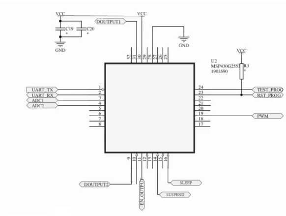
4.3 MSP430G2553 I/O Pins . . . 29
4.4 ANT nRF24AP2 I/O Pins . . . 31
4.5 DRV8601 Haptic Driver I/O Pins . . . 31
4.6 Connectors and LEDs . . . 32
4.7 Communication Packet Flow Between Hardware toolkit and Mobile Phone . . . 37
4.8 Earl Broadcast Message Structure . . . 38
4.9 Sony Ericsson Xperia Active . . . 39
4.10 Hardware Toolkits Connection Example . . . 41
4.11 Hardware Toolkits Connection Example with Web Services Connection . . . 42
4.12 Information Pushing . . . 43
4.13 Information Request from Web Server . . . 44
4.14 Monitoring Sensor Data from Web Server . . . 44
4.15 Controlling Actuator Connected to Hardware Toolkit from Web Server . . . 44
4.16 Current Consumption Measurement Setup . . . 45
4.17 Current Consumption Measurement for Receiving Mode . . . 46
4.18 Current Consumption Measurement for Transmit Mode . . . 47
4.19 Current Consumption Measurement for Shared Channel Slave Mode . . . 48
4.20 Force Sensor . . . 50
4.21 Current Consumption Measurement for Sensing Mode . . . 50
4.22 Haptic Actuator . . . 52
4.23 Haptic Driver Test - Current Consumption . . . 52
4.24 Average Power Consumption Results . . . 56
4.25 Earl Hardware Toolkit Communication Latency . . . 57
4.26 Experiment Results for Communication Between Mobile Phone and EWS . . . 59
List of Tables
3.1 Hardware Toolkit Requirements . . . 14
3.2 Earl Metrics . . . 16
3.3 Requirements for Software of Hardware Toolkit . . . 16
3.4 Metrics for Software of Hardware Toolkit . . . 17
3.5 Earl Mobile Platform Requirements . . . 18
3.6 Mobile Platform Metrics . . . 18
3.7 Earl Web Platform Requirements . . . 18
3.8 Earl Web Services Metrics . . . 19
3.9 Bluetooth Classes with Maximum Permitted Power . . . 19
3.10 ANT AP2 Power States @3.3 Supply Volt when 32KHz External Oscillator Used . . . 23
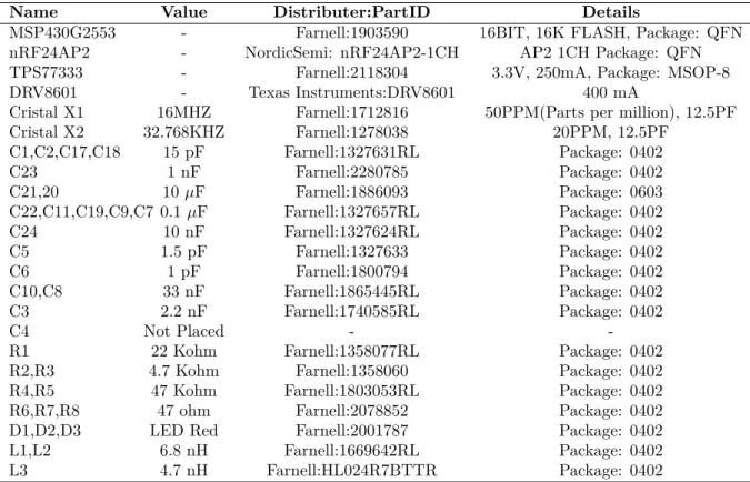
4.1 Parts used in Earl hardware toolkit . . . 28
4.2 Earl Hardware Toolkit Channel Configuration . . . 37
4.3 Earl Hardware Toolkit Channel Configuration . . . 40
4.4 Earl Hardware Toolkit Mobile Phone Connection Example Device Parameters . . . 41
4.5 EWS Web Server Specifications . . . 42
4.6 Force Sensor Specifications . . . 49
4.7 Haptic Vibrator Specifications . . . 51
4.8 Haptic Driver Test Inputs and Current Consumptions . . . 52
4.9 Hardware Toolkit Peak Power Consumption Results . . . 54
4.10 Hardware Toolkit Average Power Consumption Results . . . 55
4.11 Mobile Phone and Web Server Latency Test . . . 58
Abstract
Proof of concept systems are the significant examples of technology designs to test and analyze tech-nology ideas. Toolkits enable techtech-nology developers to decrease the complexity and time to create draft designs with many iterations. Toolkits with combinations of sensors and actuators may lead technology designers to new design spaces and opportunities by decreasing design difficulties.
This thesis proposes a new wireless toolkit, called Earl, for beginner level technology designers. With-out being experienced on engineering skills Earl allows technology designers to create proof of concept systems in shorter time than implementing the system from scratch. For experiencing with sensors and actuators, this toolkit has a vision to design plug and experience systems. By using Earl, designers can connect analog actuators and sensors by plugging them to toolkit. Additionally, Earl is designed to in-crease the experience time by lowering the power consumption as much as possible. Therefore, application developers can use Earl portably in long term experiments. Furthermore, Earl is designed in Internet of Things concept. By using Earl web services, technology designer can access the data sent from the sensors and can control the actuators connected to hardware toolkit from a web browser.
Earl hardware toolkit aims to provide long experiment time as much as possible. This is why, Earl hardware toolkit is designed to lower the power consumption if hardware toolkit is not actively handling processes. In sensing only mode, technology developers can use Earl hardware toolkit more than 1 month without recharging the toolkit battery. Using actuators in application may change power consumption of the hardware toolkit. Therefore, applications with actuators may have lower experiment time.
Acknowledgements
First of all, I would like to thank to my supervisor, Prof. Mark Smith for his invaluable support in every stage of this thesis work. I learned a lot from his experiences, but, maybe the most important one is he showed me how to think analytically about real life problems.
Secondly, I also would like to thank to all Mobile Life Centre and Swedish Institute of Computer Science (SICS) researchers, especially Prof. Kristina H¨o¨ok, Petra Sundstr¨om, and Jordi Solsona, for their contributions and providing me fantastic opportunities.
Finally, I am very greateful to my family and my love, Ece Mandiracioglu, for their endless support on any single moment of my life. It would not be possible without them.
Chapter 1
Introduction
Prototyping is a significant activity of technology development that helps developers shape the technology design. Technology developers can experience and get inspired by draft designs, discover innovative solutions and produce better technology by iterations. This is why, design concepts may assist technology designers to improve the technology implemented. Prototypes are working examples of a technology that enables developers to test and analyse ideas. Technology developers may develop or improve prototypes by using a system, which can facilitate designers’ effort as well as shortening design time for development and prototyping [1]. These kinds of systems are called toolkits. They are composed of both hardware and software modules allowing application developers to design, test and break down the implemented technology.
Technology developers use sensors to sense the environment where the sensors are placed and use actuators to have the ability to react to changes in that environment. Combinations of sensing and actuating systems enable technology developers to create variety of applications for technology designs. This is why, toolkits lead to new design spaces and opportunities for developers by enabling technology developers to test design ideas with sensors and actuators easily and without dealing with complexities. Mobility is a feature which is getting popular in toolkit applications. In mobile systems, mobile devices can function in a certain distance without cable limitations. For some applications, mobility is a desired requirement. For instance, in human body related applications, position of a toolkit in 3D space may change time to time. In this case, cables may get broken or limit the movement of the toolkit. This is why, developers prefer to use wireless communication between the connection points to move freely without cable limitations. However, mobile devices have limitations with battery lifetime. Wireless communication is a more power consuming technology than wired communication. Moreover, wireless communication may affect the application quality in terms of communication speed and communication range.
Developers have been using mobile toolkits for development and testing especially for early design stages [2]. In the beginning of technology development stages, developers examine many ideas and implement draft solutions for existing problems by using toolkits. The goal of this thesis is to introduce a wireless toolkit that helps technology developers to experiment with most common analog sensors and actuators in a rapid way and without dealing with implementation complexities. In order to increase experiment time with this toolkit, it is intended to decrease power consumption of the toolkit as much as possible. To help to decrease the power consumption, low power technologies are used. By using low power and wireless features1, technology developers can create portable systems with longer battery
life. In the coming two sections, I will talk about benefits of low power technologies and role of wireless technology. Then, I will explain concept of “always connected” devices and advantages of merging systems with Internet applications. Finally, I will introduce Earl Toolkit and explain how Earl is working.
1In the Section 3.4.2 and Section 3.4, low power technologies are explained in details and compared with other
technolo-gies.
CHAPTER 1. INTRODUCTION 2
1.1
Low Power Technologies
Low power technologies have a variety of benefits for mobile toolkits. First of all, low power consumption supplies longer battery life. Especially mobile toolkit applications’ battery life is an important parameter for the experiment duration. For some mobile toolkit applications, testing may take a long time, thus application users can not test draft solutions properly without recharging the battery, which may conclude in wrong experiment results due to the interruption of the testing.
Secondly, low power technology decreases the application costs. Due to high heat generated in high power consumption systems, the system requires more complicated, thus costly, silicon structures. Fur-thermore, low power consumption decreases the cost since smaller battery supplies cost less.
Moreover, longer experience time with draft technology solutions, smaller size of toolkit, low cost of the proposed solution, and portability are desired requirements of mobile toolkits used in the early design processes. This is why, low power consumption is a targeted characteristic of mobile toolkits.
1.2
Role of Wireless Technology
Wireless communication has great opportunities. However, it has some drawbacks as well. In this section, first I will compare wired and wireless communication. Then, I will explain why I used wireless communication technology which is a desired featured of toolkits.
Firstly, wired connection has less power consumption in compare to wireless solutions. Most wireless technologies requires extra modules, components or peripherals such as antenna circuit and technology related Integrated Circuits (IC) instead of single wire. This is why, wired solutions are cheaper solutions. Security is another significant challenge for wireless systems. Most wireless technologies have vulnera-bilities, such as unauthorized access or damage to wireless devices using wireless network. If the exchanged information has high confidentiality, wireless communication should be secure enough to operate. On the other hand, wire communication is isolated from its ecosystem. Therefore, wired communication is much safer than wireless solutions.
Wired communications are more reliable communication compare to wireless connections in terms of communication interference. There are shielded cables available to prevent interference by noisy ma-chineries. For instance electric motors may interfere wireless communication devices. This is why, wired communication is less problematic in terms of interference. However, wireless communications may inter-fered with other wireless networks which are operating in the same frequency range. Physical conditions such as temperature, environment permeability and acoustics also effects wireless communication quality. Because of these reasons, exchanged information can be corrupted during the wireless transmission. This may cause delay or miscommunication in wireless connection.
In computer networking, bandwidth term is used for consumed information resources in bits per second for communication. Wireless communication has limitations in terms of bandwidth whereas wired communication has much higher bandwidth limits. Wireless transmission speed depends on the technology implemented. Used modulation techniques and methods directly affect the communication quality[3]. Physical and environmental conditions, for example electromagnetic waves generated from other devices, interfere wireless communication. Microwave ovens, which use radio waves to heat food, interfere most commercial wireless communication since they are both working at commercial 2.4 GHz operational frequency range. On the other side, wired communication speed depends on quality and material, length and size, and shield of cable.
Mobile devices exchange information between two or more devices that are not connected by a wire. Portability and communication access in limited regions, enable greater flexibility and mobility for ap-plication users. Technology users can relocate the communication devices without the additional cost of rewiring and excessive downtime while moving. Toolkit users prefer to use wireless communication in applications where relocation of toolkit is possible.
Short distance wireless communication may be useful where physical connection is not available be-tween the connection points. Wireless communication is mostly used in cases where the communication device has to be able to communicate with other devices without cable limitations. Therefore, portable devices can communicate with each other in a certain range where wireless communication technology operates.
CHAPTER 1. INTRODUCTION 3
Another benefit of wireless technology is having less cables around portable devices. Many technol-ogy developers don’t like junk of cables, because cables prevent the device to change design aesthetics. Moreover, in applications where a portable device is attached to human body, wires may prevent human body to move naturally. Thus, wires may change human behavior while application user is experiment-ing which may lead to false results. Since technology development market has need of portable devices, wireless communication technologies are available for near field applications.
Until recently, most sensor and actuator based applications have been using wires or logging systems to transfer information or obtain data from a sensor node to application users. In the past, wireless communication was also available to exchange information between mobile devices. However, amount of power consumption was limiting the battery life; therefore, application developers could not use wireless mobile systems in the long run.
The ultra low power technologies mainly serve the need of targeted device to operate for longer time durations. There are ultra low power wireless communication technologies available in the market for near field communication. In low power wireless communication technologies, communication range can be dependent on many factors; such as wireless communication operation frequency, antenna type, antenna power, antenna length, environment, communication protocol and many more. Currently in the market, most near field communication range for ultra low power technologies vary from couple of centimeters up to order of 10 meters. Technology designers should consider wireless communication range according to specifications of the application.
To sum up, wireless communication may be more advantageous than wired communication. In the early design phase, developers can create working proof of concepts of intended application by using toolkits. If this toolkit has a low power wireless communication module, toolkit users can create working proof of concepts rapidly and can exchange information with other devices in a close range without cable limitations.
1.3
Internet of Things
While technology is advancing in great number of fields, wired and wireless networks are enclosing around us. Innovations in technology create a new trend in Internet world that is called “always connected”[4] concept. New Internet technologies such as IPv6[5] and push notification[6] allow for instant communi-cation and unique Internet addresses for technology devices.
A concept, in where physical objects becomes part of the Internet, is called Internet of Things (IoT)[7]. IoT concept enables physical objects to be accessible through the network, therefore information like status, position, and location of physical objects are part of Internet services and intelligence of physical things [4]. Linking physical objects to Internet Network enables experiencing with everyday objects in personal and social environments.
Toolkits for rapid developments empower technology experiences by adding short range mobile commu-nication in IoT concept. Technology developers can explore new ideas by adding wide range of additional gadgets[8] and everyday items. Therefore, developers link people and digital design materials by using mobile communication in anytime and anyplace.
First concept in IoT is designed for object tagging [4] however, then the IoT concept became more colorful with sensors and actuators. After International Telecommunication Union’s first announced report in 2005 [4], the aim of IoT was taken the current shape. New dimensions with sensors and actuators will be approachable from anytime, any place with connectivity for anyone. This means that real objects could be connected to each other. Moreover, connections will multiply and create an entirely new dynamic network of networks.
Cellular phones became light-weighted, more skilled and part of the Internet network. Many companies focused on interactive products so that technology users started to open a space for these devices in their life. All these changes consequenced to boom in Internet of Things world. In the last years, there are important milestones in silicon based technologies. As a consequence of price fall of the transistors for the last ten years, silicon vendors have started to produce low cost and high performance new technologies; such as Bluetooth[9], ZigBee[10], and ANT[11]. With the help of enhanced technology, new wireless solutions and communication protocols are introduced. Internet can become a more social and commercial platform than before by connecting everyday objects with our lives. Wireless connection may be a more
CHAPTER 1. INTRODUCTION 4
proper solution to connecting all everyday objects in IoT concept by removing cable limitation. By using IPv6, connecting 50 billion different objects together is possible on the Internet network[12].
Accelerated developments in an interactive digitalized world have led to an increase in the interest of sensing and actuating experiences with the concept of IoT. Designing interactive platforms with the environments that are supported by hardware, software and applications are complicated processes. Difficulties in designing digital material, such as sensors and actuators, and material properties make harder to examine the interaction between the environment and the digitalized material. Rapid growth of technological opportunities may improve, limit or help design processes. Thus, technology developers can get experienced and inspired by digitalized material such as sensors and actuators by the help of toolkits.
1.4
Internet Services with IoT Vision
IoT concept systems have a vision to distribute work balance to all connection nodes in the network. IoT comprises of four major concepts [13]: distributed computing, distributed information processing, basic wireless networking and automatic identification. Every device in IoT vision has a network connection and a service provided by Internet. According to Kuniavsky [13], IoT’s vision is, instead of just connecting devices over a network, creating new experiences according to developers’ interests by using Internet services. Internet services add values to users by having more interactive experiences; such as well connected ecosystems and information exchange between connection points.
Technology designers can connect different Internet services and applications to explore different ideas. IoT concept enables technology developers to convert technology devices into tools that technology users get the Internet services. Therefore, technology devices can get a shape according to Internet services [13]. Using combination of Internet services provided by a back hand supporter such as a cloud system[14], enables developers to experience technology immediately with the possible combination of inexpensive things. Therefore, it is a profound change that physical actions can transform into knowledge rapidly on the cloud system by the help of IoT vision. Through this vision, deploying ubiquitous wireless systems and spreading information processing enable technology developers to create enormous number of applications.
1.5
Earl Toolkit
Power consumption is a limiting factor for mobile devices in terms of being portable. This is why, I took the approach of decreasing power consumption of the toolkit for the sake of increasing the time of use. Furthermore, I also aimed to exchange information via wireless technologies for portability. In this thesis, I will focus on short range communication with low power facilities. Therefore, I implemented a portable wireless toolkit that exchanges information with mobile devices in a short range. By the help of this toolkit, technology developers can experience with most common analog sensors and actuators for a longer time than other near field communication technologies without cable limitations. This system also enables developers to create quick implementation of small systems without dealing with embedded software development challenges.
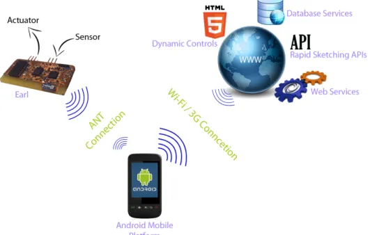
In this thesis, I proposed a solution which is a hardware and software toolkit. Designed system can be divided into 3 main parts. First part is Earl, a wireless mobile device that technology developers can rapidly connect to and experience with analog sensors and actuators. Second part is a web platform. Earl can not only communicate with other Earls but also can exchange information with a web platform. Web platform is used both for storing the data received from Earl and for controlling Earl itself. Last part is Android [15] mobile phone which is used as a connection bridge between Earl mobile devices and Web Services. Figure 1.1 shows the general system layout for Earl toolkit.
Most early design toolkits help technology developers to create systems to prove the concept by programming microprocessors or micro controllers. However, designing an embedded system application may require embedded systems knowledge and software coding skills. Therefore, developers may have limitations to create a system. In most applications that sensors control actuators, developers should write applications for the embedded device. However, Earl helps developers to obtain analog sensor data and control actuators by a web interface or an Android mobile application without writing embedded software
CHAPTER 1. INTRODUCTION 5
Figure 1.1: Earl System Layout
code. Therefore, developers will not have to deal with hardware system design and low level embedded programming. Thanks to Earl, technology developers can implement small example applications rapidly without dealing with complexities. Earl not only decreases early design development process but also enables technology developers to focus on interaction with idea instead of technical implementation. For example, let’s consider a technology developer who wants to experience with a balloon. She intends to measure the pressure inside the balloon. According to how much pressure inside the balloon, vibration on a vibrator is adjusted. Normally, measuring the pressure inside a balloon without using a supportive system takes an effort. Even more, if the technology developer has no engineering background, it may take too much time and effort to design, test and experience with a system. Earl toolkit enable technology developers to implement small systems as like this experiment. In order to implement this experiment with Earl, application developer should connect an analog pressure sensor and a vibrator to Earl. Next, technology developer should set input pressure sensor to control the output vibrator on Android mobile application. Finally, application developer should connect a battery to Earl, place the Earl into balloon and start the experiment on Android application. In this way, application developer can experiment with a balloon and a vibrator rapidly without need of writing embedded software code.
Developers can create web applications that can exchange information with Earl system. In addition, developers can create systems that can communicate with multiple Earl toolkits through web platforms in IoT concept. Therefore, by controlling one or multiple sensors, developers can experience with one or multiple actuators through Internet communication. By the help of Internet communication, developers can collect information and control environment in different locations.
This thesis report is dedicated to proposing the Earl toolkit as an alternative system for technology developers to create rapid sensor and actuator applications that developers does not have to deal with low level engineering difficulties in the early design processes. The rest of this report is organised as follows: Chapter 2 explains what a toolkit is and why it is a useful device for early design processes. Moreover, Chapter 2 introduces and compares some toolkits that technology developers are using to create prototypes and proof of concepts with their benefits and drawbacks in terms of low power consumption, wireless communication and ease of use. Chapter 3 explain goals of design, requirements, main units
CHAPTER 1. INTRODUCTION 6
and technologies used in the development of Earl Toolkit. Chapter 4 explains implementation of Earl hardware toolkit. Chapter 4 explains Android mobile platform that supports the Earl toolkits to connect to Internet. Web services platform, which enables application developers to connect their applications to web applications, is also explained in Chapter 4. In the end, Chapter 5 draws the conclusion and suggests possible future works about Earl toolkit project.
Chapter 2
Background Work
2.1
Need of a toolkit
2.1.1
What is a Toolkit
Technology designers create draft designs in order to get experienced and inspired. The produced draft design in the early design stages is called prototype. Prototypes are the significant proofs of a design to test and analyze ideas. During the design process, technology designer discovers innovative solutions and produces better technology by many iterations. The repetitive process of refining the design may take quite a long time and much effort. That is why, technology developers get help from development aid systems. A system which helps to develop or improve prototypes with less effort is called a toolkit.
As part of a product development process, designers create examples of the early stage conceptual approaches in order to experience how a product might work, rather than creating fully functional systems. While technology developers are implementing complicated systems, first they design small sub systems and later they merge small systems together. In this way, technology developers first experience with small systems then add complicated functions and details later. That is why, technology draft designs are supposed to be lightweight, user-centered, agile and focused on users’ experiences initially in order to explore new ideas without technologic limitations and complexities[16]. In the next stage of early design, designers merge satisfied draft designs and design as a proof of concept, named prototype. During all these phases, toolkits play significant roles in shaping the design by simplifying complexities, supplying pre-designed modules, and showing example applications.
There are many toolkits available for different application purposes. Technology developers should select a toolkit based on the application requirements. In this thesis, I focused on toolkits which aid designers to monitor the changes in toolkit’s environment by sensors and react toolkit’s environment by actuators. Designers can use this kind of toolkits to create intelligent everyday objects by attaching toolkits to them. For example, designers can use toolkits to understand the change of temperature on the table surface or acceleration of a soccer ball. In an early design process, technology developers can create a rapid proof of concepts by using toolkits instead of implementing the whole design from scratch. Therefore, by using toolkits, technology developers can experience with draft designs without dealing with complicated details.
Toolkits are used to help developers to consume less time and effort during the design process. Many toolkits are combined with hardware and software for supporting designers to provide ease of use. Hard-ware toolkits may provide jacks or clips to connect sensors and actuators to the toolkit. Thus, designers can test and experience small systems without soldering peripherals. Some toolkits come with default modules to decrease implementation time. By using default modules, developers don’t need to make an effort for implementing all parts of a desired system. Software toolkits may provide easy code de-velopment, better code readability, code compatibility with multiple hardware devices, and rapid design implementation. By using software toolkits, developers can reduce the complexities during the design process and don’t have to deal with low level software design.
CHAPTER 2. BACKGROUND WORK 8
2.1.2
Sketching and Prototyping
Sketches and prototypes are both core components of design processes [16]. However, they are used in different phases of the design processes. Sketching is an activity to project abstract ideas into draft designs in order to experiment with the ideas. Designers create sketches to obtain better designs during early design processes. These sketches can be small systems that demonstrate how designers’ ideas work. Designers implement physical designs of their ideas. This physical designs are called sketches. These sketches can be get shaped after iterations to form a proposed solution. These proposed solutions are called prototypes.
Sketches are dominantly used in early design processes because of cost efficiency, timeliness, quantity, and disposability. Prototypes are formed by many iterations of sketching. This is why, sketches take less time and are cheaper. Sketches have less property than prototypes because sketches are subset formed ideas of prototypes. Furthermore, designers create sketches to be influenced from draft designs. Thus, designers use sketches to explore new concepts and form the prototypes.
Prototypes are more comprehensive instantiations than sketches since they contain many ideas and cost more than sketches. Sketches are faster ways to experience ideas. Technology developers spend less time to create a sketch. Moreover, designer can produce many samples of sketches with less cost and in more quantities. In addition to this, a technology developer can restore the sketch easily, sketches have lower complexity than prototypes. Prototypes may not exactly resemble the design ideas in the technology development process, but sketching is a significant process in the technology design procedure because of its contributions to development.
Basically, we can compare sketches with prototypes in the following terms [16]:
• Sketches are imitative instantiations of design ideas. However, prototypes are functional instantia-tions of design ideas.
• Sketches may suggest new arguments to technology designers, while prototypes describe function-ality.
• Technology designers create sketches for exploring new ideas and concepts. However, prototypes are refined forms of ideas and concepts.
• Sketches propose a potential solution to a question. On the other hand, developers use prototypes to test a concept.
• Sketches are tentative instantiations of a concept. Therefore, they provoke designer to create different concepts. However, prototypes are more specific designs than sketches. Thus, technology developers create more detailed concepts by using prototypes.
2.1.2.1 Sketching in Hardware and Software
In the early stage of technology design process of ideation and iteration, technology designers explore different solutions after many iterations [17, 18]. Designers are looking for feasible and desired solution for the technology design, whereas developers use hardware and software as design materials to create sketches[19]. However, it may be difficult for designers to expose and experience with design material to understand the technology [19].
To take an advantage of a design material, technology developers might improve hardware and software in innovative ways [19]. In order to create a possible, desired and acceptable idea by using a digital design material, technology designers should form hardware and software sketches for imitative instantiations of the desired concept. That is why, technology developers use toolkits to create a small system rapidly in order to experience with design materials.
Using digital design material such as sensors and actuators supported with software may require deep knowledge of engineering and high programming abilities. Difficulties in technical skills may limit the technology developers. That is why, a toolkit for sketching in hardware and software should be user friendly to designers who does not have technical background on digital design materials.
CHAPTER 2. BACKGROUND WORK 9
2.1.2.2 Do It Yourself Technology
Most available toolkits are used by the technology developers who want to create the whole system from scratch. Application developers may consider building, modifying and fixing the developed draft systems without using predesigned systems. Developers, who are producing the technological designs without using almost any kind of pre-assembled parts, called Do It Yourself (DIY) developers [2]. Therefore, iterations for sketching and prototyping became slow and expensive. Instead of developing every small detail in a draft system for early design process, application developers should use pre-made parts, modules, and software libraries to experience the technology as soon as possible. Although, technology developers will be limited with non-customized systems, sketches will be working conceptually with low cost in a short time period.
Although, DIY designs may have higher performance since they are designed for a customised project instead of a general purpose, they take designs takes more effort and time; moreover, finding mediums cost as well [2]. This is why, application developers should select pre-made systems, modules and libraries which are compatible with the toolkits in their sketching.
Today, technology designers can use different toolkits to speed up early design processes. In the following chapter, most commonly used early design toolkits will be compared with Earl toolkit in terms of power consumption, mobility and ease of use.
2.2
Current Toolkits
Currently, there are many hardware and software toolkits that assist technology designers to explore new ideas and experience new concepts. In this section, most commonly used toolkits for sketching and prototyping will be discussed in terms of power consumption, mobility, and ease of use.
2.2.1
Arduino
Arduino[20] is one of the most popular sketching and prototyping toolkit for technology developers [21]. Arduino is an open-source platform that lets technology designer to build standalone controllers with or without a PC connection. Developers can select specific Arduino boards according to the application. For example, there are Arduino boards available for sensor applications, actuator applications, wearables and textile applications, and wireless communication related applications and more.
Arduino boards have input and output pins that enable developers to connect external peripherals and modules. Technology developers can find compatible sensors and actuators, modules and peripherals according to developer’s specific applications on commercial web sites such as SparkFun [22]. On web sites like Sparkfun, designers can find variety of sensors and actuators that are compatible with Arduino. Developers can connect analog and digital sensors to Arduino board and experience it by the example code supported by Arduino’s web site. Arduino also supports many actuators such as different kinds of motors, vibrators, and speakers.
Arduino is supported by multi-operating systems on PC and Unix computers. Technology developers can test their applications on most common operating systems such as Windows, Mac OS, and many Linux distributions. Arduino has pre-written libraries to support application developers. By the help of pre-defined functions and variables, technology designers may not have to use too much low level programming compared to PIC[23] programming.
Arduino boards have 16-bit and 32-bit Atmel[24] microcontrollers. More processing power needed applications can be implemented on 32-bit Atmel processors. For example, Arduino Due has 32-bit Atmel CPU based on ARM’s [25] Cortex M3 Architecture[26] which is operating at 84 MHz. On the other hand, some Arduino boards are designed for low power consuming applications such as battery critical applications.
Power consumption is a matter of design issue for Ardunio application developers. For mobile proto-typing and sketching, designers should consider power consumption in order to increase battery lifetime, thus application experience time. Most Arduino boards are designed for cable powered applications. This is why, for stable or power cable limited applications developers don’t have to consider low power consuming modules. On the other side, for mobile applications, developers should consider less power
CHAPTER 2. BACKGROUND WORK 10
consuming peripherals and boards, bigger battery size, and software oriented power optimisation modes such as sleep mode.
According to my experiments one of Arduino’s basic level boards, Arduino Uno consumes 47 mA current by applying 9 Volt input voltage to board. Arduino board programmed as doing nothing and having an empty while loop. My setup to measure power consumption of Arduino is as follows: I connected Sinometer MY-68 Multimeter [27] to 9 Volt DC supply and Arduino Uno board serially. On the current reading mode, I measured current consumption of Arduino Uno board. By using equations on 5, I calculated power consumption of Arduino board as 0.423 Watt. According to Arduino’s specifications, Arduino Uno board can consume current up to 500 mA operating on 9 Volt, thus 4.5 Watt power consumption[28].
Some Arduino kits have available pins to connect wireless modules such as Wi-Fi and Bluetooth mod-ules to Arduino boards. Therefore, developers can exchange information wirelessly in their applications. In order to connect wireless module to an Arduino board, developers should connect module’s output and input pins to Arduino’s general purpose input and output pins. Then, application developer can download module related source code from Arduino’s or module’s web site and load the code to Arduino board. Developers can change the code behaviour by editing the downloaded code from Arduino’s web site. Furthermore, developers can connect multiple modules and create more complicated systems by using Arduino toolkits. However, developers have to know how to connect modules to Arduino boards and program Arduino boards by sample code provided on Arduino web site. Some technology developers may have difficulties to create wireless application because of lack of knowledge and practical experiences. In this case, developers can get help from Arduino’s forum web site[29].
Arduino is a toolkit for developers who has a background on electronics and programming. However, freshman developers also can implement small systems by doing tutorials on web site. Connecting pe-ripherals and communicating with connected pepe-ripherals are much easier by using Arduino’s supported software framework. Developers who want to have long experiences with Arduino in mobile applications, should consider lower power consumption Arduino boards since power consumption of Arduino boards are high relatively to other toolkit solutions such as mBed[30].
2.2.2
mBed
mBed[31] is an online platform for rapid prototyping system with micro controller-based systems. It has a 32-bit ARM main processing unit, which is powerful enough for many applications such as sensor and actuator based applications, signal and sound processing applications, and motor control applications. mBed is a breadboard attachable board with many digital and analog inputs. Technology designers can attach analog and digital sensors to mBed boards. Additionally, analog pin outputs are also available to control most actuators.
mBed has a web site [30] that contains software development platform for prototyping applications. In this web site, developers can write software by using the supplied software framework and test with mBed’s prototyping boards. Currently mBed has 2 board selection with different ARM processors. mBed NXP LPC11U24 is for prototyping USB (Universal Serial Bus) Devices and battery powered mobile applications. mBed NXP LPC1768 is more convenient for prototyping Ethernet, USB Host Devices applications, and power needed applications. Both boards have different processor models and soldered components on the board therefore power consumption of boards are different.
LPC1768 board does not consuming less power than Arduino Uno board. According to my experiments I calculated LPC1768 board consumes 141 mA when it is working on 5 Volt which is supplied by a USB connector. In order to measure the current consumption I followed the same path as I did for Arduino Uno board. I programmed LPC1768 board for an empty while loop therefore board was not doing any process. According to my experiment I calculated power consumption as 0.705 Watt by using Equation 5.2. LPC1768 board supports Ethernet connections. However, Ethernet module on board consumes so much power. In this experiment, I turned off Ethernet features. On the other hand, when I did the same experiment with Ethernet features enabled, I measured 256 mA current consumption while LPC1768 is supplied with 5 Volts. Therefore, power consumption is calculated as 1.28 Watt according Equation 5.2 given in Section 5. On the other side, mBed has another low power prototyping board called LPC11U24. According to specifications given in mBed’s web site [32] LPC11U24 may consume 16 mA with 3.3 supply voltage.
CHAPTER 2. BACKGROUND WORK 11
LPC1768 is a board for power required applications such as motor control and ethernet communica-tion applicacommunica-tions. On the other hand, LPC11U24 is a less power consuming board than LPC1768 board such that application developers can use LPC11U24 board on mobile and low power required applica-tions. There are many wireless applications examples available for LPC11U24 board on mBed’s web site. Technology developers can create small systems with low power wireless communication technologies by using this board.
As an example, technology designers can create small applications by obtaining a wireless commu-nication module, sensors and actuators that are compatible with LPC11U24. Most compatible modules are listed on the board software library. Designers can use examples and sample codes on the web site to setup test environments for design concepts. However, in order to design complicated systems, mBed requires technical background for developers. To sum up, mBed is a toolkit for engineers to create small systems easily by using prewritten libraries and sample codes. LPC11U24 board enables designers to implement mobile and battery powered applications with long battery life compare to LPC1768 board.
2.2.3
Other Toolkits
Modkit is a toolkit for developers who have beginner level engineering skills [33]. It has visual block dia-gram interface for developers who prodia-gram popular hardware toolkits such as Arduino. By using Modkit, designers can implement basic sensor and actuator applications without writing software code. Modkit is a web application that enables developers to draw graphical structures for basic coding functions such as loops, variable assignment, and fetching data from a peripheral. Technology designers can read sensor data from sensors and control actuators by designing boxes. Designers who has no coding background can create small applications without knowing software coding. Furthermore, technology designers can see designed code in code view perspective of Modkit. Developers who have technical background can edit the code and reshape designed structure for complex algorithms.
On the other side, Modkit does not help application developers to lower power consumption and mobility. Developers who has programming skills can implement mobile communication features on code view perspective. However, Modkit is not a powerful toolkit for designers who wants to create rapid mobile systems by lowering the power consumption.
Wiring is an open-source development platform for Wiring boards that developers can control attached peripherals to Wiring toolkit[34]. Wiring has special supportive libraries that makes easier to program Wiring microcontrolers. It helps developers to increase code readability and decrease code complexity. Developers can connect analog and digital sensors and actuators to Wiring toolkit. By the help of Wiring software development platform, developers can exchange information with sensors and actuators without writing low level software code. Designers can also connect Wiring to a computer by using a USB cable. Wiring software toolkit supports sending and receiving information through a computer. Thus, developers can merge small systems that they designed with computer applications.
Little Bits is a very simple but powerful toolkit for sketching [35]. Application developers can merge small magnet modules to create simple but effective systems. However, all used modules in Little Bits are analog and they are not re-configurable. In addition to this, application developers can only experience with sensors and actuators supported by Little Bits.
Makey Makey [36] is a toolkit that designers can connect daily object to Makey Makey toolkit and control computer applications. Furthermore, developers can also control popular toolkit platforms such as Arduino. Makey Makey has ability to control basic keyboard buttons such as arrows and control buttons. Developers can control a PC application by pressing pre-assigned buttons on Makey Makey toolkit. For example, developers can use a banana to control a key on computer keyboard by using Makey Makey. By using Makey Makey, technology developers can create rapid systems without dealing with technical complexities.
In this chapter, I introduced what a toolkit is and why it is playing a significant role in an early design stage of technology development. Then, I presented most commonly used toolkits that designers are using for creating small systems. In the next chapter, I will talk about objectives and requirements of Earl toolkit. Furthermore, I will also explain main units and technologies used for Earl toolkit.
Chapter 3
Earl: Toolkit for Sketching
In this chapter, first I will describe what the whole system ideally should be. Secondly, I will describe goals and vision of this toolkit. Next, I will explain requirements for the design and metrics of the toolkit. In the end, I will explain how I selected wireless communication technology and low power microcontroller unit for Earl toolkit.
3.1
System Description
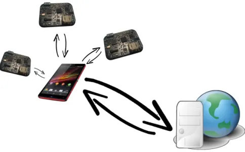
Earl is a toolkit that application designers can create proof of concept systems faster than implementing the system from scratch. In these systems, Earl enables technology developers to use analog sensors and actuators. One of the significant benefit of Earl toolkit is developers can connect sensors and actuators to Earl toolkit without soldering or wiring. In Earl toolkit, developers can exchange information between Earl toolkit and Earl web services through Internet. In order to connect Earl to Earl web services over Internet, Earl connects to an Android mobile phone wirelessly and then the mobile phone takes care of the data exchange between mobile phone and web services.
Earl is a mobile toolkit and it is working with a battery. This is why, technology designer can move Earl freely without cable limitations. Earl is designed to take advantage of low power technologies. Therefore, application designers can use Earl toolkit in long term experiments without re-charging or changing the battery.
In this thesis, I proposed a solution which is hardware and software toolkit. Designed system can be divided into 3 main parts. First part is Earl, a wireless mobile device that technology developers can rapidly connect to and experience analog sensors and actuators. Second part is a web platform. Earl can not only communicate with other Earls but also can exchange information with a web platform. Web platform is used both for storing the data received from Earl and for controlling Earl itself. Last part is Android mobile phone which is used as a connection bridge between Earl mobile devices and Web Services. Following Figure 3.1 demonstrates the system Earl Toolkit and its supportive systems, which are Android mobile phone and web services.
3.2
Design Objectives
This section explains target goals of the toolkit design. In the beginning of the project, I investigated possible toolkits that designers can use in an early design stage of technology development. These toolkits are described in Chapter 2.2. Based on these toolkits, I collected the requirements of a toolkit using which designers can create proof of concept systems. Among all toolkit requirements, I focused on those of sketching toolkits that designers can implement sensor and actuator applications.
The project’s design objectives to decide the requirements are as below:
• (DO1) Toolkit for sketching in hardware and software (TSHS) enables technology designer to create sketches faster than implementing by designing from the scratch. Most designers use toolkits instead of implementing the whole design from scratch. However, developers who have enough knowledge can create DIY systems. These systems can be much expensive and take more time than
CHAPTER 3. EARL: TOOLKIT FOR SKETCHING 13
Figure 3.1: Earl Hardware Toolkit Communication With Earl Web Services
implementing the system with a toolkit. This is why, technology developers use toolkits and ready made systems to experience with design implementation rapidly such as Arduino and mBed. • (DO2) TSHS enables application developers to create sketches in order to experience with sensors
and actuators. Most toolkits support digital and analog inputs and outputs. By using inputs and outputs developers can connect sensors and actuators. Some toolkit boards can be more customized according to the application type. For example, most Arduino boards have analog to digital converters. Therefore, application developers can connect analog sensors to the application board and process the sensor data. Furthermore, some toolkits such as mBed’s LPC1768 board has analog output that developers can directly connect this output to control analog actuators. • (DO3) TSHS can be used for small experiments in order to get influenced from the sketches. Most
toolkits that I have introduced are used for prototyping such as Arduino and mBed. These toolkits are designed to build refined forms of ideas and concepts. However, sketching toolkits are more focused to explore ideas and concepts by trying different design materials. For instance, Makey Makey enable designers to use many daily objects as preassigned keyboard buttons. Designer can try many idea and design concepts rapidly without writing software.
• (DO4) TSHS has enough battery power that enables application user to experience technology for enough time. TSHS can be used for long term experiments that takes hours or couple of days without needing to charge or change the battery. Most toolkits introduced in Chapter 2.2 are designed for stationary applications. Therefore, power consumption is not a significant issue for these toolkits. On the other hand, developers may need toolkits that function for longer experiences. This is why, power consumption of a toolkit can be important parameter for application developers. • (DO5) TSHS is a light device that it is effortless to carry and attach anywhere. Designers may need small sized and lightweight toolkits especially if implemented design is a portable system. Some toolkits, such as Arduino Nano, have small size and customized for portable applications.
• (DO6) TSHS is a wireless toolkit that without cable limitations it can communicate with other devices. Developers prefer wireless communication and battery powered applications in order to design portable applications. Main vision for portable application is that mobile devices don’t have
CHAPTER 3. EARL: TOOLKIT FOR SKETCHING 14
cable limitations. Thus, they can move much easier. In addition to this, they can communicate with other devices, which support same communication technology, in a certain range. Many toolkits such as mBed and Arduino support wireless communication technologies for mobile applications. • (DO7) Technology designer can access the data sent from the sensor and can control the actuators
from a web browser. The TSHS allows the technology designer to merge the proof of concept design with different Internet services. Most toolkits are designed to handle the sensor and actuator data locally. However, by adding internet connection functionality to the toolkit, developers can exchange information through Internet.
3.3
Requirements
In this section, demanded requirements and specifications are given for the toolkit design. These re-quirements introduced below are proposed in order to fit the functionality of the toolkit. I will split requirements section according to main components of the system. These requirements are toolkit re-quirements, mobile application rere-quirements, and web service requirements. I will also divide toolkit requirements into hardware toolkit requirements and embedded software requirements.
3.3.1
Earl Toolkit Requirements
Earl toolkit consist of two main units: Hardware toolkit and embedded software which is designed for hardware toolkit. I will explain requirements below.
3.3.1.1 Hardware Requirements
Hardware toolkit is the device that designers can connect sensors and actuators, and can exchange information with this device wirelessly. To maximize the mobility, lower the power consumption, enable ease of use, I have defined requirements on Table 3.1 and according to defined requirements I have defined specifications on Table 3.2 for the design process.
Requirements Related Design Objective
• Earl is a mobile toolkit that is independent from stable power connection or wired communication with web services.
DO4, DO6, DO7
•Earl has small physical dimensions that can fit into technology designs effortlessly.
DO5 •Earl has a system that application
designers can try different technolo-gies without soldering or wiring.
DO1 • Earl has low power components
that enable target users to use it for long term experiences.
DO4 •Earl has a framework that its
func-tionalities can be controllable from distance
DO6 • Earl is a system that
technol-ogy developers can test most com-mon analog sensors and actuators rapidly.
DO2, DO3
CHAPTER 3. EARL: TOOLKIT FOR SKETCHING 15
Metric Value Units
• Minimum number of analog
sen-sors can be attached 1 Peripheral
• Minimum number of analog
actu-ators can be attached 1 Peripheral
•Maximum hardware toolkit device
dimensions (without battery) 3.5 × 2.5 × 0.5
cm3
• Toolkit battery life lasts with 150 mAh battery (1 Sensor only con-nected)
1 day
• Maximum Wireless
communica-tion range 10 meter
• Wireless ISM (Industrial, Scien-tific and Medical radio bands) band operation frequency
2.4 GHz
• Wireless Maximum Data Rate 2048 bps
• Maximum current consumption of hardware on Tx mode at 0 dB antenna power (1 analog sensor connected, 3.3 Operation Voltage, 1MHz, under normal conditions)
20 mA
• Maximum current consumption of hardware on Rx mode at 0 dB antenna power (1 analog sensor connected, 3.3 Operation Voltage, 1MHz, under normal conditions)
20 mA
• Battery type and number of cells Polymer Lithium Ion Battery 1 Cell
• Battery cells output voltage 3.7 V
• Min. battery capacity 150 mAh
• Hardware toolkit operation
volt-age 3.3 V
• System Master Clock Frequency 1 MHz
• Maximum current supply from power source under normal condi-tions
30 mA
• Maximum voltage dropout on
voltage regulator unit 200 mV
•Supply Voltage interval for
micro-controller 1.8-3.6 V
•Current consumption of microcon-troller on active mode at 1 MHz @ 2.2V
230 µA
•Current consumption of microcon-troller on standby mode at 1 MHz @ 2.2V
0.5 µA
•Current consumption of
microcon-troller on Off Mode at 1 MHz @ 2.2V 0.5
µA
•Number of pins of microcontroller 32 Pin
• Communication channels
sup-ported SPI,UART,I2C Communication Channels
•Number of minimum channel
sup-port for wireless communication 1 Channel
• Configurable periodic message
CHAPTER 3. EARL: TOOLKIT FOR SKETCHING 16
• Maximum Message
Re-ceive/Transmit Rate 32 Message Per Second
•Wireless operational frequency
in-terval 2400 - 2500 MHz
• Wireless operational frequency 2468 MHz
• Antenna output power 0, -6, -12, -18 dBm
• Antenna receiver power -85 dBm
• Analog to Digital Converter
(ADC) Bit Resolution 8, 10 Bit per sample
• Max ADC Sample rate 32 Sample Per Second
• Maximum A/D Conversion Time under normal conditions
<100 µs
•Maximum supported analog input
channel count 2 Analog Channel
• Maximum supported analog
out-put channel count 1 Analog Channel
Table 3.2: Earl Metrics
3.3.1.2 Embedded Software Requirements
Embedded software makes Earl a functional device. In the beginning of embedded software design, speci-fications are defined to determine the functionalities for a sketching toolkit. When I defined the embedded software requirements, I used the hardware toolkit requirements as base requirements of embedded soft-ware requirements. This is why, capabilities of embedded softsoft-ware depends on embedded hardsoft-ware. In embedded software design, I focused on functionalities such as mobility, low power consumption, and ease of use. Requirements for software design are listed below in the table 3.3.
Requirements Design Objective
•Earl is a toolkit that has mobile features to communicate with Android devices which are ANT enabled. There should not need a coding effort to establish a communication between hardware toolkit and mobile phone.
DO6 • Earl has a software that can control assembled components on the hardware
toolkit. DO2, DO6
• Embedded software of Earl has adaptable interface to exchange information with most common analog sensors and actuators at the same time. Users should not design an embedded software to control the sensors and actuators.
DO2 • Earl software framework has low power modes in order to decrease power
consumption. DO4
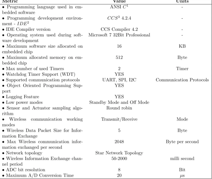
Table 3.3: Requirements for Software of Hardware Toolkit The metrics of software for embedded hardware are given below in Table 3.4
Earl hardware toolkit has 2 main functionalities which are transmitting fetched data from sensors to Android mobile phone and controlling actuators via the data received from Android mobile phone. Whole system architecture provides functionalities to exchange information with end points. In the following list, principals of embedded software is given.
• Earl enables application developers to test and analyze ideas about sketching by using a toolkit. In some cases, one toolkit may not be enough to create proper design sketching. Designer might be able to connect multiple Earl toolkits to one network. This is why, every Earl toolkit should have a unique ID number which should be already predefined and a Class ID that shows the category of Earl toolkit belongs. Users might be able to transmit or receive information to one whole class. Device ID number and Class ID number together should represent a unique ID of the toolkit and Earl toolkit should use this unique ID to communicate with other devices in the same network.
CHAPTER 3. EARL: TOOLKIT FOR SKETCHING 17
Metric Value Units
• Programming language used in
em-bedded software ANSI C
1
-• Programming development environ-ment - IDE2
CCS3 4.2.4
-• IDE Compiler version CCS Compiler 4.2
-• Operating system used during
soft-ware development Microsoft 7 32Bit Professional
-• Maximum software size allocated on
embedded chip 16 KB
• Maximum allocated memory on
em-bedded chip 512 Byte
• Max number of used Timers 2 Timer
• Watchdog Timer Support (WDT) YES
• Supported communication protocols UART, SPI, I2C Communication Protocols • Object Oriented Programming
Sup-port YES
• Logging Feature YES
• Low power modes Standby Mode and Off Mode
• Sensor and Actuator sampling
algo-rithm Round robin
• Wireless communication working
modes Transmit/Receive Mode
• Wireless Data Packet Size for
Infor-mation Exchange 5 Byte
• Max Wireless communication
infor-mation exchanged per second 2048 Byte per second
• Network topology Star Network Topology
• Wireless Information Exchange
chan-nel period 50-2000 milli second
• ADC bit resolution 8 Bit
• Maximum A/D Conversion Time 20 µs
1 - ANSI: American National Standards Institute 2 - IDE: Integrated Programming Environment 3 - CCS: Code Composer Studio
Table 3.4: Metrics for Software of Hardware Toolkit
• ANT communication channel has maximum information packet size which is 13 bytes. These bytes might be structured that every packet might have a standard format for wireless information exchange. Communication packet should contain sensor information with type of the sensor or actuator information with duty cycle and period information.
• Earl toolkit might have a communication channel that master node of the channel might be able to transmit information with all slaves connected to the same network. Moreover, whenever master node of the network requests information from a slave node, slave node should return the informa-tion.
• Earl toolkit microcontroller should monitor ANT module to obtain and send information as much as possible.
• Earl might be able to generate PWM signal with given period and duty cycle in order to control actuators. Signal generated by toolkit should be continuous and accurate for better experiences.
CHAPTER 3. EARL: TOOLKIT FOR SKETCHING 18
3.3.2
Mobile Application Requirements
Mobile application is one of the fundamental system for Earl sketching toolkit. Mobile platform is a tool that exchanges the information between hardware toolkit and web services. Android application is responsible to forward formatted sensor data to Internet server by using WiFi [37] or cellular data connection. Android application is also responsible to deliver actuator information to hardware toolkit. In the Table 3.5 requirements are given with design objectives of the toolkit.
Requirements Design Objective
•Earl hardware toolkit has low power wireless communication technology with
a mobile phone that is running Android operating system DO6
• Earl mobile application is a system that technology developers can use it for communication between hardware toolkit and web services without writing code for mobile application
DO6 • By using Earl, mobile application developers can control functionalities of
hardware toolkit from the distance DO6
Table 3.5: Earl Mobile Platform Requirements
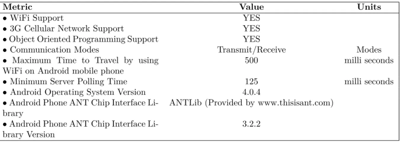
According to requirements of android mobile application, metrics are stated as below.
Metric Value Units
• WiFi Support YES
• 3G Cellular Network Support YES
•Object Oriented Programming Support YES
• Communication Modes Transmit/Receive Modes
• Maximum Time to Travel by using
WiFi on Android mobile phone 500 milli seconds
• Minimum Server Polling Time 125 milli seconds
• Android Operating System Version 4.0.4
•Android Phone ANT Chip Interface
Li-brary ANTLib (Provided by www.thisisant.com)
•Android Phone ANT Chip Interface
Li-brary Version 3.2.2
Table 3.6: Mobile Platform Metrics
3.3.3
Web Service Requirements
In this thesis, web server is a tool of Earl that enables technology designers to control actuators and monitor sensor data. These two fundamental functionalities help technology developer to create systems. By using web services, application designers can merge their applications with other web services. By this way, designers can facilitate early design processes by having help from other web services.
In this section, I listed requirements of web services. These requirements are connected to design objectives as previous requirements.
Requirements Design Objectives
• Earl is a toolkit that connects small systems to web services with wireless
technology. DO7
• Technology developers can do complicated process on the Earl web server
instead of Earl hardware toolkit. DO4
Table 3.7: Earl Web Platform Requirements Metrics of web services are listed below in Table 3.8.