Design Automation Systems – Supporting
Documentation and Knowledge
Manage-ment
Jie Nan
Qian Li
This exam work has been carried out at the School of Engineering in Jönkö-ping in the subject area Product Development and Materials Engineering. The work is a part of the Master of Science programme.
The authors take full responsibility for opinions, conclusions and findings pre-sented.
Examiner: Joel Johansson Supervisor: Fredrik Elgh Scope: 30 credits Date: 2012-09-21
Abstract
1
Abstract
During the practical use of Design Automation (DA) System in a company, the lack of assistance from either documentation work about the whole system or management of knowledge could bring out some obstacles when engineers reuse existing knowledge and information. The purpose of this project is to explore an approach of documentation and knowledge management in DA System. The study is mainly based on the actual case of seat heater DA system developed by JTH.
Based on preset functional requirement for the potential solution, several princi-ples and methods of documentation and knowledge management are introduced such as MOKA, CommonKADS, SysML and PVM. A number of useful applica-tions such as DRed (Design Rationale Editor), PC PACK, Sementic MediaWiki and Product Model Manager became candidates solutions for this project. The selection of final approach was Sementic MediaWiki, and this is based on the comparison of the result from evaluation of functionality of each application. Due to specificity of documentation on the DA system, the “process based” ap-proach had been used for structuring system included knowledge instead of using a systematical method like either MOKA or CommonKADS completely. Setting up interconnection between different knowledge objects was one of the most im-portant tasks in this project because it enables capturing and retrieving of knowledge.
Sementic MediaWiki, a powerful text representative and web-based tool has been used as a platform of representing the whole knowledge and information. With its implementation, the performance of Sementic MediaWiki had been tested accor-ding to the preset functional requirement. After a slight refine process to the solu-tion, the satisfactory result had been achieved, and also proved the applicability of Sementic Wiki in such kind of project.
Keywords
Documentation, Knowledge Management, Semantic MediaWiki, Design Automa-tion system.
Contents
2
Contents
1 Introduction ... 4
1.1 BACKGROUND ... 4
1.1.1 Back ground of R&D ... 4
1.1.2 Theoretical principles ... 4
1.1.3 Introduction of ProcedoStudio ... 6
1.2 PROBLEM DEFINITION ... 9
1.2.1 Problems, need and company’s perspective ... 9
1.2.2 Academic perspective ... 10
1.3 PURPOSE AND RESEARCH QUESTIONS ... 12
1.4 DELIMITATIONS ... 12 1.5 OUTLINE ... 13 2 Frame of Reference ... 14 2.1 PRODUCT DEVELOPMENT ... 14 2.2 ENGINEERING DESIGN ... 14 2.3 DESIGN AUTOMATION ... 16
2.4 KNOWLEDGE-BASED ENGINEERING (KBE) ... 17
2.5 DESIGN RATIONAL AND DOCUMENTATION ... 18
2.6 SUMMERY ... 19
3 Functional Requirement ... 20
3.1 DEFINITION OF REQUIREMENT ... 20
3.2 DEFINITION OF FUNCTIONS ... 20
4 General Principles and Applications ... 24
4.1 INTRODUCTION OF PRINCIPLES ... 24 4.1.1 SysML ... 24 4.1.2 MOKA ... 27 4.1.3 CommonKADS ... 29 4.1.4 PVM ... 30 4.2 INTRODUCTION OF APPLICATIONS ... 32
4.2.1 Design rational editor ... 33
4.2.2 PC Pack ... 34
4.2.3 Semantic MediaWiki ... 35
4.2.4 Product model manager ... 36
4.3 SUMMARY ... 38
4.4 IDEAS OF ALTERNATIVE APPROACH ... 38
4.5 EVALUATION AND SELECTION OF APPROACH ... 38
5 Development and Implementation ... 39
5.1 COLLECTING KNOWLEDGE AND INFORMATION ... 39
5.2 STRUCTURING KNOWLEDGE ... 40
5.2.1 Design sequence electric ... 42
5.2.2 Design sequence geometry ... 46
5.3 IMPLEMENTATION ... 56
5.4 TEST AND EVALUATION ... 62
5.5 APPLICABILITY AND GENERALIZATION ... 66
6 Discussion and Conclusions ... 67
6.1 DISCUSSION OF SOLUTION ... 67
6.2 DISCUSSION OF METHOD ... 67
Contents
3
Introduction
4
1 Introduction
The objective with this project is to explore approaches for documentation and knowledge management of design automation systems. A solution is to be deve-loped for industrial case with required functionality for capturing, structuring, searching, retrieving, viewing, and editing the system embedded information and knowledge. Based on the evaluation of various approaches, an appropriate appli-cation will be selected as a solution and implemented according to the relative method. The final solution will be tested based on the preset functional require-ments and refined for elimination of problems occurred during the tests. The final solution will enable and facilitate system maintenance, updating and support the reuse of functions and system encapsulated generic product family descriptions.
1.1 Background
As design automation system increasingly applied on customized product, there is massive information and knowledge included in DA system. It is difficult to un-derstand for new users how the system works and how the knowledge is related to each other. This kind of documentation system will help users to understand de-sign automation system that includes the specifications, parameters and rules, also the relationships among them. This will enable the company’s data systematiza-tion, classification and integration.
1.1.1 Back ground of R&D
For many products, the adaptation to customer specifications is essential and re-quires flexible product design and manufacturing while maintaining competitive pricing by ensuring enhanced producibility (Elgh and Cederfeldt, 2005)[1]. Since customized product strategy is adopted by many companies and in order to en-hance competitiveness of such strategy companies themselves, the vision and methodology of automation design system was introduced in, and successfully implemented as well. This technology is not only a means of improved efficiency but also a method for reduced lead times, improved offer precision, quality assur-ance, performassur-ance, and enables a higher degree of customer adaptation.
1.1.2 Theoretical principles
The basic tasks of DA system development are to retrace all variables defining the product and the formalization of the corporate knowledge during design process. The system should be able to adapt with the data increase, diversification and changes of product design over time in the area of product technology, product knowledge, production practice, customer requirements and legalizations and so forth. Hence, for DA system, adaptation of the improved knowledge which gov-erns design is critical and essential. Furthermore, extensiveness and feasibility for different product systems are also the important facts in developing DA system. The main architecture is depicted in Figure 1-1. Knowledgebase consist several series of files which are executed by different applications while an inference
en-Introduction
5
gine is used to solve the execution sequence of files. A simple and clear interface achieves user interaction, while the Database is used for connecting enormous knowledge data.
Figure1-1 Principle system architecture [2]
At those point, DSM (Dependency Structure Matrix) is used to present the de-pendencies between items, and cluster the statements into several different blocks and show the identification of structural levels (Figure 1-2).
Figure 1-2 Part of the DSM of ProcedoStudio(By Elgh, F.)
DA system realization:
Theoretically, in the system development process Retrace the required knowledge
Close gaps between process and knowledge definitions From the system functional perspective
Easy to reuse the existing knowledge and information
Integrate and automate both design process and quotation activities Speed up the total engineering process with high accuracy result
Introduction
6
1.1.3 Introduction of ProcedoStudio
ProcedoStudio is an automatically design software which was developed for KA company, mainly used for automatic design of wiring patterns for car seat heaters. It is used in quotation process to rapid assessment for bids with high accuracy. As further improving, this application will be use in other customized products. ProcedoStudio is used in Windows system. User interface is programmed by Vi-sual Basic. Application programs which are invoked by ProcedoStudio during the auto-design process include MS Access 2007, MS Excel 2007, MathCAD 13 and CATIA V5R18. Inference engine combines these programs with knowledge ob-jects in Knowledge base to achieve design automatically according to customer specified input parameters and variables. The main structure of ProcedoStudio is shown in Figure 1-3. The knowledgebase comprises rules in CATIA VBA, Excel and MathCAD.
Figure 1-3 ProcedoStudio System architecture[3]
Introduction
7
Presently, there are 20 KnowledgeObjects constituting the domain knowledge of designing heating elements. It includes:
Input 4 pcs. Electrical calculations 11 pcs. Geometry 2 pcs. Wire layout Amplitude factor Manufacturing pcs. Cost 1 pcs. File handling 2 pcs.
The number of Variables manage by database is 66, although the total number of Variables residing in all of the KnowledgeObjects is of much larger. [4]
In the beginning of user interface, the “Available knowledge databases” and “Pro-ject” need to be defined (Figure 1-5). When click “new” button, the program will show the customer specified dialog (Figure 1-6). In the user interface, users can click relevant button and add input parameters by selecting needed files in the popup windows. The whole process is visible. Also, user could select different check box to present the order, popup invoking programs and files. After running program, the prototype will be showed in CATIA with 2D draft (Figure 1-7), and all the calculations results will be shown in the window (Figure 1-8).
Introduction
8
Figure 1-6 customer specified process
Figure 1-5 2D sketch layout
Introduction
9
1.2 Problem definition
In this section, since this project is based on actual case, problems and need of this project will be indicated from both company’s perspective and academic per-spective. It will help to define the purpose and research question of the project.
1.2.1 Problems, need and company’s perspective
In the previous project, the design automation system of seat heater has been de-veloped by School of engineering, Jönköping. It provides a significant reduction on lead-time and brought efficiency in doing design work and quotation process to the company (KA). From the company’s perspective, the fact that the system is running with good condition for a long period can be expected. During the practi-cal use of the system in the company, the lack of assistance from either documen-tation work about the whole system or management of knowledge could bring out some obstacles when the engineers from the company reuse existing knowledge and information without some helps from original developers. As a result, it will significantly delay company’s developing activities, and engineers would be faced great challenges to finish with design tasks and quotation process. Hence, be able to bring full comprehension of both overview of entire system and detailed rela-tionships between different knowledge and information to the users from the company, it is an essential task that explore how to deal with the mapping be-tween scattered knowledge and information which are presented in Figure 1-9.
Figure 1-9 Knowledge representation of entire system (by Elgh, F.)
From a long-term point of view, reuse of the existing knowledge is a critical issue, since there will be introduction of new product, new variant of existing product, new manufacturing process and additional or modified design rules due to new insights or changes in standards or legislation. In order to deal with these “New” factors, the adaptability of entire system need to be considered, and some
support-Introduction
10
ive documentation work and management of knowledge need to be accomplished for achieving the goal of maintenance of the system, updating and reuse of system embedded information and knowledge.
1.2.2 Academic perspective
Nowadays, despite many studies of knowledge acquisition and storage for setting up design automation systems, [5, 6] the aspect of maintaining and updating such systems has received rather little attention in the academic world, while companies have faced the practical problem for a long time.
A principle development process is illustrated in Figure 1-10.
Figure 1-10 Company Development process, information and repositories[4]
There will be many documents, files and items created and stored in different re-positories during the development process at the company. It is vital that make connections between these existing knowledge and information with a good man-ner which are located in different repositories in order to get the traceability of objective knowledge.
In the product development process knowledge are processed in different steps and appears in different states. Six knowledge states can be identified and these are: unprocessed, selected, structured, adapted, utilized and documented (Figure 1-11). [4] To support reuse, expansion and maintenance of different Knowledge Objects (building blocks) it is required that the focus in the product development process is not limited to the definition of Knowledge Objects exclusively, but also include the definition and collection of associated Meta-Knowledge[4]. Fredrik Elgh pointed out that “Meta-knowledge” can be regard as knowledge that is ap-plied to determine how to execute other knowledge. [4] Comparing with a design automation system, human designers have a higher degree of flexibility on deci-sion making based on e.g. experience, rules of thumb or numerical calculations,
Introduction
11
and also on selecting appropriate method or solution based on comparison be-tween different solutions. This kind of ability is expected to be introduced in de-sign automation system for achieving a better ideal solution. Although, the con-cept of meta-knowledge is well established in the AI world, but its application in practical engineering design problems needs to be adapted and further developed.
Figure 1-11 Knowledge States [4]
Since the design automation system is developed based on KBE (Knowledge Based Engineering) applications to some extent, there are some issues need to be notified.
Transparency of KBE applications:
In order to make more user-friendly, flexible and adaptable knowledge bases, the black-box applications should be moved away. The approach to this purpose is by using sustainable knowledge in KBE, which means the underlying knowledge and supporting documentation for the KBE application should be directly accessible. Another important aspect to level up the transparency of KBE application is use management of the evolution of application. This might be achieved by using more advanced knowledge management techniques and features such as knowl-edge life-cycle management. [7]
Enriching the semantics of knowledge models and their traceability in KBE implementation:
Achieving interoperability enables “data connection” between heterogeneous sys-tems to be used into KBE tools and vice versa. Further exploitation of data enti-ties in KBE automation tools requires a “knowledge connection” where not only the syntactic content of the data but its common meaning is exchanged, an essen-tial principle of the so-called “Semantic Web”. [7]
Documentation is mainly focused on describing the final results of different activi-ties answering “What?” questions. For example, to reuse a rule in a new context (another product family) requires more information, such as scope, range, simpli-fications and underlying assumptions. Such information might be enough if the rule is to be used as it is, but if the rule has to be modified and adapted to specific circumstances even more information is required to support the adaptation while ensuring the validity of the rule [4].
Introduction
12
This thesis project will be undergoing with more detailed questions (pointed out by Elgh, F.) concerning the knowledge management which are listed below:
How can the executable design rules be documented, structured, validated and made traceable to their associated design knowledge?
What “meta knowledge” strategies are relevant for applications in engineering design?
How can the scattered knowledge be connected with reasonable manner that make them traceable from both backward and forward directions?
Some common facts need to be considered, they are:
The current case is not the only target of the potential solution that will be developed in the future.
The coming solution should be established on both industrial and academic base, which means the solution will be tested and evaluated for the practical applicability at the company. Whilst from an academic point of view, the solu-tion should be supported by correct and rigorous theories.
1.3 Purpose and research questions
It is essential that for both system longevity and carry-over when developing new product families and the documentation of the system embedded information and knowledge for maintenance, updating and reuse. The objective with this project is to explore approaches for documentation and knowledge management of design automation systems. A solution is to be developed for the industrial case with re-quired functionality for capturing, structuring, searching, retrieving, viewing, and editing the system embedded information and knowledge.
The solution will enable and facilitate system maintenance, updating and support the reuse of functions and system encapsulated generic product family descrip-tions.
1.4 Delimitations
The main task of this thesis is about documentation management. It will focus on working with managing with support document of DA system to show how it works or relate to each other. Supporting documents here include CATIA, EX-CEL, and MathCAD files which will be used during the automation design pro-cess, and also instruction file for showing the relationship clearly. This thesis does not include developing the problem itself and the huge date base behind the pro-gram (ACCESS). Further, the document used during the auto-design process will also not be revised.
Introduction
13
1.5 Outline
Problem definition is set after a general introduction and analysis of Procedo-Studio and seat heater. The related theoretical background detailed in the chapter of “frame of reference”. General Principles and Applications have been compared with the preset functional requirements to select a best option. Structuring Knowledge and implementation of MediaWiki are explained in the chapter of “Development and implementation” as well as test and refine process. The discus-sion, conclusion and future works have been indicated in the last chapter briefly.
Frame of Reference
14
2 Frame of Reference
The purpose of this project is to explore a reasonable approach to represent the knowledge and information underlying DA system. A brief overview and intro-duction of related supporting theoretical domains need to be reviewed. They are: product development, engineering design, design automation, knowledge-based engineering, design rational and documentation.
2.1 Product development
Product development includes all the activities when companies developing a new product with good performance, low product cost, less development time and minimum development cost. Ulrich and Eppinger defined product development as “the sequence of steps or activities that an enterprise employs to conceive, de-sign and commercialize a product” [8]. Kotler al. (1999) pointed out the new product developing process can be divided into nine steps, as indicated in Figure 2-1. [9]
Figure 2-1 Nine steps of developing process [9]
Recently, due to dramatic increasing globalization and customer’s extensive de-mands on product value, effective product development process is becoming more and more vital issue from the company business strategy. According to Smith and Reinertsen (1998), the four key product development objectives are: the right performance for the right product cost within the right development time at minimum development cost. [10] Product development process comprise highly creative and knowledge-intensive tasks that involve extensive information ex-change and communication among geographically distributed teams. [11] During the product development process, large amount of, variety of information and knowledge are generated by the engineers and designers. It is essential challenge that ideally deal with these product related knowledge in order to improve the ef-ficiency of the development process.
2.2 Engineering Design
Design is development and realization of something new in systematic way. The result may be a product, a physical object manufactured to satisfy a need while fulfilling all the initial requirements set by different groups of interested par-ties.[10] In the context of product development, the core of engineering design is the activities within the product design that are accomplished through systematic
Frame of Reference
15
application of engineering principles and physical and mathematical concepts to solve problems.[10]
The main four phases in engineering design outlined by Pahl and Beitz (1996) are [10, 12]:
Planning and clarification of the task:
Starts with an analysis of the market and the company’s situation Result in a product idea and a requirement list.
Conceptual design:
Identification of essential problems
Establishment of functions structures and solutions that are combined into solutions
Evaluation and selection of concept
Embodiment design:
Creation of preliminary layout designs including materials and calculations Refining, improving and evaluating
Results in a preliminary layout that is processed into a definitive layout
Detail design:
The arrangement, form, dimensions and surface properties of individual parts are set
The output from this phase is the specification of production
Engineering design is can be considered as a problem-solving process, it compris-es a lot of succcompris-essive decisions in many possible solutions. The systematic ap-proach that making right decision from the initial problem definition to the final solution need to be applied during the whole development process. Meanwhile, it is important that evaluating the feasibility of the possible solutions according to right information, in order to make a correct direction on reaching final goal of development.
Frame of Reference
16
2.3 Design automation
Nowadays, company expense a lot of effort, resources and time on dealing with product designing tasks and quotation process. Design automation system com-bines computer technology with engineering design for enabling efficient design process. There are many redesign activities of an existing product in the company, and according to Encanacao et al. (1990) perhaps more than 90% of industrial design activity is based on variant design. [10] “Engineering IT-support by imple-mentation of information and knowledge in solutions, tools or systems, that are pre-planned for reuse and support the progress of the design process. The scope of the definition encompasses computerized automation of tasks that directly or indirectly are related to the design process in the range of individual components to complete products”. [1]
Elgh, F. pointed out design automation can be divided into two types: information handling and knowledge processing. [10] For instance, an archiving system for the reuse of CAD-files and spread sheet of calculation of a prismatic object and so forth. There also have large amount of knowledge such as rules and algorithms for variant design which are incorporated with a PDM system.
According to Elgh, F., the aim of design automation is to support one or more of the following areas: [10]
Design synthesis: includes computerized templates for calculation/optimization
of design parameters, applications for calculation/optimization and generation of product geometry, applications that ensure producibility, database systems sup-porting the reuse of previous solutions, information systems for requirements or manufacturing constraints, configuration systems, etc.
Design analysis: by, for example, automated: finite element analysis, geometry
preparation for finite element analysis, evaluation of producibility, cost estimation, etc. based on a geometry description and/or design characteristics.
Plan for manufacture: comprise computer-aided process planning for the
gener-ation of, for example: opergener-ation sequences, production parameters, machine con-trol commands, fixture and jig designs, etc. based on a geometry description and/or design characteristics.
The main objective of design automation is achieve the effective and efficient product development process by reducing costs, cutting lead-time, improving product performance and adapting product to different customer specifications.
Frame of Reference
17
2.4 Knowledge-based engineering (KBE)
Knowledge-Based Engineering is a research field that studies methodologies and technologies for capture and reuse of product, process and engineering knowl-edge. The objective of KBE is to reduce time and cost of product development, which is primarily achieve through automation of repetitive design tasks wile cap-turing, retaining and reusing design knowledge.[13] Many company nowadays, increasingly moving towards mass customization and this requires relatively rapid and collaborative design process and producing process. KBE has its roots in the 1980s, when the application of Artificial Intelligence (AI) and Knowledge Engi-neering techniques in Computer Aided Design (CAD) became known as Knowledge-Based Engineering.[14, 15] KBE is mainly applied for automating repetitive design process and this is dramatically cutting the lead-time which ena-bling designers devote more effort on the creative and various design tasks. A ma-jor advantage in adopting KBE is presented in Figure 2-2 below.
Figure 2-2 Achievable design time allocation by KBE adoption [16]
There are several KBE methodologies available to support the development of KBE applications and systems, such as methodology and software oriented to KBE applications, MOKA methodology and KOMPRESSA methodology. [13] A number of research challenges in knowledge-based engineering have been ad-dressed in the conference paper [13], they are:
Improve methodological support for KBE.
Moving beyond black-box KBE applications: Transparency of KBE applica-tions; enriching the semantics of knowledge models and their traceability in KBE implementation.
Effectively sourcing and re-using knowledge. KBE success metrics.
Frame of Reference
18
2.5 Design rational and documentation
Design rationale is an explanation of why an artifact or some part of an artifact, is design the way it is [17]. The processes of maintain and redesign require much effort to understand previous work in the whole product life cycle. Design ra-tionale does a crucial assistance of structuring design problems, presenting related principles to explore more design options. Design rationale system be used as a basis to discuss and reason among collaborating designers which including all back ground knowledge, such as deliberating, reasoning, trade-off and decision making in the design process of an artifact-information that can be valuable, even critical, to various people who deal with the artifact[18].
A design rationale system which is constructed by domain-specific knowledge is used as a representation framework for designers discussing and reasoning. The first approach to design rationale was proposed in 1970 [19], after that, various methods have been proposed and developed, and the exploration never ends. There are two main approaches to developing design rationale systems: process-oriented and feature-process-oriented. Feature-process-oriented approach focus on the representa-tion of artifacts and established rules governing the design process, while process-oriented approach is often used to create a historical representation of the design process. [18, 20, 21]
Capture of design rationale is critical process. In design rationale system, the in-formation captured is used to answer or will answer or infer the questions raised by designers. In design process design rationale is captured by recording rea-soning, decisions, options, trade-off, dependency relations between data and in-formation, etc., and constructing a formal [22] or semi-formal structure[20] so that the design rationale can be used in the decision-making process during design. The design rationale capture process divide into knowledge recording which refer to capturing raw information and design rationale construction focus on organize and store knowledge. Both of these two processes can be implemented by auto-matic capture and user-intervention.
Generally, design rationale system is supported by knowledge-based systems and CAD/CAM system [18]. It contributes to design progress by provide designers with a knowledge representation framework, as well as tools to capture design rationale, design reasoning and communication during the design process.
The purpose of documentation is to describe software system, and record the rel-evant process steps of creation, updating, modification and deletion. Consistent, correct and complete documentation of software system is an important vehicle for the maintainer to gain its understanding, to ease its learning and /or relearning processes, and to make the system more maintainable [17]. It is integrated to pre-sent and show the architecture of the software system and the process steps which are visible and visualized to people who need to entirely acquaint. Furthermore, the reasons of some software systems outdated are degradation of the documenta-tion system, which made the problems become more complicate and confusion. Consequently, a correct, complete and consistent documentation is a powerful tool for improving users’ efficiency and work quality, and gain success.
Frame of Reference
19
2.6 Summery
Several knowledge domains had been briefly introduced for a better understand-ing of theories concerned with this project. For instance, the theories regardunderstand-ing to product development and engineering design can be the basic theories that need to be reviewed, and the part of knowledge based engineering and design automa-tion brings a short comprehension to the DA system. Since the part of design ra-tionale and documentation can be our implication of potential solution, there could be more exploration needed regarding to this knowledge domains. To con-clude, for both better comprehension to this project and exploration of solution, the theories introduced in previous sections in this chapter will be useful.
Functional Requirement
20
3 Functional Requirement
Based on the study and realizability of DA system, a series of requirements of the knowledge representing system will be discussed. Accordingly, the specific func-tions which could realize the requirements will be explored and expounded.
3.1 Definition of requirement
First of all, because of this project is mainly based on the actual case (Design au-tomation system of seat heater from KA), there are a lot of existing knowledge and information such as specifications, CAD model templates, CAD-macros, de-sign rules and regulations, cost estimations and calculations etc. are generated by the designers and engineers during the developing and design process of the de-sign automation system. These knowledge and information are scattered over and stored at different repositories, or might be saved by a specific individual who is responsible for managing the project.
In order to deal with documentation and knowledge management tasks, we should answer the question “What do we totally have in this DA system?” There are four main different sorts of knowledge that are consisted in design automation system. They are the knowledge that generated in product development process, in engi-neering design process, in data processing and about application system respec-tively. It is very important task that collecting these knowledge which will be doc-umented and managed.
Another common question is “How are the information and knowledge distri-buted, related or connected?” For a better understanding and utilization of design automation system, there is significant need to make clear view on principle of design automation system, and also explore and present the interconnections be-tween these information and knowledge to the possible system users. Design ra-tionale is an effective way of capturing this missing part of an integrated represen-tation of design knowledge, and can be defined from a variety of viewpoints.[23] The possible functions of our potential solution will be followed by the question “What knowledge and information should we concern, and how should we ma-nage with that if we want to reuse (system embedded knowledge), maintain and update”.
3.2 Definition of functions
In this section we will explore and define what functions of our potential solution are, and why we need these functions. The main function of our objective solution is enable documentation task and knowledge management task for the design au-tomation system. From a product development perspective, by using our possible solution engineers could indicate their ideas or thinking which are occurred during the product development process, such as planning the development process, manufacturing process and quotation process. From an engineering design per-spective, designers also could represent how the optimal designs came out which will allow the designers can easily make changes in future design work. Some ex-tent of representative design rationale on IT area is also helps system maintenance, and knowledge management skills will be needed for a better systematically
man-Functional Requirement
21
aging the existing knowledge which will provide convenience on traceability and system updating activities. The possible function of our potential solution will be indicated by following sections, they are:
Creating: Create new project or product family. Adding design rationale
Creating function is the most common function that exists in almost all the com-puter system that creating new files, new tasks and new specifications and so forth. In our case, it will be the function that creating a new project, for instance, the documentation system is not only working for seat heater design automation system, it also could create another jobs or project for other specific product. The creating function is also responsible for create new product family, and add design rationales for specific design task and so on.
Locating: Locate/Collect underlying or supportive files and documents.
Since there are several different software used and served for design automation system, there exist different supportive files that had been generated by designers and engineers such as Microsoft Word files, Excel files, Catia model files, Catia VBA macro files, Visual Basic GUI and Database Access files and so forth. The locating function is to gather these relative files that are stored in different reposi-tories, and make a connection to our objective system, for enabling accessibility to these files. It is an introducing processes that gathering and localizing supportive files to our documentation system.
Managing: Document Management and Knowledge Management/Information
Management
Managing function could be the most vital function of our documentation system. There might be necessary to divide this task to some extent, because knowledge management is a big and wide area and it always hard to find an appropriate ap-proach to a specific management task. In this section, we intend to classify the management function as two different approaches.
The first function would be aiming to the document management activities. Sys-tem underlying document management, such as supportive documents, and design rationale documents, recorded documents which is mainly recording the modifica-tions and output variables and historical generated computational files, all of the documents need to be managed, classified with an appropriate way.
The other function is to manage the knowledge and information that are consisted in the product, development process and application process. These knowledge and information will represented by several approaches. For example, design ra-tionale approach, graphical representation, text transformation of computer code, setting up interconnection between different variables and so on. The key point of this function is to capturing the objective information or knowledge correctly and efficiently for reusing, system maintenance and updating activities. The possible approach will be explored and evaluated in the next phase of this project.
Structuring: Product structuring (Part, assembly, material etc.); Process
struc-turing: Design process, Quotation process, computational running process; Prod-uct family strProd-ucturing: Input specification, associated variable specification etc.
Functional Requirement
22
Structuring, to some extent, its functional meaning is related to the management function. It aims to ideally organize existing knowledge or information, and pre-sent a clear and vivid view of knowledge structure and process structure to the users. Based on seat heater design automation system, there would have a signifi-cant need for representing product structure (such as part, assembly, material etc.). In the seat heater design automation system, it contains nicely structured product family. For example, input variables, customer specifications, associated design variables, output variables and so on. In our documentation system, if we can also present this sort of structures to bring a better understanding of information to the users and easier the accessibility to objective knowledge.
Process documentation should be pervasive in and through all of the types of de-velopment and maintenance chores. Proper control and management of develop-ment and maintenance can only be achieved if we have obtained sufficient visibil-ity into the process, its stages and tasks, executing roles, their decisions and moti-vations, and the results of each individual process task.[24] Design process as KM (Knowledge Management) core: the design process forms a central element of the knowledge management method, either though process templates, product model integration or knowledge-based process support.[25]
In our case, we intend to make a clear view of the design process of seat heater wire, quotation process and computational running process by mapping and struc-turing different processes. In order to deal with such tasks, the strucstruc-turing func-tion is vitally needed.
Access: Open/Read/Modify/ (Authorization)
There is no doubt that the function of accessibility is the most basic function in such documentation and management system. Opening the files, read the infor-mation that contained in the files, and enables modification of some relative vari-ables depends on different circumstances. The issue of setting up some extent of authorization is desired for the company to insurance information security. The individual who is going to make some modifications on the design variables and rules must take full responsibility for such changes.
Edit: Text, Graphical Approach, Figure
Editing function is on purpose of representing better descriptions on the product, process and application system. Editing function will include both text format approach and graphical approach which would provide higher visualized, trans-parent reflection to the possible users. It is the essential function on dealing with design rationale tasks such as either issue based design rationale or process based design rationale.
Link: Issues, variables, rules, process, constraints, code-Links to the design
Functional Requirement
23
Link function can be considered as the most fundamental function that achieving knowledge traceability. Such as the issues, variables, rules, process, constrains and computer code will be documented and descripted specifically (consist description of relative issues, variables, constraints and rules etc.) to some extent by the de-signers in the late of design stages. Building up the links between the sensitive is-sues, variables and rules to the respect design rationale is to help the users to find the relative knowledge in an efficient way. Another possible, desired function is that construct the links in an advanced, multi-connected level. For instance, links between variable and variables, variable and rules, variable and constraints and so forth.
Search: History Design/Project (store, open, view)
As constantly using design automation systems, there would be enormous gene-rated information because of over and over execution. In order to manage this large amount of information, and retrieve the objective information, reuse existing knowledge, historical searching function is becoming a necessity.
Recording: Modified Input variable, output, rules, regulations and calculations.
The purpose of documentation however, is not only to describe a software system but also to record all the relevant process steps leading to its creation, update, modification, and deletion.[24]
The recording function is mainly targeting to enables traceability of sensitive mod-ification activities such as input variables, design parameters, rules and design put. Recording would be done by documenting the modifications and system out-put for each project. It will provide not only some extent of traceability, but also comparability between different test. And some comment from the users or de-signers that concerning the design knowledge would also be recorded as experi-ence for future design tasks or test activities.
General Principles and Appications
24
4 General Principles and Applications
According to the requirements and functions identify in Chapter 3, several differ-ent suitable principles and applications supporting the solutions have been sur-veyed in the related field. In this chapter, principles and applications will be intro-duced briefly and generally. After comprehensively comparing with the alternative solutions, the final approach will be determined.
4.1 Introduction of principles
The principles are the theoretical methods to solve the analogous problem such as knowledge structure, documentation, design rational capturing and so forth. SysML, MOKA, CommonKADS and PVM are the four selected principles intro-duced as follow:
4.1.1 SysML
SysML is a general-purpose graphical modelling language that supports the analy-sis, specification, design, verification, and validation of complex systems. These systems may include hardware, software, data, personnel, procedures, facilities, and other elements of man-made and natural systems.[26] The language is intend-ed to help specify and architect systems and specify their components that can then be designed using other domain-specific languages such as UML for software design and VHDL and three-dimensional geometric modelling for hardware de-sign[26].
SysML can represent the following aspects of systems, components, and other entities:[26]
Structural composition, interconnection, and classification Function-based, message-based, and state-based behaviour Constraints on the physical and performance properties Allocations between behaviour, structure, and constraints
Requirements and their relationship to other requirements, design elements, and test cases
There are nine different sorts of diagrams in SysML, they are package diagram, requirement diagram, activity diagram, sequence diagram, state machine diagram, use case diagram, block definition diagram, internal block diagram and parametric diagram respectively.
Considering the potential use in our project, some of specific parts will be dis-cussed in this section. In SysML, constraint blocks are to support the construction of parametric models. A constraint block is a special kind of block used to define equations so that they can be reused and interconnected.[26] In constraint blocks a set of parameters are constrained by an expression. A constraint block can be presented on both a block definition diagram and parametric diagram.
General Principles and Appications
25
SysML includes a generic mechanism for expressing constraints on a system as text expressions that can be applied to any model element.[26] SysML does not provide a built-in constraint language because it was expected that different con-straint languages, such as the Object Concon-straint Language (OCL), Java, or MathML, would be used as appropriate to the domain.[26]
The element that owns the constraint is shown as a symbol with compartments, such as a block, the constraint can be shown in a special compartment labeled constraints. A constraint can also be shown as a note symbol attached to the model element(s) it constrains, with the text of the constraint shown in the body of the note. [26] Figure 4-1 shows examples of the different constraint notations used in SysML.
Figure 4-1 Example of two notations for showing constraints [26]
The complex constraint blocks on a block definition diagram can be placed hier-archically in order to present the relations, see Figure 4-2.
Figure 4-2 A hierarchy of constraints on a block definition diagram [26]
A rationale is a SysML model element that can be associated with either a re-quirement or a relationship between rere-quirements, or any other model element. As the name implies, the rationale is intended to capture the reason for a particu-lar decision. Although rationale is described here for requirements, it can be ap-plied throughout the model to capture the basis for any type of decision. A
prob-General Principles and Appications
26
lem is depicted like a rationale, but is used to identify a particular problem or issue that needs.
In Figure 4-3, the rationale is presented as text symbol with the keyword «ra-tionale». The specific expression of the rationale is presented under the key word, and also the relative reference could be connected with by a hyperlink. In this par-ticular example, there is a reference to a trade study, T.1.[26] The context for this particular rationale is shown in Figure 4-4.
Figure 4-3 Example of rationale as depicted on any SysML diagram [26]
Figure 4-4 Example of the rationale attached [26]
A rationale or problem can be attached to any requirements relationship or to the requirement. For example, a rationale or problem can be attached to a satisfy rela-tionship, and refer to an analysis report or trade study that justifies the assertion that a particular design satisfies the requirement. Similarly, the rationale can be used with other relationships such as the derive relationship. A rationale can also be attached to a satisfy relationship that references a test case which verifies the requirement is satisfied.
General Principles and Appications
27
4.1.2 MOKA
MOKA stands for:
“Methodology and software tools Oriented to Knowledge based engineering Ap-plication”. [5]
The MOKA project was aimed at reducing the amount of up-front investment and risk associated with the development of KBE applications.[5] MOKA is the methodology which is mainly developed to support KBE, the tasks includes: [5] Describing a lifecycle process to guide the user in applying the concepts; Finding appropriate ways to represent both the product and process
knowl-edge of the application;
Building a software tool to enable users to implement the methodology.
The lifecycle of a KBE system adopted for use within the MOKA project is shown in Figure 4-5.
Figure 4-5 KBE lifecycle identified in MOKA [5]
Consequently, support of the KBE life cycle is a useful function of the KBE methodology. This resulted in the introduction of the MOKA life cycle.
Two different sorts of knowledge representation layers are used in MOKA. The first is designed to be very user-friendly and to represent the thinking of the engi-neers in many different ways. It is called the Informal Model, and the knowledge is classified into five types in this model, they are: [5]
Illustrations-for recording past experience, case histories, anecdotal knowledge;
Constraints-restrictions on the objects or the attributes of an object; Activities-the elements of the design process
Rules-knowledge that directs choices in the activities; Entities-the objects that describe the product
General Principles and Appications
28
Each knowledge type has a specific template or form. The set of completed forms, called ICARE forms, holds the knowledge description for the KBE appli-cation. 5] The set of linked ICARE forms is the minimum for describing a MOKA Informal model. To make visualization of the links easier, MOKA allows for charts to show the way the product is made up in terms of structure and func-tion as well as to illustrate the sequences in the design process (see Figure 4-7). The ICARE forms can provide a useful reference and training guide for product and design process. The example of Informal model shows in Figure 4-6 below.
Figure 4-6 The ICARE forms used in MOKA Informal Model [5]
Figure 4-7 Charts help to visualize the links between the ICARE forms [5]
The second layer of representation is the Formal Model. The knowledge engineer takes the knowledge from the linked ICARE forms and converts it into a UML-style of representation.[5] This second level is not intended specifically to be read-able by Experts. Its purpose is to prepare the knowledge in a form that is more checkable by a computer and begins to resemble the representation of the knowledge in coded form that might be used on the KBE platforms.[5]
The Formal Model has two key elements: the Product Model and the Design Pro-cess Model. The product model is divided into five views that allow the represen-tation to be constructed in a modular fashion. [5] They are: Structure; Function; Behaviour; Representation; Technology. These views are constructed as UML Class Diagrams. MOKA provides meta-models as a container framework for the knowledge that is held in the Informal Model. [5] The meta-models are used as a guide to build knowledge models that fit the particular application.
The Design Process Model is based mainly on Activity Diagrams to show the se-quence of the process and the relation of the elements in the product model to the process. The diagram is showed below in Figure 4-8.
General Principles and Appications
29
Figure 4-8 The default meta-classes for the MML view structure [31]
4.1.3 CommonKADS
CommonKADS is short for Common Knowledge Acquisition and Documen-tations Structuring and was developed as a respond to the need for a standard for knowledge-based system. [27] It is a set of comprehensive methodology used for structuring and managing knowledge as well as developing the knowledge-intensive system and so forth. The structured approach is based on following principle of knowledge engineering:
Knowledge engineering is not some kind of “mining from the expert’s head”, but consists of constructing different aspect models of human knowledge. The CommonKADS model suite is a convenient instrument to break down and structure the knowledge-engineering process. [27]
The knowledge-level principle: in knowledge modelling, first concentrate on the conceptual structure of knowledge, and leave the programming details for later. In CommonKADS approach, the later is the foremost viewpoint. [27] Knowledge has a stable internal structure that is analyzable by distinguishing
specific knowledge types and roles. [27]
A knowledge project must be managed by learning from your experiences in a controlled “spiral” way. [27]
CommonKADS shows the approach of the problem face by Knowledge En-gineers by represent the expert knowledge and design specification in form of text or diagrams. [27]
CommonKADS mainly defined six kinds of modules: Organization model, Task model, Agent module, Knowledge model, Communication model and design model (Schreiber 2000) [27]. All the information, knowledge and questions need to be organized could relate to the corresponding model. These information in different models could be reused directly in knowledge-intensive system to reduce the re-development process. It treats knowledge that stored in specific format as
General Principles and Appications
30
resource, and could be organized and managed. As it illustrates in Figure 4-9, CommonKADS divide the knowledge management actions into three main com-ponents: agents, business process, and knowledge assets. They are related to each other and the note in the picture also shows the coincidence with modules.
Figure4-9 Knowledge management actions [39]
4.1.4 PVM
Since many companies based their business strategy on customization products and their customer quantity and production scales continue increased with the accumulation of time, the concepts and principles of mass customization was in-troduced. Moreover, a radical revision of overall business in companies was im-perative. Two of the central principles of mass customization are that product ranges should be developed on the basis of modules, and that configuration sys-tems should be used to support the tasks involved in the customer-oriented busi-ness processes related to the specification of customer specific products [28].
General Principles and Appications
31
Specification and specification processes
A specification can be defined as a description which can unambiguously transfer needs or intentions from one group of people to another, such as descriptions of requirements of customer, assembling and installing instructions and so forth. Therefore, throughout the life cycle of the product, mounts of different kinds of specifications was generated which were worked out and can be used every time when a new product is produced. For customization, it is necessary to find a ge-neric way to express specification for every different kinds of customized product. The specification processes which is used for activities connected with setting specifications related to specific customer’s needs is introduced.
Configuration system
The concept of configuration system arose during 1980s in connection with the development of a particular form of IT-based knowledge representation known as constraint-based programming. Two definitions of a product configuration system are: [28]
“Software systems that create, use and maintain product models that allow complete definition of all possible product options and variations with a minimum of entries” [Bourke, 1998, p.1]. “A configurator is a software that assists the person in charge of the configuration task. It is composed of a knowledge base that stores the generic model of the product and a set of assistance tools that help the user finding the solution or selecting components” [Aldanondo et al., 2000].
The procedure of building configuration system
There are seven main phases of building configuration system. The main activity, tools and result summarized in Figure 4-10.
General Principles and Appications
32
Figure 4-10 The procedure [28]
4.2 Introduction of applications
Based on the principle above, several applications such as Design ration editor, PC pack, Sematic MediaWiki and Product Model Manager will be introduce brief-ly.
General Principles and Appications
33
4.2.1 Design rational editor
DRed is a new IBIS-based software tool which allows designers to record their design rationale at the time of its generation and deliberation. The design rationale is documented as a graph of node linked with directed arcs. DRed is one of the latest of many derivatives of the venerable IBIS concept. [29] Thus it allows the issues addressed, options considered, plus associated pro and con arguments, to be captured in the form of a directed graph of dependencies. [29] IBIS simply cre-ates a map of the issues or questions being addressed, each linked to alternative proposed answers, which in turn are linked to arguments for or against them. There are 4 steps introduced for capturing rationale by using of DRed in “Captur-ing Design Rational”, they are:[29]
Diagnosing a problem Designing a solution
Completing a standard checklist template
Communicating the final design and its rationale
DRed can be used to capture both the problems and corresponding solutions. Then the check list of standard criteria will be a guide for justification of final de-sign. The narrative description of final solution will be presented as a word pro-cessed reports that hyperlinked to rationale outline. The Figure 4-11 shows the illustration of 4 steps that we discussed above. The rationales marked with differ-ent colour in the figure below and each colour represdiffer-ents differdiffer-ent actions of ra-tionale. For instance, red colour stands for the infeasible solution, and yellow for uncertain situation while green meaning for feasible. Every rationale either regard-ing problem or solution linked for buildregard-ing a tree structure, and main objective placed at top side of structure.
General Principles and Appications
34
The features of DRed include: based on well-established IBIS principles; easy to learn and use; and robust and flexible.[29] In practice it has been found to: help designers view, clarify and structure their design thinking; assist with managing design tasks; capture design rationales as they are created without an additional overhead; and reduce the need for written reports. [29]
4.2.2 PC Pack
PCPACK5 is a one of the most powerful knowledge management tools which is designed to support retention, sharing and re-use of knowledge in many organiza-tions. By supporting various methodologies such as CommonKADS, MOKA, 47-Steps and SPEDE, it shows high flexibility on both knowledge management and knowledge engineering activities. [32]
Whether capturing knowledge to produce an intranet site, a knowledge repository or a knowledge-based system, the tools support a number of key activities:[32] Analysing knowledge from text documents
Structuring knowledge using various knowledge models Acquiring and validating knowledge from experts Publishing and implementing the captured knowledge Re-using knowledge across different domains
Such activities are the most common, but critical parts of Knowledge Engineering and Knowledge management projects. [32] The use of software to support such activities helps in many ways to make the process more efficient, effective and consistent.
The main functions of PCPACK are capturing knowledge, structuring knowledge, validating knowledge, sharing knowledge and re-using knowledge.
Several tools can be used for helping users to structure knowledge. They are: [32] Ladder Tool Diagram Tool Matrix Tool Annotation Tool Protocal Tool Publisher Tool
Diagram Template Tool
The Ladder Tool enables the user for building various hierarchies of knowledge. The Matrix tool allows two types of matrix (aka grid) to be created and edited: an Attribute Matrix and a Relationship Matrix. The PCPACK Annotation Tool brings flexibility in expression of knowledge objects. The tool allows a page of information to be created and edited for each knowledge object (e.g. concept, at-tribute, tasks). The Diagram Tool is used for generating diagrams and most sorts
General Principles and Appications
35
of diagrams can be created. The Protocol Tool is used analysing text based infor-mation such as specifications, reports or manuals. The Publisher Tool is used to create websites based on relative information and knowledge, and it provides users can access the knowledge without using of PCPACK. The Diagram Template Tool is used generation of diagram template which is used for defining diagram format. The examples of tools application are illustrated in Figure 4-12.
Figure 4-12 Example of various tools used [32]
4.2.3 Semantic MediaWiki
MediaWiki, first launched in 2001, is a free web-based application which is written in PHP program language and uses a backend up database. It is used to run the Foudation’s projects, such as Wikipedia, Wiktionary and Wikinews. So far, Tens of thousands of wikis use it support their websites. Furthermore it has been widely applied to other areas, such as internal knowledge management, group project cooperation assignment assistance and .etc. The software is highly customizable, with more than 768 configuration settings [33] and more than 1,800 extensions available for enabling various features to be added or changed [34]. Hundreds of automated and semi-automated tools have been developed for editing MediaWiki sites. Semantic MediaWiki is one of the extensions to Media Wiki which makes Wiki working as a collaborative and compatibility database by allowing for anno-tating semantic data within wiki text. Accordingly, comparing with the traditional wiki, Semantic MediaWiki enables to make the knowledge “computer processa-ble” so that greatly simplify the structure of wiki, help users to find more infor-mation in less time, and improve the overall quality and consistency of the wiki. Furthermore, the data structure provide by Semantic MediaWiki is also used to support a large number of extensions. The most common ones are semantic forms, halo, semantic drilldown, semantic compound queries, semantic result formats and semantic maps. Semantic MediaWiki is in use on over 300 public
ac-General Principles and Appications
36
tive wikis around the world, in addition to an unknown number of private wikis[35, 36].
The benefits showed below:
Automatically-generated lists: the list in Semantic MediaWiki can generate automatically and up to date.
Visual display of information: display information by various format way. Improved data structure: use simple semantic data instead of categories to
reduce classification; easy to manage data by using Semantic templates and Semantic Forms extension.
Searching information: customize the queries individually.
Inter-language consistency: resolve data inconsistencies caused by redundant data due to various languages.
External reuse: realize the external data source invoking in SMW-based wiki. Integrate and mash-up data: integrate external and SMW-based data.
4.2.4 Product model manager
Product model manager (PMM) is developed for managing product data and in-formation such as configuration, bill of material and the so on. “Product Variant Master”, “Class Information Cards” and “Product Explorer” is the three main modules constitute PMM. It adopts tree view structure to present product config-uration visualized in “Product Variant Master” (Figure 4-13). Taking the configu-ration as a basis, more information and data of the product is combined with rele-vant branch. Users just need to drag and drop the element from “Module Ele-ment”. The basic structure is built by “class” element (root class, part-of class and kind-of class), while the detail information can be added in the same way also, such as attribute, rule, comment, picture .etc
General Principles and Appications
37
Another working module, Class Information Card, is consisted of different folders (Basic information, Relationships, Product Knowledge, Attributes and Values, Rules, Comments, Pictures, Implementation details) which show the information of different class in “Product Variant Master” sheet and the relationships between them as well. More details and information for rules, attributes and so forth could be represent, built, edited and revised in the Cards. See Figure 4-14. The Product Explorer view is mainly intended to be used for navigation between Class Infor-mation Cards. Furthermore, the Product Explorer view allows fast and flexible building of models by supporting drag-and-drop and context menus for insertion of elements. (Figure 4-14)
Figure 4-14 Class Information Cards and Product Explorer of PMM [37]
By using Product Model Manager a wide range of benefits can be achieved [38]. Improved internal communication
Fewer errors in product specifications (BOMs, quotes, etc.) Less resources needed for documentation of product knowledge Ensuring that knowledge stays in the organization
Reduced lead times for the creation of product specifications Reduced costs for product specification
Can be used with minimal or no training Provides standard interface for data exchange
General Principles and Appications
38
4.3 Summary
Several principles were expressed in the section above, and each principle has its own characteristic on presenting knowledge and information. Although basic ap-proaches of knowledge modeling are different from each other, most of the knowledge representation in each model is text based or graph based. This com-monality between different principles could be a breaking point, and with combin-ing an appropriate application on that, a solution could be comcombin-ing out in next phase of project.
4.4 Ideas of alternative approach
It might be hard to determine which principle is the best option for this case as well as the using application due to the specificity of documentation on the DA system. According to the general principles that were listed, the rationale presenta-tion used in SysML could be used in our case, while the approach of system mod-eling used in CommonKADS can be our theoretical support. As well as MOKA declared the systematical way of knowledge representation for both product and process. Since each of principle has their own advantages in presenting knowl-edge, we can highlight the excellence of each principle analyzing the possibilities of mutual integration of various principles. If the approach works, then an appli-cation tool would be needed for supporting the new method.
4.5 Evaluation and selection of approach
DRed has its own method of recording design rationale at the time of its genera-tion. It is an IBIS-based approach, and considering the DA system includes mas-sive computational knowledge like programming code, DRed could not be our solution.
PC PACK could be a possible solution because it can support various method-logies such as MOKA and CommonKADS. It also has powerful tool to do the documentation work and this was mentioned specifically in the previous section. It is commercial software which is used in many industries and its practicality has been proved by many companies around the world.
Product Model Manager is a user-friendly tool that mainly used for documentation of product related knowledge. Due to lack of functions of representing the knowledge concerning the developing process, this application can be out of our consideration.
Sementic MediaWiki is a web based publishing tool with extraordinary powerful text representative function. It also has an attractive function that easy to set up the connection between different knowledge by using of hyperlinks. Although MediaWiki does not have the knowledge modeling or structuring knowledge tools, it has excellent representative performance. Which means any kind of knowledge expression can be presented on the MediaWiki web and it also enables the sharing of these knowledge and information among a group. Finally, considering the high flexibility of using MediaWiki, We decide to consider it as our final selection of application.
Development and Implementation
39
5 Development and Implementation
In this section, we are going to talk about the implementation of MediaWiki, it includes collecting knowledge and information behind the DA system; Structuring the knowledge; and the specific application of MediaWiki. Since we have decided to use MediaWiki as our final option, there is a need to explain what sorts of ben-efits that we can obtain from using MediaWiki, and what profitable functions does it have. As we have mentioned in previous section, MediaWiki is a powerful, ef-fective and convenient tool on doing texting and editing work. It basically used web based editing environment, it has a lot of useful editing functions and view functions, which means the users not only have a high flexibility on text represen-tation, and also have a clear view site. One of the most remarkable functionalities of MediaWiki is easy to set the hyperlinks for a specific word or sentence. It will help us to build up the interconnections in a simple way, for example, the inter-connections between rules, calculations, specifications, tasks, processes and even a couple of variables could be set up in a highly efficient way.
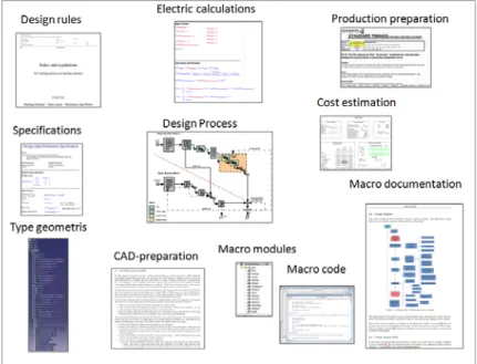
5.1 Collecting knowledge and Information
Collecting knowledge and information is one of the most important steps on do-ing documentation of DA system. At first, we need to figure out what kinds of knowledge do we have totally in DA system. Basically, the DA system has been developed and supported by large amount of knowledge which is filed in a differ-rent way with its unique role to the whole system. These supportive files are De-sign Rules, Specification, Type Geometry, Electric Calculation, DeDe-sign Process, CAD preparation, Macro modules, Macro code, Macro documentation, Produc-tion PreparaProduc-tion and Cost estimaProduc-tion, See Figure 5-1.
![Figure 1-10 Company Development process, information and repositories[4]](https://thumb-eu.123doks.com/thumbv2/5dokorg/5569580.145512/11.892.240.654.393.706/figure-company-development-process-information-repositories.webp)
![Figure 4-3 Example of rationale as depicted on any SysML diagram [26]](https://thumb-eu.123doks.com/thumbv2/5dokorg/5569580.145512/27.892.260.630.330.840/figure-example-rationale-depicted-sysml-diagram.webp)
![Figure 4-8 The default meta-classes for the MML view structure [31]](https://thumb-eu.123doks.com/thumbv2/5dokorg/5569580.145512/30.892.188.708.111.402/figure-default-meta-classes-mml-view-structure.webp)
![Figure 4-11 Illustration of 4 steps in DRed [29]](https://thumb-eu.123doks.com/thumbv2/5dokorg/5569580.145512/34.892.165.738.738.1068/figure-illustration-steps-dred.webp)
![Figure 4-12 Example of various tools used [32]](https://thumb-eu.123doks.com/thumbv2/5dokorg/5569580.145512/36.892.151.744.275.584/figure-example-various-tools-used.webp)
![Figure 4-13 Workspace of PMM [37]](https://thumb-eu.123doks.com/thumbv2/5dokorg/5569580.145512/37.892.251.645.810.1108/figure-workspace-of-pmm.webp)
![Figure 4-14 Class Information Cards and Product Explorer of PMM [37]](https://thumb-eu.123doks.com/thumbv2/5dokorg/5569580.145512/38.892.193.703.358.747/figure-class-information-cards-product-explorer-pmm.webp)
![Figure 5-1 some knowledge object in DA system[by Elgh, F.]](https://thumb-eu.123doks.com/thumbv2/5dokorg/5569580.145512/40.892.212.681.713.1075/figure-knowledge-object-da-elgh-f.webp)
![Figure 5-3 System process flow from Analysed DSM [by Elgh, F.]](https://thumb-eu.123doks.com/thumbv2/5dokorg/5569580.145512/42.892.201.693.181.519/figure-process-flow-analysed-dsm-elgh-f.webp)
