Department of Biology
and Chemical Engineering
Box 325, 631 05 Eskilstuna
Naphthyridine Based
Molecular Switches
Jhonny Wiik
Degree Project, ECTS 75p
At Mälardalen University
Eskilstuna 2012
Supervisor: Assoc. Prof. Simon Dunne
Examiner: Sven Hamp
Abstract
This thesis is focused on the synthesis and halogenation of 1,5-naphthyridine and 2,6-naphthyridine with the aim of finding a suitable method to synthesize mono- and bis-naphthyridine centered tridentate ligands for ruthenium complexes. Firstly the halogenated naphthyridines were synthesized, then 2-(2-thienyl)-6-tributylstannylpyridine was synthesized, and the two building blocks were coupled through a Stille cross coupling reaction.
The thesis describes the synthesis of 2,6-dichloro-naphthyridine, 2-chloro-naphthyridine, 1,5-dichloro-2,6-naphthyridine and 1-chloro-2,6-naphthyridine. The synthesis of many of the halogenated naphthyridines have previously been reported, with the exception of 1,5-dichloro-2,6-naphthyridine and some of its intermediates which, at present, to the best of the authors knowledge , has not been reported. Three strategies have been successfully tested for the synthesis of 1,5-dichloro-2,6-naphthyridine.
Secondly the thesis describes the synthesis of 2-(2-thienyl)-6-tributylstannylpyridine. The method of choice for synthesizing this Stille reagent was a Negishi coupling between 2-bromo-6-tributylstannylpyridine and 2-thiophenyl zinc chloride.
Thirdly the thesis describes a method for the synthesis of bis-2,6-(2-(2-thienyl)6-pyridinyl)-1,5-naphthyridine through a Stille cross-coupling.
“If we knew what it was we were doing, it would not be called research, would it?” Albert Einstein 1879-1955
Contents
Abstract ... 1 Abbreviation ... 5 Introduction ... 6 1.0 Electronics ... 6 1.1 The transistor ... 6 1.2 Moore’s law ... 81.3 Limitations of small components ... 8
1.4 Current solutions and things yet to come ... 9
1.5 Molecular electronics ... 10
1.6 What use would molecular electronics serve now? ... 10
1.7 The future - the perfect molecular device ... 10
Background ... 11
2.1 Donor Bridge Acceptor ... 11
2.2 The naphthyridines – an introduction ... 14
3.0 General methods and mechanisms ... 16
3.1 The Skraup reaction ... 16
3.2 Leimgruber-Batcho synthesis ... 17 3.3 Negishi cross-coupling ... 18 3.4 Stille Cross-coupling ... 19 4.0 The Project ... 20 4.1 Project origin ... 20 4.2 Project goal ... 20 5.0 Naphthyridine core for a reversible mono‐ and double‐cyclometallated switch. ... 22
5.1 Synthesis of mono- and bis-1,5-naphthyridine core. ... 22
5.2 Synthesis of mono- and bis-2,6-naphthyridine core. ... 25
Results ... 30 Discussions ... 32 Future work ... 34 Experimental ... 35 1,5-Naphthyridine (1) ... 35 1-Methyl-1,5-naphthyridine iodide (2) ... 35 1-Methyl-1,5-naphthyridine-2-one (3) ... 35 1-Chloro-1,5-naphthyridine (4) ... 35 1,5-Dimethyl-1,5-naphthyridine-2-one iodide (5) ... 36 1,5-Dimethyl-1,5-naphthyridine-2,6-dione (6) ... 36 2,5-Dichloro-1,5-naphthyridine (7) ... 36 3-Diethylisonicotinonitrile (9) ... 36 3-(2-(Dimethylamino)vinyl)isonicotinonitrile (10) ... 37 2,6-Naphthyridin-1(2H)-one (11) ... 37 6-Methyl-2,6-naphthyridin-1(2H)-one iodide (13)... 37 2-Methyl-2,6-naphthyridin-1,5(2H)-dione (14) ... 37 2,6-Dimethyl-2,6-naphthyridin-5-one iodide (18) ... 38 2,6-Dimethyl-2,6-naphthyridine-1,5-dione (19) ... 38 1,5-Dichloro-2,6-naphthyridine (17) ... 38 1-Chloro-2,6-naphthyridine (12) ... 38 1-Chloro-2-methyl-2,6-naphthyridine iodide (15) ... 39 1-Chloro-2-methyl-2,6-naphthyridine-5-one (16) ... 39 1,5-Dichloro-2,6-naphthyridine (17) ... 39 2,6-Bis(2-(thiophen-2-yl)6-pyridinyl)-1,5-naphthyridine (L2) ... 39 Acknowledgments ... 41 References ... 42 Attachments ... 45
Abbreviation
AcOH acetic acid Ar aryl bpy bipyridine Bu butyl CHCl3 chloroform COSY correlated spectroscopy DBA donor bridge acceptor DMF dimethyl formamide DMFDMA dimethyl formamide dimethyl acetal DMSO dimethyl sulfoxide ENIAC electronic numerical integrator and calculator Et ethyl EtOAc ethyl acetate EtOH ethanol HOMO highest occupied molecular orbital IC integrated circuit isc intersystem crossing LDA lithium diisopropylamide LED light emitting diode LUMO lowest unoccupied molecular orbital MCLF metal‐centered ligand field Me methyl MeOH methanol MLCT metal‐to‐ligand charge transfer n‐BuLi n‐Butyl lithium naph naphthyridine NOE nuclear overhauser effect Ph phenyl ppy phenylpyridine py pyridine r.t. room temperature RB round bottomed THF tetrahydrofuran TLC thin layer chromatography tpp 2,3,5,6‐tetrakis(2‐pyridyl)pyrazine tpy 2,2’:6’,2’’‐terpyridineIntroduction
1.0 Electronics
Today electronic equipment is used for almost anything and everything; we have become so accustomed to having electronic devices around us that we hardly notice them, from listening to music, driving our car or paying for groceries. They work in silence, doing our bidding, billions of tiny electronic components sending signals all over the world in a blink of an eye. The ever increasing demand for faster, cheaper and more efficient electronic devices has driven the electronics industry to constantly increase the number of electronic components in a device through miniaturization. This has consequently lead to more demanding manufacturing and testing processes, which in turn makes the
manufacturing process more expensive,even though the individual component in an IC chip is cheaper
due to size reduction.1,2
1.1 The transistor
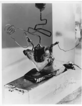
Since the birth of the transistor in 1947 (Figure 1) the evolution in electronic circuit technology has progressed exponentially. The first computer ENIAC was composed of about 18 000 vacuum tubes, 6 000 manual switches, 7 200 diodes, 70 000 resistors and 10 000 capacitors.3 ENIAC consumed about
150 kW of power, weighed around 27 tons and was not more powerful than today’s standard pocket
calculator.4 About half of the operation time was downtime because of burnt out vacuum tubes that
needed to be replaced and the longest operational interval ever made with ENIAC was 120 hours.5
Still at the time it was at least 1000 times faster than the present electromechanical machines and the
leap in computer power in a single machine has probably not been matched since.6 Computer science
and computer power continued to grown exponentially much thanks to the invention of the transistor.7 The transistor was first assembled by William Shockley, John Bardeen and Walter Brattain in 1947 at Bell laboratories.8 1 L. Ali, R. Sidek, I. Aris, M. A. M. Ali, B. S. Suparjo, “Design of a low cost IC tester”, American Journal of Applied Science, April 2005. 2 P. Packan, Science, 1999, 24, 2079. 3 R. Rojas, U. Hashagen, “The First Computers: Historty and Architectures”, 2000, ISBN:0262181975. 4 S. Johri, “Computer Programing and Operating Guide”, 2001, ISBN:8171827764; J. D. Dumas II, “Computer Architecture: Fundametals and Principles of Computer Design”, 2006, ISBN:0849327490. 5 P. Edwards, B. Broadwell, “Data Processing: Cumputers in Action”, 1979, ISBN:0534006159. 6 H. H. Goldstine, “The Computer: From Pascal To Von Neumann”, 1980, ISBN:0691023670. 7 G. Joubert, W. Nagel, F. Peters, “Parallel Computing: Software Technology, Algorithms, Architectures & Applications”, 2004, ISBN:0444516891. 8 H. R. Huff, U. Gösele, H. Tsuya. “Semi conductor: Silicon 1998”, 1998, ISBN:1566771935; G. McFarland, “Microprocessor Design”, 2006 , ISBN:0071459510.
Figure 1. A picture of the first transistor invented by Shockley, Bardeen and Brattain at Bell Labs, 1947. Image courtesy of Computer History Museum.
It was soon discovered to be a remarkable invention without any moving parts, low power
consumption and robust, the transistor overwhelmed the world. It had so many benefits compared to
the vacuum tube; in terms of reliability, price, speed and size that it quickly started to replace the vacuum tube. From the transistor radio in 1948 to the IBM personal computer in 1979, components that previously had been individually assembled on circuit boards were becoming too crowded and had to be integrated into small chips. In 1958 Jack Kilby createdthe firstintegrated circuit made from
germanium, six months later, Robert Noyce reported a similar device made out of silicon,9 and the
integrated circuit was born. To integrate several electronic components in one chip was soon found to be cheaper, less power consuming and more space efficient. From the Intel 8086 processor in 1978
containing 29 000 transistors to today’s top Intel processor, contain approximately two billion
transistors, the increase in transistors is staggering.10 No other invention has made such a progress in
size, speed and value than the transistor. Gordon Moore said that: “if the automobile industry had
experienced the same rhythm (as the semi-conductor industry), cars would drive one million kilometers in one hour, with barely more than one fuel tank, and it would cost less to throw away your car than to pay your parking ticket”.11 Many things would never have been possible if it was not for
the transistor, for instance flying to the moon, solving complex equations, predicting the weather or watching a movie on a cellular phone. It is truly a remarkable invention which has and will continue to change the world.
9 Jack Kilby and Robert Noyce are both co‐inventors of the integrated circuit. 10 B. DavIs, Intel Server Update, May 26 2009.
11 Organization for Economic Cooperate, “21st Century Technologies: Promises and Perils of a Dynamic Future”,
1.2 Moore’s law
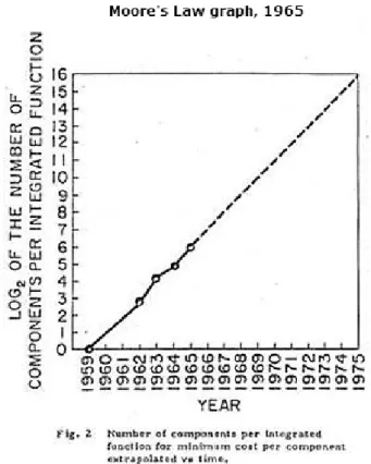
Co-founder, retired chairman and CEO of Intel Corporation, Gordon E. Moore, predicted in 1965 that the number of components on a computer chip would double every year, which become known as
Moore’s law (Figure 2). 12 In 1975 Moore updated his prediction to once every two years and the
industry has managed to follow Moore’s law till present day.13 But this exponential increase cannot go on ad infinitum.
Figure 2. Moore’s graph from his paper in 1965 where he predicted the exponential increase of components on a single computer chip.
1.3 Limitations of small components
The integrated circuit industry is continually shrinking and packing components more densely as
predicted by Moore’s law. Today there exist microprocessors with over two billion transistors which
occupy a few cm2.4 One could ask the question: “How small can one make an electronic component?”
It will eventually come down to the physical limitation of the materials used.14 As the size of the
integrated circuits gets smaller and smaller, effects such as quantum tunneling, hot electron effects and short channel effects have become a significant problem.14 Short channel effects arise from making the
width of the gate smaller, making the depleted areas on the source and drain on a transistor a large part of the total charge under the gate, leaving less charge to be depleted by the gate which lowers the threshold voltage. The short channel effect brings uncertainty to which threshold value and the signal
12 G. Moore, Electronics, April 19 1965, Vol 38, Nr 8.
13 G. Moore, Electron Device Meeting 1975 Internal, 1975, 11‐13. 14 R. W. Keyes, Rep. Prog. Phys. 2005, 68, 2701‐2746.
amplitude to turn transistors on and off.15 If the driver current is high and the gate length too short the
electric field can create a hot electron which can be trapped in the oxide insulation which can compromise and degenerate the transistor.16 Gate oxide thickness has been scaled down linearly with
the length of the transistor which also has reduced the short channel effects.14 But as the gate insulation
get thinner the effects of electron tunneling increase rapidly and even when the drain is not drawing current, the power supplied from the gate tunneling leakage causes additional heat that must be
removed.14 As the components in integrated circuits get smaller and the circuit density increases,
power dissipation per unit area increases.14 To reduce dynamic power, supply voltage has been scaled down which reduces the driver current which consequently reduces circuit speed. To circumvent reduction in speed in integrated circuits, voltage threshold has been scaled down with supply voltage which also has contributed to additional increase of static power. By reducing voltage threshold and thickness of gate insulation, speed and drive current has been preserved and smaller transistors achieved, but at the expense of increased power dissipation. Due to increased power dissipation in integrated circuits, excess thermal energy must be controlled since temperature has a significant impact on the reliability and performance of integrated circuits and can have devastating consequences if not properly treated.17
1.4 Current solutions and things yet to come
To solve the problem with electron tunneling a new gate insulation abbreviated as high-K, with a better dielectric properties, which can allow Moore’s law to continue for another decade or so. Intel uses hafnium-based insulation on their 32nm technology processors.
Why should we continue to try to follow Moore’s law? It is technological progresses that will help in continuing to evolve and make progress at a steady pace. It should not limit us from expanding and evolving the understanding of the universe just because we have reached a limitation of a certain technology. The smallest known switchlike device would be a quantum based switch; to use the electron spin as a memory or state. It is not possible with today’s knowledge and technology to utilize such a device. Molecules as components though? There already exist molecules that can mimic all electronic components, switches, insulators, wires, LEDs and so on.18 In comparison with a two billion transistor microprocessor which uses an area of a few cm2, if instead of a silicone based transistor a
molecule would be used as a switch with an average length of 1-3 nm; one would be able to fit approximately 1014 components per cm2.19 The sheer number of components is impressive.
15 C‐T. Sah, “Fundametals Of Solid‐State Electronics”, 1993, ISBN:9810206380. 16 N. Balkan. “Hot Electrons In Semiconductors: Physics and Devices”, 1998, ISBN:0198500580. 17 L. Scheffer, L. Lavagno, G. E. Martin, “EDA for IC Implementation, Circuit Design and Process Technology”, 2006, ISBN:9780849379246. 18 A. Nitzan, Annu. Rev. Phys. Chem. 2001, (52), 681; V.Mujica, M.A.Ratner, “Handbook of Nanoscience, Engineering, and Technology”; W. A. Goddard III et al., eds., CRC Press, 2002, Boca Raton, Fla; C. Joachim, J. K. Gimzewski, A. Aviram, Nature, 2000, (408), 541. 19 J. M. Tour, “Molecular Electronics: Commercial Insights, Chemistry, Devices, Architecture and Programming”, 2003, World Scientific Publishing, ISBN:9812382690.
1.5 Molecular electronics
The big problem in molecular electronics comes down to its small size, which is also one of its
beneficial properties.20 In a microprocessor every transistor is addressable and connected to a power
supply which would be impossible to do with a molecular device in a cheap and beneficial way, especially to utilize the size advantages. But the incredible potential in size, quantity and speed that such a device could have is worth the effort of pursuing the quest of making such technology a reality. There are still problems to be solved such as purity in synthetic applications, assembly and molecular device reliability.
1.6 What use would molecular electronics serve now?
The first step would be to integrate molecular devices into today’s silicone based electronics, and eventually replace silicone-based electronics with molecular electronics. This replacement of silicon based electronics is bound to be highly restricted due to the fact that giant supercompanies would not accept their own market being compromised. But then again, what would be gained from starting a competitive market in an already well established market with almost unlimited resources in comparison? It is more likely that supporting molecular electronics for the traditional integrated system will have a good way of finding its way out on the market with the support of giant electronic companies. In fact “replacement” would likely take place with passive components such as replacing metal wires with nano-tubes or complement the structure/insulation of a traditional transistor which in the end would not change the final product, more than perhaps assisting the device.It would be foolish to utilize molecular electronics without the use of existing electronic technology. There is much to gain from using an already well established technology which would give molecular devices an excellent platform to evolve on, both in economic and efficiency sense. It will most likely be the economic aspect which will drive molecular electronics technology forward.
1.7 The future - the perfect molecular device
So what would a perfect molecular device look like and how would it work? One molecule built from molecular building blocks, where individual electrons each have a specific purpose? Solar powered
nanobots able to repair individual cells? A pocket-sized supercomputer?21 Such a technology would
give incredible speed and almost unlimited amounts of components at immediate disposal. There would be incrediblepotential for such devices. Even though such devices aremore science fiction than reality at present, without great effort, numerous scientific breakthroughs, unimaginable amounts of money and man-hours. Perhaps one day it could become a reality, time will eventually tell.
20 R. L. Carroll, C. B. Gorman, Angew. Chem. Int. Ed. 2002, (41), 4378‐4400.
Background
2.1 Donor Bridge Acceptor
2.1.1 Energy and electron transfer
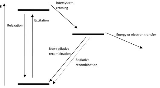
The donor bridge acceptor (DBA) theory consists of an electron donor, which can transfer energy or electrons, through a bridge to an electron acceptor or through space to another molecule, a quencher, described below using a Jablonski diagram (Figure 3). Before energy or an electron transfer can occur, an electron must be excited to a higher energy state of the donor. From this excited state several things can happen, for example the electron relaxes back to the ground state which is usually the mechanism for fluorescence. The excited electron can also go through an intersystem conversion to a lower energy state and from this state it can relax to the ground state either by radiative recombination which is usually the mechanism for phosphorescence, non-radiative recombination or participate in an electron
transfer process.22 There are some important qualities that a DBA system should have. The excited
state must last long enough for energy or an electron transfer to occur, which is why long emission lifetime is important. The longer emission lifetime the larger the chance for energy or electron transfer to occur. The molecule should be planar, as angle mismatch and poor orbital overlap complicates electron transfer. The bridge must be a good electron carrier, not requiring too much energy for electrons to flow nor acting as an electron sink.
Figure 3: A generalized Jablonski diagram for energy transformation.
22 B. L. Feringa, “Molecular Switches”, 2001, ISBN:3527299653. Relaxation Excitation Intersystem crossing Non‐radiative recombination Radiative recombination Energy or electron transfer E
2.1.2 Ruthenium polypyridyl complexes
Ruthenium can form octahedral d6 metal complexes such as ruthenium bis-terpyridine [Ru(tpy)
2]2+ and
ruthenium tris-bipyridine [Ru(bpy)3]2+ (Figure 4).
N N N N N N Ru N N N N N N Ru 2+ 2+
Figure 4. [Ru(tpy)2]2+ (left), and [Ru(bpy)3]2+ (right).
[Ru(bpy)3]2+ is photostable and has a long emission lifetime at room temperature and can undergo
energy and electron transfer processes. As shown in figure 5, the excited [Ru(bpy)3]2+ can fluorescence
back to the ground state via a metal to ligand charged transfer (1MLCT). However it is more common
for a d6 metal complex to decay through an intersystem crossing (k
isc) to a 3MLCT state. The decay
from 1MLCT to 3MLCT is enhanced by a heavy atom effect which enhances spin orbit coupling,
especially for such heavy metal core as ruthenium. From the 3MLCT state the decay to ground state
can occur through non-radiative (knr) or radiative (kr) decay (phosphorescence). Both the decays from 1MLCT to 3MLCT and from 1MLCT to ground state are spin-forbidden since it is only allowed for an
energy state with a certain multiplicity to lower its energy to a state with the same multiplicity. However for metal complexes, especially with heavy metal cores, the spin-selection rule does not apply since there is no pure singlet or triplet state, but a mixture of these characters which partially
allows these transitions.23 The 3MLCT state can also participate in energy or electron transfer
processes or be thermally excited to a metal centered ligand field (3MCLF) energy state (k
therm), which
very quickly decays via the non-radiative pathway (knr’) to the ground state.24 The 3MCLF is an
anti-bonding metal orbital which breaks the octahedral symmetry and leads to a very fast non-radiative decay.25 23 J. N. Demas, J.Chem. Educ, 1983, (60), 803 24 (a) K. Kalyanasundarma, ”Photochemistry of Polypyridine and Porphyrin Complexes”, 1992, ISBN:0123949920; (b) V. Balzani, G. Bergiminia, F. Marchionia, P. Ceronia, Coord. Chem. Rev, 2006, 1254; (c) A. Jjuris, V. Balzani, F. Barigelletti, S. Campagna, P. Belser, A. Von Zelewsky, Coord. Chem. Rev. 1988, 85. 25 (a) J. R. Kirchoff, D. R. McMillin, P. A. Marnot, J. P. Sauvage, J. Am. Chem. Soc. 1985, (107), 1138; (b) C. R. Hecker, P. E. Fanwick, D. R. McMillin, Inorg. Chem. 1991, (30), 659; (c) C. A. Bessel, R. F. See, D. L. Jameson, M. R. Churchill, K. J. Takeuchi, J. Chem. Soc. 1992, 3223; (d) E. C. Constable, A. M. W. C. Thompson, D. A. Tocher, M. A. M. Daniels, New J. Chem. 1992, (16), 855; (e) R. Steen, Licentiate Thesis, 2007, ISBN:9789185485550;
Figure 5. Jablonski diagram for a typical d6 metal complex.
The [Ru(tpy)2]2+ complex is unlike [Ru(bpy)3]2+ in several ways, it has a short excited state lifetime
and poor emission properties. The tridentate terpyridine ligand coordination around the metal center creates strain on the bite angle of the complex. This steric strain lowers the energy gap between
3MLCT and 3MCLF which at room temperature becomes easily thermally accessible.
Other benefits of using tpy instead of bpy ligands in metal complexes are that tpy complexes are
achiral when using tpy or symmetrical substituted tpy ligands. [M(bpy)3] complexes are chiral and
possess R (Δ) or S (Λ) enantiomers, which in a multi-nuclear system leads to time consuming separation procedures and potentially loss of half the product in every step if specific reaction conditions and reagents are not used to synthesize isomerically pure compounds.26
Petersen et.al27 and Thumel et.al28 showed that when using 2,3,5,6-tetrakis-(2-pyridyl)-pyrazine29 (tpp,
Figure 6) as a bridging ligand for a bimetallic terpyridine complex [(tpy)Ru(tpp)Ru(tpy)](PF6)4 or a
complementary ligand with terpyridine as a monometallic complex [(tpy)Ru(tpp)](PF6)2, the emission
lifetime was increased to 30 ns (×120) for the monometallic complex30 and 100 ns (×400) for the
bimetallic complex.15 This was a significant improvement compared to the [Ru(tpy)2]2+ complex
which at ambient temperature has a lifetime of 0.25 ns.12 This indicates that the energy level for the
HOMO orbital on tpp, compared to tpy, lowered the energy of tpp π* orbital and the corresponding
3MLCT state, increased the energy gap between 3MLCT and 3MCLF, thereby reducing the thermal
accessibility. It has also been showed that even though the bimetallic complex is symmetrical, the two metal centers give rise to two different oxidation states, which suggests that when one metal center is oxidized the second metal center pulls electron density from the bridging ligand, suggesting good 26 E. C. Constable, Chem. Soc. Rev. 2007, (36), 246. 27 J. D. Petersen, Supramolecular Photochemistry, 1987, 135. 28 R. P. Thummel, S. Chirayil, Inorg. Chim. Acta, 1988, (154), 77. 29 H. A. Goodwin, F. J. Lions, J. Am. Chem. Soc. 1959, (81), 6415. 30 L. M. Vogler, B. Scott, K. J. Brewer, Inorg. Chem. 1993, (32), 898. 1 MLCT 3 MLCT kisc kr Energy or electron transfer [Ru(bpy)3] 2+ E knr knr’ 3 MCLF Ktherm
metal-to-metal electronic interaction between the metal centers within the binuclear complexes. It might be fully possible to create a good functional bimetallic DBA system using tpy with a tridentate bridging ligand if the HOMO orbital for the bridging ligand increases the energy difference between the 3MLCT and 3MCLF states and might be well suitable to work as a single or double metal-centered
DBA system or switch.13
Figure 6. 2,3,5,6-tetrakis-(2-pyridyl)-pyrazine (tpp)
2.2 The naphthyridines – an introduction
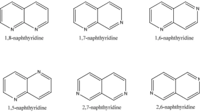
The first naphthyridine derivative was obtained and named by Arnold Reissert 1893 as the pyridine-like analogue to naphthalene.31 There are six different naphthyridines which are defined through the position of the nitrogens in the bicyclic system (Figure 7).
Figure 7. The six different naphthyridines.
The first unsubstituted naphthyridines synthesized, 1,5-naphthyridine32 and 1,8-naphthyridine33, were
published 1927 by Bobranski, Suchard and Koller. 1,6-Naphthyridine, 1,7-naphthyridine and
2,7-naphthyridine were reported by Ikekawa in 1958.34 2,6-Naphthyridine was independently reported by
Gicacomello et.al and Tan et.al in 1965.35 The naphthyridines and their derivatives have shown very
broad biological activities (Figure 8).
31 A. Reissert, Berichte, 1893, (26), 2137. 32 B. Bobranski, E. Sucharda, Berichte, 1927, (60), 1081. 33 G. Koller, Berichte, 1927, (60), 1918. 34 N. Ikekawa, Chem. Pharm. Bull. 1958, (6), 263; 269; 401;. 35 G. Giacomello, F. Gualteri, F. M. Ricceri, M. L. Stein, Tetrahedron Lett., 1965, 1117.; R. Tan, A.Taurins, Tetrahedron Lett. 1965, 2737.
N N Me COOH Et O Nalidixic acid Strong antibacterial N-(5-Fluorobenzyl)-4-hydroxy-2-oxo-1,2-dihydro-1,5-naphthyridine-3-carboxamide
Inhibits HIV integrase and HIV replicant
H N N O H N O OH F Benzo[c][1,6]naphthyridine Derivatives for male impotence and female sexual dysfunction
N N N N C5H11 C5H11 OH OH OH HO 5-(1,2-Dihydroxyethyl)-3,4-dihydroxy-1,7-dipentyl-1,2,3,4-tetrahydro-1,7-naphthyridin-7-ium Antidiabetic drug N N OMe Cl Cl 1,6Dichloro3methoxy8,9dihydro7H -benzo[de][2,7]naphthyridine
Treathment of asthma and lowering blood pressure
Figure 8: Examples of naphthyridine derivatives and their biological effects.
1,8-Naphthyridine is by far the most studied of the naphthyridine family, probably due to the discovery of the significant antibacterial properties associated with nalidixic acid. 1,8-Naphthyridine derivatives have gained increasing attention as ligands for metal coordinated complexes with a range of different metal ions such as Cu, Au, Zn. Mo, Re, Hg, Fe, Co, Ni, Ru, Rh, Pd, Pt, Eu and Tr (a more detailed description can be found in an excellent review by V.P.Litvinov). 36
Many naphthyridine derivatives show antibacterial properties, such as 1-methoxy-4,5,9,10-tetrahydropyrido[3,2,1] [1,6]naphthyridin-6(8H)-one which have been found in the roots of several plants and trees belonging to the genus Sophora (Figure 9).36
Figure 9. The Pagoda tree, Stryphonolobium japonicum (left); 1-Methoxy-4,5,9,10-tetrahydropyrido[3,2,1] [1,6]naphthyridin-6(8H)-one (right).
The 1,6-naphthyridine derivative which is found in the Pagoda tree lacks the ability to form symbioses with a nitrogen fixing bacteria called rhizobia on their roots. All parts of S. japonicum are commonly used in traditional Chinese medicine.37
36 V. P. Litvinov, Advances in Heterocyclic Chemistry, 2006, (91), 189‐300. 37 S. Li, S‐C. Li, P. Smith, “Chinese Medical Herbs: A Modern Edition of a Classic Sixteenth‐Century Manual”. 2003, ISBN:9780486428017. N N O OMe
3.0 General methods and mechanisms
3.1 The Skraup reaction
The Skraup reaction was published by Zdenko Hans Skraup in 1880 and is probably the most famous
reaction for quinoline synthesis.38 In a typical Skraup reaction, an aromatic amine, concentrated
sulfuric acid, glycerol and nitrobenzene are mixed together, in a large flask connected with a large condenser. When the reaction starts it usually undergoes a self-maintained reflux with large amounts of thermal energy released.39,40 The mechanism for the generation of quinolines under the conditions
of the Skraup reaction proposes that glycerol catalyzed by sulfuric acid produces acrolein as an intermediate which undergoes conjugated addition with the aromatic amine. The subsequent ring-closure and dehydration forms the 1,2-diydroquinoline. Nitrobenzene oxidizes the compound to the fully aromatic heterocycle (Scheme 1).
Scheme 1. Synthesis of quinoline through the Skraup synthesis.
The Skraup reaction is a very exothermic reaction, and it is not uncommon for thermal runaways to occur. Many variations of the Skraup synthesis have been developed, in attempts to improve yields. Reactions utilizing boric acid or other oxidizing agents such as arsenic acid, iron (III) salts, tin (IV) salts, various substituted nitrobenzenes or iodides have been reported.40,36
38 Z. H. Skraup, Berichte, 1880, (13), 2086.
39 S. A. Yamashkin, E. A. Oreshkina, Chemistry of Heterocyclic Compounds. Vol 42. No.6, 2006, 701. 40 Clayden, Greeves, Warren and Wothers, Organic Chemistry, Oxford University press, 2001, 1210‐1211.
The Skraup reaction can easily be adapted for synthesis of phenanthrolines and naphthyridines (Scheme 2),41,42 by using benzo-diamines or aminopyridines instead of anilines as for the synthesis of quinoline. N N NH2 NH2 H2SO4 Nitrobenzene 130oC OH OH HO
Scheme 2. The synthesis of 1,10-phenanthroline (above) and the synthesis of 1,5-naphthyridine (below) using the Skraup synthesis.
There is some debate regarding the mechanism and Denmark et. al. have suggested a
fragmentation-recombination mechanism based upon carbon isotope scrambling experiments.43
3.2 Leimgruber-Batcho synthesis
Leimgruber-Batcho synthesis is widely used for indoles (Scheme 3), the reaction is dependent on the acidity of a methyl group ortho to the aromatic nitro group, and also at the α or γ positions on a pyridine.
Scheme 3. Proposed Leimgruber-Batcho indole synthesis mechanism.
The mechanism is believed to involve ionization of dimethylformamide dimethyl acetal (DMFDMA), producing methoxide and an electrophilic component. Methoxide deprotonates the aromatic methyl group and the electrophilic component to give the enamine. Reduction of the nitro group leads to the indole.
For the 2,6-naphthyridine synthesis we have used a modified Leimgruber-Batcho reaction. Since the target is not indole, a nitrile is used as the ortho electron-withdrawing group. This will also serve as the point of ring-closure when reducing the enamine, giving 2,6-naphthyridine-1-one (Scheme 4).
41 P. N. W. Baxter, R. G. Khoury, J‐M. Lehn, G. Baum, D. Fenske, Chem. Eur. J. 2000, 6, (22), 4140‐4148. 42 Y. Hamada, I. Takeuchi, Chem. Pharm. Bull. 1971, 9, (19), 1857.
Scheme 4. Proposed Leimgruber-Batcho synthesis mechanism.
3.3 Negishi cross-coupling
The Negishi cross-coupling reaction is named after Ei-ichi Negishi and was published in 1977 as the first reaction for producing biaryls in good yields, catalyzed by nickel or palladium.44 The mechanism
begins by activating the palladium to Pd(0) followed by an oxidative addition of a organic halide. Transmetallation with the organic zinc halide gives the trans intermediate which isomerizes to the cis intermediate followed by a reductive elimination giving the newly coupled compound and Pd(0) (Scheme 5).
Scheme 5. Mechansim for the Negishi coupling reaction. L = ligands, R = alkenyl, aryl, allyl, benzyl, propargyl. R’ = akenyl, aryl, alkyl, benzyl, allyl. X = Cl, Br, I, (can also be triflates or acetyloxy for the organohalide).
Known side reactions, such as homocoupling and dehalogenation, have been reported (Scheme 6).45 It
is believed that a second transmetallation between the diarylpalladium and arylmetal halide is responsible for the homocoupling.
( )
HOZnX
ArH
O
H
ArZnX
Pd
Ar
Ar
PdAr
Ar
ArZnX
PdAr
Ar
ZnX
Ar
ArPdAr
+
→
+
+
→
+
→
+
20
'
'
'
'
'
'
'
'
Scheme 6. Top two rows show the homocoupling, which is the result of a second transmetalation reaction between the diarylmetal intermediate and arylmetal halide. Bottom row shows the dehalogenation.
In this thesis, the Negishi coupling has been used to couple an aromatic compound to a Stille reagent, 2-thiophenyl zinc chloride with 5-bromo-2-tributylstannyl-pyridine. The benefits of the Negishi
44 E. Negishi, O. King, N. Okukado, J. Org. Chem. 1977, 42 (10), 1821‐1823.
palladium-catalyzed reaction using a Stille halide reagent, like in this case, is selective towards the halide and does not affect the tributyltin substituent on the pyridine, making purification easier and increasing the yield.
3.4 Stille Cross-coupling
The Stille reaction is a very versatile cross-coupling reaction, with very few limitations. Even though alternatives are preferred due to the high toxicity of tin compounds, it is a well established and reliable reaction. It is similar to Negishi coupling (Scheme 7), but instead of the organozinc compound, an organotin compound is used. It is usually preferred to add a ligand stabilizing compound, such as copper iodide, to prevent poisoning of the palladium catalyst.
PdLn Pd L X L R Pd L R' L R Pd R R' L L 2L R-X R'SnR3'' XSnR3'' R-R' oxidative addition transmetalation trans/ cis isomerization reductive elimination
Scheme 7. Proposed mechanism for the Stille reaction.
In the first step of the catalytic cycle, the palladium catalyst is reduced to the active form Pd(0). Oxidative addition of an organohalide gives a cis intermediate which isomerizes quickly to the trans intermediate. Transmetalation with the organostannane gives a trans organopalladium intermediate with both components, which isomerizes to the cis intermediate. The complex undergoes a reductive elimination yielding the product and regenerating the active catalyst (Pd(0)) in the process.
In this thesis a procedure by G.C.Fu is used which can effectively utilize organochlorides in a Stille coupling through use of a catalyst mixture, tris(dibenzylidineacetone)dipalladium(0)/tris-tert-butylphosphonium tetrafluoroborate (1:2). The Stille cross-coupling has also been used as the last step to couple chlorinated naphthyridines with the stannyl reagent.
4.0 The Project
4.1 Project origin
The main interest is the creation of a reversible switch based on the principles developed by E. C.
Constable, D. G. F. Rees, S. J. Dunne and C. X. Schmitt (Scheme 8).46
The switch mechanism is
based on a binding mode change upon the thiophene unit, from being coordinated through the sulfur to the carbon, turning the thiophene 180 degrees, with a great change in redox potential. The use of a naphthyridine core for the molecular switches within this thesis is a continuation of the work from Simon J. Dunnes group, suggested by R. O. Steen.47
Scheme 8. Original switch developed by E. C. Constable and coworkers.
4.2 Project goal
The aim of the project was to create a series of symmetrical naphthyridine bridging ligands for mono
[(tpy)Ru(naph)]2+ and bimetallic ruthenium complexes [(tpy)Ru(naph)Ru(tpy)]4+. As described in
section 2.1, bimetallic complexes with metal-to-metal communication, in which the individually metal centers can be switched independently can serve as a prototype for a double centered and reversible switch.
The goal of the project was originally to synthesize 2,6-Bis(2-(thiophen-2-yl)6-pyridinyl)-1,5-naphthyridine as a bridging ligand for a [(tpy)Ru(th-pyr-naph-pyr-th)Ru(tpy)]4+ complex. The project
was eventually expanded to include bis- and mono-1,5-naphthyridine, 2,6-napthyridine and 2,7-naphthyridine cores (Figure 10). If enough time existed the project would also include the formation of the six ruthenium complexes in all switching states, yielding a total of 12-15 complexes, depending on if the double-metal centered cores could be switched independently. Eventually realizing that there would not be enough time to complete such a vast project within the time frame for one Masters student, it was decided to create as many different naphthyridine cores as possible. The method used for making the naphthyridine centered tridentate switch frame was through a modification of a previously reported procedure by Gregory C. Fu and was successfully used in synthesis of 2,6-bis-(6-thiophen-2-yl-pyridin-2-yl)-[1,5]naphthyridine. The work included the synthesis of mono- and double-
46 E. C. Constable, S. J. Dunne, D. G. F. Rees, C. X. Schmitt. Chem. Commun. 1996, 1169‐1170. 47 R.O. Steen, Licentiate Thesis, Mälardalen University Press, 77, 2007, ISBN:9789185485550.
chlorinated 1,5-naphthyridine and 2,6-naphthyridine, including the thienyl pyridine part of the
naphthyridine core.48 After several unsuccessful purifications attempts by chromatography The
synthesis of 2,7-naphthyridine had eventually be abandoned since there was not enough time to include the 2,7-naphthyridines to the project (se section 5.2).
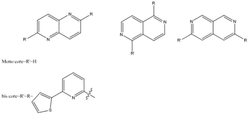
Figure 10. Bis and mono 6-thien-2-yl-pyridin-2-yl-naphthyridines.
5.0 Naphthyridine core for a reversible mono‐ and double‐cyclometallated
switch.
5.1 Synthesis of mono- and bis-1,5-naphthyridine core.
1,5-Naphthyridine was synthesized utilizing the Skraup reaction (Scheme 9). It was found that a method of continuous extraction with hexane, at reflux, on the neutralized reaction product gave the naphthyridine with sufficient purity in an average yield of 40%. Small amounts were recrystallized for analysis, 20% yield. When comparing extracted naphthyridine with the recrystallized naphthyridine
there was no discernable difference in 1H NMR, TLC or yield from the following steps. The only
difference found was that the continually extracted naphthyridine was somewhat more yellow than the recrystallized, but over time the recrystallized naphthyridine turned yellow. After long term storage the
naphthyridine turned brown. 1H NMR showed no difference between the older brown and newly
recrystallized naphthyridines besides a larger water peak indicating that the compound was hygroscopic.
N N
N NH2
i)H2SO4
Na nitrobenzenesulf onic acid salt FeSO4*7H2O
H3BO3
0-5oC
ii)glycerol 135oC 4.5h
Scheme 9. Skraup synthesis.
In order to synthesize the 2,6-bis-(6-thiophen-2-yl-pyridin-2-yl)-[1,5]naphthyridine a Stille cross-coupling was proposed for linking the thienylpyridine with the naphthyridine. POCl3 was the halogen
donor of choice, due to the high cost of its brominated counterpart (POBr3).
2,6-Dichloro-1,5-naphthyridine was to be coupled with 2-thiophen-2-yl-6-tributylstannylpyridine.33 The first approach
was to prepare the naphthyridine in its mono and bis N-oxide form and then halogenate by heating in
the presence of POCl3 (Scheme 10). The latter step has been previously reported by George R.
Newkome et.al.49
Scheme 10. Newkomes method (first row) for making bis-chlorinated naphthyridines.
After several attempts at purifying the naphthyridine N-oxides and the resultant halogenated naphthyridines, the method was abandoned, since the yields were extremely low (less than 1.5 % after two steps). Another approach was conceived, a similar approach to that used by R. Steen in his phenanthroline synthesis (Scheme 11).47
Scheme 11. Synthetic route for 4,7-dimethyl-4,7-dihydro-[4,7]phenanthroline-3,8-dione.
The first step was preparation of the N-methylated iodide salt (2) followed by an oxidative hydrolysis (3), which can be repeated once more to yield the dione (6) for the bis chlorinated naphthyridine (7), and finally halogenation (4 and 7, Scheme 12). In an attempt to increase final yields raw products from the initial steps were carried through to the final step with good results. The only obstacle found was if there was 1-methyl-1,5-naphthyridin-2-one (3) present with 1,5-dimethyl-1,5-naphthyridin-2,6-dione (6) when performing the chlorination step to give 2,6-dichloro-1,5-naphthyridine (7), it would sublime together with the dichloro naphthyridine. This could easily be avoided by pre-extracting the 1,5-dimethyl-1,5-naphthyridin-2,6-dione (6) with diethyl ether before extracting with chloroform to remove and recover any 1-methyl-1,5-naphthyridin-2-one (3) present.
N N MeI MeOH N N I K3Fe(CN)6(aq) NaOH(aq) N N O POCl3 PCl5 N N Cl K3Fe(CN)6(aq) NaOH(aq) MeI benzene N N O O POCl3 PCl5 N N Cl Cl 1 2 3 4 6 7
Scheme 12. Proposed pathway for 2-chloro-1,5-naphthyridine and 2,6-dichloro-1,5-naphthyridine.
The first Stille coupling reactions using mono and dichloro naphthyridines, using similar procedures as
described by G. C. Fu (Scheme 13),48 showed little or no coupling by H1 NMR spectroscopy. KF was
used instead of CsF when trying to couple the tin reagent with 2-chloro-1,5-naphthyridine and a mixture of starting materials and coupled products was obtained (approx 1:1).
N N Cl Cl N S Bu3Sn 1.5% Pd2(dba)3 3.0% [(t-Bu)3PH]BF4 2.2eq CsF N N N S N S 7 L2
Using KF and after 24 h reflux additional catalyst mixture was added and reflux was prolonged for an additional 24 h to give complete conversion of the starting material (7). H1 NMR data indicated that a single naphthyridine compound was present but with large amounts of tin butyl residues. The product
was almost completely insoluble in common deuterated solvents available (DMSO, THF, CHCl3,
acetonitrile, H2O, MeOH), which would be expected in a symmetrical ring system of this size, the H1
NMR data is somewhat inconclusive (Figure 11).
Figure 11. 1H NMR of bis-2,6-[6(thien-2-yl)-pyridin-2-yl]-1,5-naphthyridine in DMSO (full NMR data can be found in appendix).
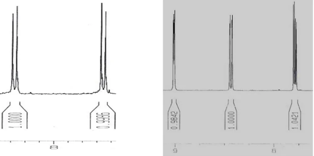
Since the products could be a unreacted, dehalogenated or coupled naphthyridine H1 NMR spectra of
2,6-dichloro-1,5-naphthyridine and 1,5-naphthyridine were compared with that of the product but no match was found (Figure 12). Comparison with the NMR data and the insolubility of the compound
indicated that the product was the desired compound. To confirm the identity of the compound by 1H
NMR spectroscopy, the [(tpy)Ru(naph)Ru(tpy)](PF6)4 complex must be synthesized in order to
increase solubility.
Figure 12. 1H NMR of 2,6-dichloro-1,5-naphthyridine to the left and 1,5-naphthyridine to the right in DMSO (full NMR data can be found in the appendix)
5.2 Synthesis of mono- and bis-2,6-naphthyridine core.
The original route for making 2,6-naphthyridine and 2,7-naphthyridine was via a previously reported procedure by Atsushi Numata et.al.50
Scheme 14. Original route for 2,6- and 2,7-naphthyridine (first step (A), lithiation with BuLi, and reacting the intermediate with LDA, yielding the aldehyde.
Purification using flash chromatography proved difficult as TLC revealed that there was a mixture of two compounds present at all times. After running several columns and finally a preparative TLC without success, the decision was made not to continue since the silicon reagent used in the following step was expensive and was only available in small quantities. It is believed that the aldehyde was oxidized to the acid through interaction with the silica in the column and preparative TLC plates, and at that time there was no clear way of circumventing this problem. The preparation of the 2,7-naphthyridine core was cancelled as time was running short. It might have been possible to deactivate silica with NEt3 or use basic aluminum oxide to avoid oxidization of the aldehyde.
The next approach was to use a Leimgruber-Batcho synthesis to get 2,6-naphthyridin-2-one. Firstly 3-picoline N-oxide (8) was activated with ethyl iodide and then reacted it with potassium cyanide to give 3-picoline-4-carbonitrile (9). The Leimgruber-Batcho synthesis was then performed by heating DMFDMA in DMF to yield the amino vinyl carbonitrile compound (10). Ring closure in aqueous HBr
yielded 2,6-naphthyridin-1(2H)-one (11). Finally halogenation by refluxing in POCl3 gave
1-chloro-2,6-naphthyridine (12) (Scheme 15).
Scheme 15. Leimgruber-Batcho synthesis for 2,6-naphthyridin-2-one
Focus was now put onto generating the dichloro-2,6-naphthyridine. Starting with the same approach as for 1,5-naphthyridine by N-alkylating with MeI to give 6-methyl-2,6-naphthyridine-1(2H)-one iodide
(13). Oxidative hydrolysis with NaOH and K3Fe(CN)6 yielded
6-methyl-2,6-naphthyridine-1,5(2H)-dione (14) but when trying to alkylate compound 11 with MeI, after several days of reflux in different
solvents, (MeOH, benzene and nitrobenzene) H1 NMR spectroscopy showed very slow conversion to
the target compound (Scheme 16).
Scheme 16. First attempt at acquiring the naphthyridine-dione derivative.
Since N-alkylation was not satisfactory using the current conditions with 2,6-naphthyridin-1(2H)-one (11), N-alkylation with 1-chloro-2,6-naphthyridine (12) was tested to achieve 5-chloro-2-methyl-2,6-naphthyridine iodide (15). After 24h reflux with MeI in benzene, 20% starting material remained by
H1 NMR spectroscopy. After an additional 24h reflux, 13% starting material was found and workup
was undertaken. Since there was a possibility that the alkylation could occur on either of the nitrogens, an NMR COSY analysis was made to confirm where the alkylation had occurred. It was found that the 6-nitrogen had been alkylated selectively.
N N Cl N N Cl N N Cl I I MeI 12 15
Scheme 17: Alkylation of 1-chloro-2,6-naphthyridine.
After evaporation and washing compound 15 with ether, oxidative hydrolysis with potassium hexacyanoferrate and sodium hydroxide yielded 5-chloro-2-methyl-2,6-naphthyridine-1-one (16) in
50% yield (1:1 starting material and product). Halogenation in POCl3 and PCl5 gave a mixture of
1,5-dichloro-2,6-naphthyridine (17) and other naphthyridine-like compounds (Scheme 18). H1 NMR
spectroscopy revealed multiple naphthyridine compounds.
Scheme 18. First attempt towards 1,5-dichloro-2,7-naphthyridine.
Since some of the N-methylated 2,6-naphthyridin-2(1H)-one was available from earlier experiments,
oxidative hydrolysis with NaOH and K3Fe(CN)6 was tested to give compound 14. The first attempt
gave no reaction. The second attempt under more watchful and careful conditions produced the dione.
deactivated towards this type of reaction. Reproducibility for this procedure was problematic. Using the 6-methyl-2,6-naphthyridin-1(2H)-one in the chlorination step to give compound 17 (Scheme 19),
yielded multiple aromatic compounds as shown by H1 NMR.
N NH O N NH O O I K3[Fe(CN)6] NaOH POClPCl53 N N Cl Cl 14 13 17
Scheme 19. Second route for 1,5-dichloro-2,6-naphthyridine.
The use of DMF as the solvent helped to optimize the alkylation of 2,6-naphthyridin-1(2H)-one, since the nature of the solvent (polar aprotic) assists SN2 type reactions. In a parallel experiment, K2CO3 was
tested to see if it could improve coordination of the N-alkylation (Scheme 20). Both reactions were complete after 24 h at reflux, and the precipitate could be easily collected from the DMF. After filtration and washing, a color difference in the two compounds was noted. The compound from the reaction using K2CO3 in the mixture was bright yellow while the other compound was more brownish.
After recrystallization of the two compounds, the compound from the reaction without K2CO3 turned
from pale to yellow to brown when exposed to air, while the other compound from the reaction using
K2CO3 remained stable when exposed to air. When analyzed by H1 NMR the compound synthesized
with K2CO3 present in the reaction, displayed two singlets in the aliphatic region and no N-H peak,
suggesting that there could have been a double alkylation (Scheme 20).
Scheme 20. Alkylation of 2,6-naphthyridin-2(1H)-one.
1D NOE difference and COSY confirmed that the double N-alkylation had occurred in the mixture using K2CO3 yielding 2,6-dimethyl-2,6-naphthyridine-1-one iodide (18). The potassium ion can help
in via coordination during the alkylation, and it seemed that K2CO3 sufficiently basic under these
reaction conditions to remove the acidic N-H proton and participate in an exchange reaction, as well as help in the N-alkylation step on the other nitrogen. Continuing oxidative hydrolysis with NaOH and K3Fe(CN)6 gave 2,6-dimethyl-2,6-naphthyridine-1,5-dione (19) in good yield.
The chlorination with POCl3 and PCl5 was tested and it revealed slow conversion to the dichloro
Scheme 21. The third route for preparing 1,5-dichloro-2,6-naphthyridine.
Phenylphosphonic dichloride was tested instead of using a mixture of POCl3 and PCl5 as the
chlorinating agent on 2,6-dimethyl-2,6-naphthyridine-1,6-dione (19). TLC showed one product and H1
5.3 2-(Thiophen-2-yl)-6-tributylstannylpyridine
For the synthesis of 2-(2-thiophen-2-yl)-6-tributylstannylpyridine the same method was used as described by R. Steen (Scheme 22).51
Scheme 22. The original design describing the formation of 2(2-thiophene)6-tributylstannylpyridine.
The Grignard coupling between 2,6-dibromopyridine and t-thiophenyl magnesium bromide did not work. When quenching the reaction after 24 h there was a violent reaction indicating that the Grignard
reagent was still active and had not coupled with 2,6-dibromo pyridine, which was confirmed by 1H
NMR spectroscopy. Several attempts using Grignard coupling and alternative methods such as Suzuki, Stille, Negishi, reversed and direct lithiation failed, which by trial and error indicated that there was something in the sample of 2,6-dibromo pyridine interfering with the reactions.
After recrystallization of 2,6-dibromopyridine from ethanol/ethyl acetate, a synthesis using a Negishi cross-coupling procedure was chosen as it had an easier workup procedure (Scheme 23).52 Despite the
fact that the use of excess tributylstannyl chloride led to tertbutyltin as a side product, it was easier to remove tertbutylstannane from the target compound, and even if not completely removed, tertbutylstannane was not likely to react or interfere in the Stille coupling.
Scheme 23. The chosen method for the synthesis of 2(2-thipohen-2-yl)6-tributylstannylpyridine.
The 2-bromo-6-tributylstannylpyridine was synthesized from recrystallized 2,6-dibromopyridine using 2.1 eq. n-BuLi followed by 1.1 eq. tributylstannyl chloride under argon at -60˚C followed by filtration and distillation using a kugelröhr apparatus (3 Torr, 133-138˚C for several hours).
The Negishi cross-coupling was performed by lithiation of 2-bromothiophene which was then reacted
with a solution of 1M ZnCl2 in ether at < -65˚C in THF under an argon atmosphere. The reaction
mixture was allowed to reach r.t. and tetrakis(triphenylphosphine)Pd(0) and 2-bromo-6-tributylstannyl
51 J. S. Field, R. J. Haines, E. I. Lakoba, M. H. Sosabowski, J. Chem .Soc. 2001, (1), 3352‐3360; O. Meth‐Cohn, H. Jiang, J. Chem. Soc. 1998, (1), 3737‐3745.
pyridine were added and the mixture was left to stir overnight. After standard workup (extraction, evaporation and drying) a dark red/yellow oil was obtained. The dark colour was probably due to from
zinc residues which were deemed not likely to interfere in any further reactions, 1H NMR
spectroscopy revealed the compound to be pure enough to be used without further purification.
Results
The results discussed in this section will be focused on final compounds synthesized. Ligand 2,6-Bis(2-(thiophen-2-yl)6-pyridinyl)-1,5-naphthyridine (L2), which was the only ligand synthesized, the halogenated naphthyridines 2-chloro-1,5-naphthyridine (4), 2,5-dichloro-1,5-naphthyridine (7), 1-chloro-2,6-naphthyridine (12) and 1,5-di1-chloro-2,6-naphthyridine (17). Details on the synthesis and details on the intermediates can be found in the Experimental section and NMR data in the appendix. The synthesis of 2,6-Bis(2-(thiophen-2-yl)6-pyridinyl)-1,5-naphthyridine (L2) resulted in a insoluble compound as described in section 5.1 (Figure 13).
Figure 13. 2,6-Bis(2-(thiophen-2-yl)6-pyridinyl)-1,5-naphthyridine (L2).
Since there were large amounts of tin butyl residues present neither yield nor representative weight could be presented. Final purifications steps were not done due to lack of time. Despite the compounds insolubility properties towards the deuterated solvents available an H1 NMR spectra, using deuterated
DMSO, was obtained (Figure 11). Though the large amount of tin residue present and the low concentration of the product in the NMR sample the NMR spectra still gives indications that the L2 ligand is the actual compound created. The integral of the peaks has the correct proportions to fit the amounts of protons for L2 as well as the structure of the peaks. Based on NMR spectras from 1,5-naphthyridine intermediate and NMR predictions the amount of protons and positions have been roughly estimated (Figure 15).
N N N S N S L2 A B C D E G F H
Figure 14. 1H NMR of bis-2,6-[6(thien-2-yl)-pyridin-2-yl]-1,5-naphthyridine, whit proton establishment and count.
Cause of the compounds insoluble nature no 2D NMR spectra could be preformed which could provide further proof that the compound analyzed indeed was L2, and also the positions of the protons would be confirmed. As stated in section 5.1 the Ru-complex would have to be synthesized in order to increase solubility, and with increased solubility get an enough concentrated NMR sample to run carbon and 2D NMR analysis.
L2 H1 NMR shows that none of the starting material, 2,6-dichloro-1,5-naphthyridine (7), nor the
dehalogenated naphthyridine, 1,5-naphthyridine (1), was present. Three likely scenarios of the Stille coupling reaction would be expected. 1. The Stille coupling worked as planed and L2 was sanitized. 2. Nothing had happened, which would have left the starting material intact. 3. Dehalogenation would have occurred leaving 1,5-naphthyridine. Since none starting material nor 1,5-naphthyridine was found supports the case that the L2 synthesis was successful.
The 2-chloro-1,5-naphthyridine (4) synthesis was synthesized with an total yield of 12% over 4 steps. The fact that the Skraup reaction in the first reaction gave 39% yield should be considered as a sacrificial beneficial reaction, since the 1,5-naphthyridine was available on the market but was 110 times more expensive than the 3-amino pyridine at the time. The overall yield compared from 1,5-naphthyridine is 32%. The yield from the halogenations step of 2-chloro-1,5-1,5-naphthyridine (4) was affected by the sublimation purification, which is known to have a lower yield, but instead the product purified with sublimation becomes very pure. TLC and NMR spectroscopy showed no evidence of any other compounds. It is estimated that the sublimated 2-chloro-1,5-naphthyridine that the purity of the compound should be well over 98%.
The 2,6-dichloro-1,5-naphthyridine (7) synthesis was synthesized with an total yield of 2% over 6 steps. The fact that the Skraup reaction in the first reaction gave 39% yield should be considered as a sacrificial beneficial reaction, since the 1,5-naphthyridine was available on the market but was 110 times more expensive than the 3-amino pyridine at the time as stated for the synthesis of chloro-1,5-naphthyridine (4). The overall yield compared from 1,5-chloro-1,5-naphthyridine is 6%. The yield from the
halogenations step of 2,6-dichloro-1,5-naphthyridine (7) was affected by the sublimation purification, which is known to have a lower yield, but instead the product purified with sublimation becomes very pure. TLC and NMR spectroscopy showed no evidence of any other compounds. It is estimated that the sublimated 2-chloro-1,5-naphthyridine that the purity of the compound should be well over 98%. The oxidative hydrolysis step was the yield lowering step with a yield of 19% over that one step. Unfortunately there was no time to optimize that step.
The 1-chloro-2,6-naphthyridine (12) synthesis was synthesized with an total yield of 32% over 4 steps. The 1-chloro-2,6-naphthyridine (12) showed high purity from TLC and NMR spectroscopy and showed no trace of other compounds. The purity of the compound should be over 95%.
The last of the halogenated naphthyridines, the 1,5-dichloro-2,6-naphthyridine, had a total yield of 39% over 6 steps. The 1-chloro-2,6-naphthyridine (17) showed high purity from TLC and NMR spectroscopy and showed no trace of other compounds. The purity of the compound should be over 95%.
Discussions
The synthetic work in this thesis primarily focuses on naphthyridine chemistry. Most work and research has been done on 1,5-naphthyridine and once the route shown in scheme 24 was established the synthetic work on 1,5-naphthyridine was straightforward with small difficulties and average to excellent yields in each step, for the exception of 1,5-dimethyl-1,5-naphthyridine-2,6-dione (6). The oxidative hydrolysis of 1,5-dimethyl-1,5-naphthyridine-2-one iodide (5) differed in several ways from all other naphthyridines. The solubility in water was poorer, even when heating the mixture the compound would not completely dissolve and once cooled again more would precipitate. A few important observations were made for the oxidative hydrolysis using potassium hexacyanoferrate and sodium hydroxide. Firstly the colder the reaction conditions were, the better the yield. Secondly, slower addition of potassium hexacyanoferrate and sodium hydroxide resulted in an increased yield. Thirdly, the solubility of the starting material seems to be an important factor for the reaction.
Scheme 24: Overview of mono and di-chloro-1,5-naphthyridines.
Several pathways towards 1,5-dichloro-2,6-naphthyridine have been investigated (Scheme 25). The upper pathway in scheme 24, compounds 11 to 16, presented no difficulties, except for the chlorination leading to 1,5-dichloro-2,6-napthyridine (17) with phosphorus oxychloride and
phosphorus pentachloride. It would seem that a competitive side reaction was in play, because the more product that was produced the more side product formed. The yield of the target compound peaked around 50-60% at best with an average of 2:1 starting material/side produkt. Prolonging the reaction for full conversion of the starting material gave more side reactions with a subsequent decrease in product yield.
N NH O N N Cl N NH O N N O POCl3 DMF MeI DMF MeI K2CO3 N N Cl N N Cl O N NH O N N O O O N N Cl Cl MeI benzene I I I K3[Fe(CN)6] NaOH K3[Fe(CN)6] NaOH K3[Fe(CN)6] NaOH POCl3 PCl5 POCl3 PCl5 Phenylphosphonic dichloride (94%) 11 12 15 16 13 14 18 19 17 59% 99% 63% 79%
77% over this and previous step
Scheme 25: Overview of the formation of 1,5-dichloro-2,6-naphthyridine.
Firstly compound 13 showed sensitivity towards aerial oxidation and also hygroscopic properties. Secondly the oxidative hydrolysis of compound 13 proved to be difficult. This could be due to the alkaline reaction conditions, which lead to deprotonation of the the N-H proton and deactivating the compound giving poor yield if any at all. Total pH control or completely different reaction conditions would be needed for synthesis of compound 14. Chlorination with phosphorus oxychloride and phosphorus pentachloride gave similar results as described for the upper pathway in scheme 24.
The bottom pathway in scheme 25 towards compounds 18 and 19, worked very well. Compound 18 showed good stability towards air. The chlorination with phosphorus oxychloride and phosphorus pentachloride gave similar results as for compounds 14 and 16. This was eventually solved using phenylphosphonic dichloride which gave the dichlorinated naphthyridine in excellent yield.
There was not enough time to optimize the oxidative hydrolysis for the synthesis of 1,5-dimethyl-1,5-naphthyridine-2,6-dione (6), nor was there any time to test chlorination with phenylphosphonic dichloride for compounds 14 and 16.
In summary, important advances in naphthyridine chemistry have been achieved. DMF proved to be an excellent solvent when alkylation proved difficult, for example compounds 13 and 18. Key conditions for the oxidative hydrolysis with potassium hexacyanoferrate and sodium hydroxide have shown to require good solubility of the starting materials, cold reaction conditions and slow addition of potassium hexacyanoferrate and sodium hydroxide. Potassium carbonate induced alkylation on both nitrogens in compounds 13 and 18, showing that alkylation with an amide N-H nitrogen can be achieved under rather mild conditions. Chlorination with phenylphosphonic dichloride showed good results without side reactions.
The synthesis of the Stille reagent through a Negishi coupling proved straightforward and in good yield in comparison with the initial route (using a Gringard reaction with 2,6-dibromopyridine and 2-bromothiophene as problems separating 2,6-dibromopyridine from 2-bromo-6(thien-2-yl)pyridine was avoided). The only drawback in the reaction is the formation of tertbutyltin, which is easily removed and relatively harmless as a contaminant in the Stille reaction, but extremely toxic.
The key for the formation of the final mono- and bis-tridentate chelate compounds was the palladium catalyst mixture, Tris(dibenzylidineacetone)dipalladium(0)/tristert-butylphosphonuim tetraflouroborate (1:2), reported by G. C. Fu,48 which enables Stille coupling with chlorinated aryls. Prolonged reaction times and additional catalyst were found to be key elements for the success of the Stille coupling.
Future work
Future work will involve the completion of the remaining mono and bis tridentate chelate compounds shown in figure 14 (L1, L3, L4), and finally the formation of mono and bis metal-centered complexes in all coordination forms, as described in section 3.1.2.
Experimental
1,5-Naphthyridine (1)
Sulfuric acid (96%, 170 ml), nitrobenzensulfonic acid sodium salt (132.13 g, 587 mmol), FeSO4 × 7
H2O (15.03 g, 54 mmol) and boric acid (17.5 g, 283 mmol) was stirred in a three necked RB-flask and
chilled in ice bath to 0-5 ᵒC. Glycerol (102.15 g, 1109 mmol) and 3-aminopyridine (28.4 g, 302 mmol) were added and the RB-flask was removed from the ice bath. The temperature increased via an
internal exothermic process to 70 ᵒC, and the mixture was further heated in an oil bath to 135 ᵒC. When the temperature reached 120 ᵒC another strong exothermic reaction was observed and the reaction temperature reached 175 ᵒC quickly. Reflux was self-maintained, the solution was at reflux momentarily before cooling to 135 ᵒC. The mixture was maintained at 135 ᵒC for 4.5 h and then left to cool to r.t. The mixture was made alkaline using a NaOH solution (800 ml, 8 M). The solids were collected by filtration, and the collected solids were extracted continuously with hexane using a soxhlet apparatus for 120 h. The filtrate was continuously extracted with hexane for 120h. Evaporation of the combined solvent gave a yellow amorphous solid (15.3g, 39%) which could be recrystallized from light petroleum ether (bp 40-60 ᵒC) giving off white/yellow needles (7.9g, 20%) which turned yellow over time.
1H NMR (DMSO-d 6, 400MHz) δ: 9.02 (d, 2H, J = 4.1 Hz), 8.43 (d, 2H, J = 8.4 Hz), 7.78 (dd, 2H. J = 8.4, 4.1 Hz) ppm. 13C NMR (DMSO-d 6, 100MHz) δ: 151.4, 143.3, 136.9, 124.8 ppm.
1-Methyl-1,5-naphthyridine iodide (2)
1,5-Naphthyridine (1) (4.01 g, 30.8 mmol) was dissolved in methanol (40 ml) and methyl iodide (20 ml, 321 mmol) and refluxed for 24 h. The methyl iodide was allowed to evaporate by removing condenser. The solution was left to reach r.t. and finally chilled in a freezer. The solids were removed by filtration and washed with cold EtOH (3 × 20 ml). The solids were dried over P2O5 under vacuum
giving brown powder (7.1 g, 85 %).
1H NMR (DMSO-d 6, 400MHz) δ: 9.28 (d, 1H, J = 8.7 Hz), 9.04 (d, 1H, J = 9.0 Hz), 8.42 (dd, 1H. J = 8.6, 5.7 Hz), 8.27 (dd, 1H. J = 9.1, 4.2 Hz), 4.70 (s, 3H) ppm. 13C NMR (DMSO-d 6, 100MHz) δ: 154.5, 150.6, 147.3, 136.3, 128.9, 128.3, 125.7, 45.2 ppm.
1-Methyl-1,5-naphthyridine-2-one (3)
1-Methyl-1,5-naphthyridine iodide (2) (4.15 g, 15.3 mmol) was dissolved in H2O (45ml) and cooled in
an icebath. Solutions of K3Fe(CN)6(aq) (0.55 M, 90 ml, 50 mmol) and NaOH(aq) (2.47 M, 45 ml, 111
mmol) were simultaneously added at a rate of two drops of K3Fe(CN)6(aq) solution per one drop
NaOH(aq) solution over 52 minutes. The solution was stirred in the icebath for 1.5 h and then stirred at
r.t. for 20 h. The solution was continuously extracted with diethyl ether for 24 h. The ether was collected, evaporated under reduced pressure giving a yellow powder which was dried over P2O5
under vacuum (1.8 g, 75 %).
1H NMR (DMSO-d
6, 400MHz) δ: 8.52 (d, 1H, J = 5.7 Hz), 7.99 (d, 1H, J = 5.7 Hz), 7.91 (d, 1H. J =
9.9 Hz), 7.60 (dd, 1H. J = 8.4, 4.2 Hz), 6.85 (d, 1H. J = 9.9 Hz), 3.61 (s, 3H) ppm.
1-Chloro-1,5-naphthyridine (4)
A mixture of 1-methyl-1,5-naphthyridine-2-one (4) (0.51 g, 3.2 mmol), POCl3 (35 ml, 382 mmol) and
PCl5 (2.53 g, 12.1 mmol) was refluxed for 24 h. The solution was allowed to reach r.t. and the POCl3
was removed by distillation under reduced pressure. The residues were treated with ice water (total


![Figure 14. 1 H NMR of bis-2,6-[6(thien-2-yl)-pyridin-2-yl]-1,5-naphthyridine, whit proton establishment and count](https://thumb-eu.123doks.com/thumbv2/5dokorg/4919762.135499/33.892.199.708.104.437/figure-nmr-thien-pyridin-naphthyridine-proton-establishment-count.webp)
