Pore pressures and settlements generated
from two different pile drilling methods
Rasmus Ahlund & Oscar Ögren
Master of Science thesis 16/08 Division of Soil and Rock Mechanics
Department of Civil and Architectural Engineering Royal Institute of Technology, KTH
© Rasmus Ahlund & Oscar Ögren Master of Science thesis 16/08 Division of Soil and Rock Mechanics Royal Institute of Technology
Stockholm 2016 ISSN 1652-599X
“En oklok man
vakar alla nätter
och ältar om allt;
då är han trött
när dagen kommer,
och allt är som det var”
i
Preface
The thesis was performed for Skanska Grundläggnig and the division of Soil and Rock Mechanics at KTH the Royal Institute of Technology in Stockholm, Sweden. We would like to thank Oskar Enkel, production manager at Skanska Grundläggning and Stefan Larsson, Professor at the Royal Institute of Technology, who supervised the thesis and assisted in both technical and practical matters.
We would also like to thank Stefan Persson and Niklas Wikesjö at Skanska Grundläggning for providing us with a suitable test site, Patrik Mikkelsen and
Christer Humbla at Skanska Grundläggning for performing the test drillings, Thomas Grafström at Geomek for supplying us with measurement equipment, Jesper
Martinsson at JM Entransab for installing the equipment, Per Hedman at Tyrens for analyzing the soil structure, Robert Hansson at GDS for helping us with pumps and equipment needed to perform the water powered test drillings, Artur Slunga at
Geometrik for the installment and calibration of pore pressure sensors etc and Mikael Creutz and Sven Hultsjö at Golder Associates for helping us understand the problems with the different drill methods.
Stockholm, Juni 2016
iii
Abstract
For piling works in sensitive soil, especially in inner city projects, it is essential to be aware of the available methods and to choose the most suitable method to minimize the risk of damaging existing buildings or endanger the workers at the construction site. Down-the-hole drilling of piles is a relatively safe method and can be separated into drilling with air powered hammers and water powered hammers. This study compares water powered drilling with air powered drilling and shows that the impact on the soil generated by air powered drilling is larger than that from water powered drilling.
A field study was carried out where 4 piles were drilled, two with air powered DTH drilling and two with water powered DTH drilling. The drilling was carried out in clay resting on an approximately 4 m layer of silt and friction soil. The total soil depth was about 12- 15 m. To analyze the soil influence, settlements were measured at ground level and in depth and pore pressure was measured in the middle of the clay layer. This study distinguished two major problems when drilling through this type of soil. The first is the risk of over-drilling in the friction layer. The second problem is the risk of increasing the pore pressure in the clay. Both these problems were experienced when using air powered drilling but for the water powered case only a small pore pressure increase and no over-drilling was observed. In conclusion, drilling with water has less influence on the soil in the sense that it gives a smaller effect on the pore water pressure and causes smaller settlements.
v
Sammanfattning
För pålningsarbeten i känsliga jordar och speciellt i innerstadsprojekt är det viktigt att vara medveten om befintliga metoder och välja den mest gynnsamma av dessa för att på så sätt minimera de risker som är sammankopplade med arbetet.
Sänkhammarborrning är en relativt säker påldrivningsmetod och kan delas upp i luftdriven borrning och vattendriven borrning. Det här arbetet jämför dessa två metoder och visar att formationspåverkan vid luftdriven borrning är större än den vid vattendriven borrning.
Arbetet baseras på en fältstudie där totalt 4 pålar borrades, två med luftdriven
borrning och två med vattendriven borrning. Borrningen genomfördes i en formation med lera ovanpå silt och ren friktionsjord och jorddjupet på platsen varierade mellan 12-15 meter. För att undersöka formationspåverkan mättes sättningar på djupet och på markytan och portryck mättes mitt i lerlagret. Arbetet kunde urskilja två
huvudsakliga problem vid borrning i den här typen av formation. Det första är risken för överborrning i friktionslager och det andra är risken för portrycksökning i tätare lerlager. Båda dessa fenomen observerades när luftborrning utfördes men inget av dem kunde urskiljas då vattenborrning utfördes. Sammanfattningsvis kan sägas att vattendriven borrning påverkar jorden mindre i den mening att den ger upphov till mindre portrycksökning och orsakar mindre korttidssättningar.
Nyckelord: Sänkhammarborrning, borrade pålar, portryck, sättningar, överborrning
vii
Nomenclature
Abbreviations DTH – down-the-hole Greek letters 𝛾𝑠 – shear strain [-]∆𝜎 – net applied pressure [kPa] 𝜀 – strain [-]
𝜀𝑣 – volumetric strain [-]
𝜇𝑠 – Poission ratio ρ – density [kg/m3]
𝜎0 – total stress [kPa]
𝜎′𝑐 – pre consolidation pressure [kPa] 𝜎′𝐿 – limit pressure [kPa]
𝜎′𝑣0 – effective vertical stress [kPa] Latin letters
B’ - foundation width [m] 𝑐𝑠 – shear wave velocity [m/s] 𝐸𝑠 – modulus of elasticity [MPa] ℎ - thickness of soil layer [m] ℎ𝑤 – water height [m] 𝑖 – hydraulic gradient [-] 𝐼𝑓 – depth factor [-] 𝐼𝑠 – shape factor [-] 𝑘 – hydraulic conductivity [m/s] K – constant [kPa]
𝑀0 – compression modulus [kPa] 𝑀𝐿 – compression modulus [kPa]
viii
𝑀′ - compression modulus inclination [-] p – pressure [kPa]
𝑠 – settlement [m] 𝑢 – pore pressure [kPa] 𝑣 – discharge velocity [m/s] 𝑣𝑠 – particle velocity [m/s]
ix
Table of Contents
Preface ... i Abstract ... iii Sammanfattning ... v Nomenclature ... vii 1 Introduction ... 1 1.1 Background ... 11.2 Aims and scope ... 2
1.3 Execution and Limitations ... 2
2 Literature survey ... 3
2.1 Introduction ... 3
2.2 Bored steel piles ... 3
2.2.1 Steel pipe piles ... 3
2.2.2 Steel core piles ... 5
2.3 Drilling ... 6
2.3.1 General ... 6
2.3.2 DTH ... 6
2.3.3 Conventional air DTH drilling ... 8
2.3.4 Water DTH drilling ... 10
2.3.5 Modern air drilling ... 12
2.4 Causes for settlements during installation ... 13
2.4.1 Uptake of excessive material ... 13
2.4.2 Ground movements due to pore pressure increase ... 15
2.4.3 Ground movements due to pore pressure decrease ... 18
2.4.4 Settlements due to vibrations ... 19
2.5 Soil behavior ... 19
2.5.1 Introduction ... 19
2.5.2 Pore pressure ... 19
2.5.3 Hydraulic conductivity of soils ... 21
2.5.4 Settlements ... 22
2.6 Measurement equipment ... 24
x
2.6.2 Pore pressure sensor(piezometer) ... 25
2.7 Summary and conclusion from literature survey ... 26
3 Field study ... 27
3.1 Work site ... 27
3.2 Drilling equipment and piles ... 29
3.3 Measurement equipment installation ... 29
3.3.1 Measuring of pore pressures ... 33
3.4 Test drilling ... 34
3.4.1 Air powered drilling ... 34
3.4.2 Water powered drilling ... 36
3.4.3 Measurement of drill cuttings ... 37
3.5 Limitations ... 37
3.6 Lessons learned from the field study ... 37
4 Results ... 39
4.1 Introduction ... 39
4.2 Pore pressure ... 39
4.2.1 Pore pressure changes with air powered drilling ... 39
4.2.2 Pore pressure changes with water powered drilling ... 40
4.2.3 Pore pressure summary ... 41
4.3 Settlement measurement ... 42
4.4 Measurement of drill cuttings ... 43
5 Discussion ... 45
5.1 Introduction ... 45
5.2 Pore pressure ... 45
5.3 Settlements ... 46
5.4 Long term effects ... 47
5.5 Uncertainties and possible improvements ... 47
6 Conclusion ... 49
1
1 Introduction
1.1 Background
When drilling for installation of steel pipe piles in foundation works there is always a risk of disturbing the surrounding soil. This can lead to settlements in the nearby ground damaging buildings, roads and other structures above and under the ground surface.
When drilling piles for foundation works there are a number of drilling methods to choose from. Some of these methods are said to have a less impact on the
surrounding soil. Studies on this topic have been performed in Norway where settlements connected to drilling have been measured (Lande & Karlsrud, 2015; Langford, et al., 2014). In the study by Lande & Karlsrud (2015) settlements were measured during and after installation of tie-back anchors and in Langford et al (2014) the settlements were measured after both tie-back anchors and piles were drilled inside an excavation pit. These studies were both performed in soft clay. In Sweden, one test has been carried out by (Bredenberg, et al., 2014) comparing
settlements from drilling with a conventional Down-The-Hole air drilling system and with a relatively new, improved DTH air drilling system. These are, to the authors knowledge, the only studies on this subject.
When working in sensitive areas, drilling with water driven hammers are often prescribed because it is said to have less influence on the surrounding soil than conventional air driven hammers. In some projects it is even forbidden to drill with air powered systems. Both the methods use DTH drilling technique, which is when the drill hammer is mounted at the base of the pile. The difference between them is that one powers the hammer with water and flushes the bored material with water while the other uses compressed air for both.
The reason why water powered drilling is considered to generate smaller settlements than air powered methods is unclear, but there are some possible explanations. One of the explanations is that it is not a risk of flushing up more material than the borehole volume with water powered drilling. This is due to the fact that it doesn’t create the same under pressure around the tip of the pile as when drilling with air. To which extent the different methods effect the pore pressures around the pile is also uncertain. What seems to be certain is that the drilling does affect the pore pressures in the ground and both increases and decreases of the pore pressures are mentioned (Lande & Karlsrud, 2015; Langford, et al., 2014).
1 Introduction
2
1.2 Aims and scope
This master thesis investigates the settlements and pore pressures induced by two different methods for drilling steel pipe piles. The purpose of the investigation is to provide a base for decision-making in an early stage of a project. Since the focus is on sensitive areas, drilling is essentially the only pile installation option as it is the least harmful pile installation method (Bredenberg, et al., 2010). By the measurements made, this thesis aims to further increase the knowledge about how soil is influenced by the two treated drilling methods. The hypothesis for this thesis is that water powered drilling gives rise to less pore pressure increases and smaller settlements than air powered drilling.
1.3 Execution and Limitations
To deepen our knowledge and to know what to focus on in the literature survey we started by consulting experienced people in the industry. With this guidance the literature survey was performed and the purpose of the survey was to single out important problems or phenomena associated with drilling of piles with DTH – technique. When the major problems had been identified the field study could be designed to test the appropriate parameters. In the field study two “pile groups” were drilled, one for each drilling method. For each group, settlements and pore pressures were measured during the drilling and one week after.
The limitations in this study are that the geological conditions are determined by the project site used for the field study and that only short term settlements can be
measured. Due to financial constraints and the limited time the test is relatively small with a low number of installed and measured piles.
3
2 Literature survey
2.1 Introduction
There are some studies and reports on the topic of pile drilling, but there is only one study that has compared water and air powered drilling (Lande & Karlsrud, 2015). The difference between that study and this one is that it was performed in a
homogenous clay formation and the drilling was performed for tie-back anchors and not for piles.
First the equipment and materials needed for pile drilling is treated, thereafter problems associated with pile drilling are described and at last an introduction to the soil mechanics behind the phenomena is given.
2.2 Bored steel piles
2.2.1 Steel pipe piles
Today more than 30 % of all installed piles in Sweden are steel pipe piles and the latest contribution to the steel pipe pile-family is the bored steel pipe pile
(Bredenberg, et al., 2010). A steel pipe pile consists, in its simplest form, of a steel pipe which is driven to solid rock. To increase the strength of the pile, reinforcement bars or other kind of reinforcement, can be inserted to the pile which is then casted with concrete. The pile top is most often equipped with a steel plate which transfers the loads from upheld construction to the pile. To properly transfer the loads, the top of the pile needs to be plane and even, this will also ensure sufficient contact with eventual concrete and reinforcement in the pile. It is very important that contact is achieved where it is prescribed in other case the capacity of the pile can be
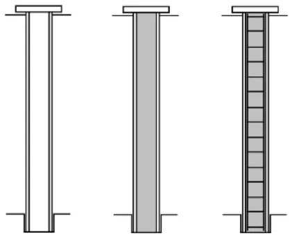
significantly reduced. Steel pipe piles is usually bored with a DTH-hammer but for smaller dimensions a top-hammer can be used. The diameter of the piles usually varies between 100 and 273 mm but piles with a diameter of up 813 mm has been performed in certain projects (Bredenberg, et al., 2010). Different kind of steel pipe piles can be seen in Figure 1.
The design bearing capacity for steel pipe piles is, at least, 500 kN for piles with small diameter and 6000 kN or more for piles with larger diameter. An advantage with bored steel pipe piles is that they can be installed with great accuracy. The difference between its theoretical position and actual position can be held smaller than ±10 mm (Bredenberg, et al., 2010). This is illustrated in Figure 2.
2 Literature survey
4
Figure 1. From left to right, steel pipe pile, steel pipe pile + concrete, steel pipe pile + concrete + reinforcement (Bredenberg, et al., 2010).
Figure 2. Difference between actual and theoretic position of a steel pipe pile (Bredenberg, et al., 2010).
5
These are the most important factors favoring the use of bored steel pipe piles according to Bredenberg et al. (2010).
The depth to bedrock is not too great (preferred depth, 20-30 m). Demand on gentle installation method in terms of vibration and noise. Obstacles for driven piles are expected in the soil.
Displacement piles are not allowed.
When it is very important that the time plan is followed, boring is, in general, a low risk method in terms of productivity.
When low tolerances are required.
Piles have to have high bending moment capacity. The piles have to reach bedrock.
Heavy machines for pile installation are not allowed. 2.2.2 Steel core piles
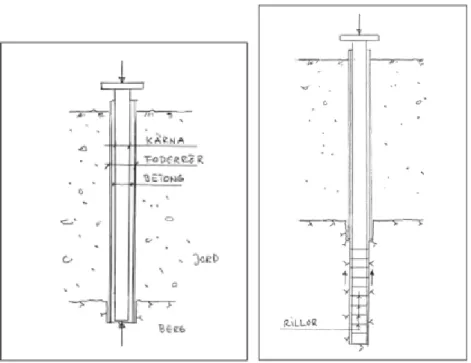
The steel core pile consists of a casing tube which is bored to bedrock. Thereafter a steel core is inserted in the casing tube and finally concrete is casted in the void space between the core and the casing. The steel core pile has the same installation
advantages as the steel pipe pile since both pile types are bored. The difference between them is the core that inserted to the steel core pile, this makes it more expensive than the steel pipe pile but also makes it able to carry much larger loads. Nowadays, sufficient bearing capacity can be achieved even in weaker rock by inserting the core deeper than the casing tube and then grout the void between the core and the bedrock with concrete. This spreads the load from the steel core over a larger rock volume and hence increases the bearing capacity of the pile (Bredenberg, 2000). Figure 3 shows the different methods used for steel core piles.
Below some advantages for the steel core pile are listed. Can also be used for tensile forces
When accurately installed the steel core pile can have a well-known Eigen frequency which can be useful in earthquake areas.
The meter-cost per kN is very high compared with other pile types When installing the steel cores in the casing tubes one must be certain that the bottom of the casing is clean, cleared of drill cuttings and that the casing is properly driven into solid bedrock.
2 Literature survey
6
Figure 3. To the left an end bearing steel core pile and to the right a friction bearing pile (Bredenberg, 2000).
2.3 Drilling
2.3.1 General
When drilling piles there are two different ways of drilling the hole. Either the hammer is mounted at the top of the pile (rotary percussive top drive) or it is
mounted at the base of the pile (rotary percussive down-the-hole-hammering, DTH drilling) (Bredenberg, et al., 2010).
In this thesis the focus is on DTH drilling since top hammers are of limited use because of high noise generation and generally can only drill piles up to 15 m and dimensions up to 200 mm (Bredenberg, et al., 2010).
2.3.2 DTH
For DTH drilling, the drill consists of a drill bit, a casing shoe and a ring set. The drill bit drills the middle of the hole and steers the drill string that is attached to the drill rig. The drill bit has tungsten-carbide points that are extremely hard that crushes the rock. A hammer system is attached directly to the pilot bit. The hammer systems will be described later in the report. The hammer provides the strikes and the drill rig provide the rotation.
7
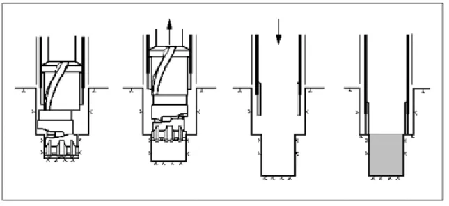
There are two different styles of DTH drilling; eccentric drilling and concentric drilling. In eccentric drilling, a casing shoe is welded to the steel pipe before starting the drilling (Bredenberg, et al., 2010). When the hammer hits the pilot bit the casing shoe is pulled down and transfer impact energy to the casing and enables the casing to move down the hole. The pilot is moving sideways to drill room for the casing and thus the name eccentric drilling. This type of drilling allows the drilling equipment to be extracted when the target depth is reached (Finnish road administration, 2003). In Figure 4, the procedure of eccentric drilling is shown.
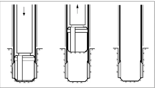
In concentric drilling on the other hand the casing shoe transfers the hammers striking energy to a ring bit that is mounted outside the pilot and drills the outer part of the hole. The ring bit is left in the ground when the target depth is reached and the pilot bit is centered in the casing pipe and can be extracted. This allows for straighter holes and better penetration than eccentric drilling. Concentric drilling is used by a lot of DTH-drilling techniques (Bredenberg, et al., 2010). The ring set acts as a part of the pile after the drilling. In concentric drilling there are two options, either the casing rotates with the ring bit or a rotary joint is used and in that case only the ring bit is rotating. The rotary joint connects the casing shoe and the ring bit and allows the ring bit to rotate alone (Sandvik, 2012). Figure 5 illustrates concentric drilling.
Figure 4. Scheme of eccentric drilling with ODEX, Atlas Copco (Bredenberg, et al., 2010).
2 Literature survey
8
Figure 5. Scheme of concentric drilling (Bredenberg, et al., 2010).
2.3.3 Conventional air DTH drilling
In conventional air systems, the drill hammer is powered by compressed air. Together with the torque applied by the drill rig the hammer drives the pile
downward. In the hammer it is only one part moving and that is the piston. To make it move, air first enters through the backhead/top sub and opens the check valve to flow down further into the lower chamber. From the inflow the pressure rises in the chamber and forces the piston upwards. When it reaches a certain level air is allowed to leave the lower chamber through the bit down to the borehole area. As soon as the lower chamber is empty the top of the piston aligns with an air port that opens the upper chamber for inflow. Air starts flowing into the upper chamber and causes a pressure build up that pushes the piston downwards and begins the striking motion on the pilot bit (Pneumec, 2008). When the hammer hits the drill bit a stress wave propagate through the drill bit and reaches the tungsten-carbide points that induce high point stresses to the soil/rock (Chiang & Elias, 1999). When the hammer strikes the pilot the cycle repeats (Pneumec, 2008). Figure 6 shows a typical air powered DTH – hammer.
The air that flows out to the borehole area is used to flush out the drilled material up through the casing. The drill bit has swivels that allow the material to pass through and enter the casing. The air expands when it leaves the drill bit and pushes the material to the side and it is forced up through the casing outside of the drill bit by the continuing expansion of the compressed air. In the cases when drilling under the ground water level the air rises and in that way the material is flushed but this is described more in chapter 2.3.2.
9
To make sure that the flushing holes stay open during drilling, the pressure generated under the drill bit by the feed force must be lower than the flushing pressure (Finnish road administration, 2003). The direction of the air flushing in a conventional air driven hammer is illustrated in Figure 7.
Figure 6. Example of a DTH-hammer and its parts. 1 Check valve; 2 Valve operated drive; 3 Inner cylinder; 4 Piston; 5 Pilot. (Anon., 2016).
Figure 7. Flushing direction of conventional air powered drilling (Bredenberg, et al., 2014).
2 Literature survey
10 2.3.4 Water DTH drilling
The technology to power a DTH hammer with water pressure was developed by Wassara in 1988 and was developed for the mining industry. The water is not only driving the hammer but also works as lubricate and thus, the drill does not need any oil for lubrication. The hammer works similar to an air-driven DTH hammer but with the difference that the moving parts are the piston and the valve (LKAB Wassara AB, 2015). The valve has different chambers that depending on the control valve’s
position will connect to the high pressure inlet. The driving cycle starts with the opening of the valve which gives an inflow of pressurized water in the lower chamber that makes the piston move up into ready striking position. When the piston is in position, the valve closes and the high pressure water, that is now directed to the upper chamber, pushes the piston downward to strike the drill bit (Tuomas, 2004). When the piston strikes the bit, the valve opens and releases the water through the bit. This restarts the cycle. Figure 8 shows the hammer cycle.
When the water flows out through the drill bit the pressure drops and soon reaches a state of hydrostatic pressure due to the fact that water is an incompressible medium. The water carries the cuttings up to the surface inside the casing with the flow
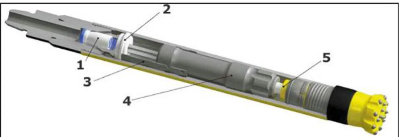
generated from the hammer and according to Wassara the up-hole velocity is low. The parts in the hammer is further visualized in Figure 9.
Figure 8. Description of the hammer striking in a wassara hammer (LKAB Wassara AB, 2015).
11
Figure 9. Wassara DTH hammer - cut through courtesy of Wassara, 2015.
The equipment needed for this technology is:
Drill rig – Holds the pile and hammer and applies the torque needed for rotation.
High pressure pump – builds up the needed water pressure.
High pressure hose – distributes the water to the hammer via the swivel. Swivel – controls the water inflow to the hammer.
Drill tubes – connects the drill rig with the hammer and pilot. Check valve – controls inflow to the hammer cylinder.
Wassara DTH hammer – Produces the strike energy. Drill bit – Performs the drilling action.
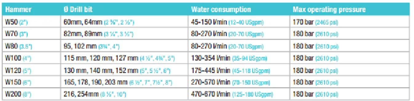
Table 1 shows the available sizes of hammers from Wassara with details of water consumption and operating pressures.
2 Literature survey
12 2.3.5 Modern air drilling
Modern air drilling systems include for example Atlas Elemex system and Sandviks Centrex pro. Both systems rely on the principle of redirecting the air flow in the flushing. Instead of the air flushing in the same direction as the drilling path the air is blown perpendicular to the drilling path. All flushing and cuttings are kept inside the casing and the method is gentle enough to not allow air to escape to the formation but still tough enough to flush the pilot face of drill cuttings (PPV Finland, n.d) (Atlas Copco, 2010). The channels for the flushing to escape are situated above the ring bit cutting edge in the Centrex pro system to minimize air escape to the formation. It is designed with spiral grooves that should push the cuttings out to the flushing
channels so they can be removed smoothly (PPV Finland, n.d). In 2014 an article was published in the journal Bygg och Teknik (Bredenberg, et al., 2014) where a
comparison was made between a conventional air DTH drilling system and the elemex system in terms of settlements. The study showed clearly that drilling with Elemex gave significantly lower settlements, in all measuring points the settlements with Elemex was less than half of those with conventional DTH drilling (Bredenberg, et al., 2014). Figure 10 and 11 shows the pilot faces of the two above mentioned systems.
Figure 10. Drill bit used in Centrex pro system (PPV Finland, n.d).
13
2.4 Causes for settlements during installation
2.4.1 Uptake of excessive material
During the drilling operations, the cutter head is continuously flushed to remove drill cuttings and bring them through the casing up to ground level. When using an air powered hammer, the air used to drive the hammer is also used to flush the cutter head (Bredenberg, et al., 2014). When drilling under the ground water table this might cause an air lift pump-effect which could lead to the uptake of excessive soil (Bredenberg, et al., 2010). The pump effect will cause an upward velocity of the water and air mixture inside the pipe, which in turn, will cause a pressure difference
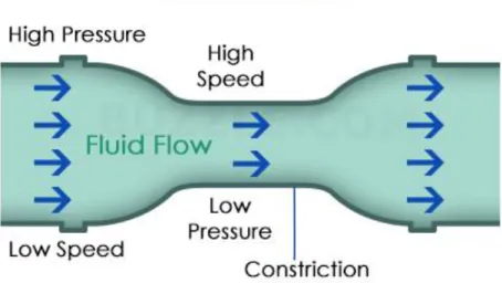
between the moving water inside the pipe and the stagnant water surrounding it, this phenomenon is also called the venturi effect. The pressure difference will cause the surrounding water to flow towards the tip of the pipe, which could result in soil being transported with this flow (Bredenberg, et al., 2014). This phenomenon might also occur when using a water powered hammer and thus flushing the hole with water. The water rising up through the pipe will also have a higher velocity than the water surrounding the pipe but the velocity difference will be much smaller than for the air flush-case, since the water is let out of the drill bit with a much smaller velocity (LKAB Wassara AB, 2015). In Figure 12 the venturi effect is illustrated.
Equation 1 is called Bernoulli’s equation and describes how the pressure, 𝑃, decreases when the velocity, 𝑣,of a fluid increases.
𝑃 = 𝐾 −1
2∗ 𝜌 ∗ 𝑣
2− 𝜌 ∗ 𝑔 ∗ ℎ
𝑤 [1]
, where K is a constant and ℎ𝑤 is the height of the water. This effect can cause huge
void areas around the pile, finally resulting in settlements at ground level around the drilling site. A way to detect this phenomenon is to measure the up taken material and compare it with the theoretical volume of the casing. Sandy, fine grained soils are particularly sensitive to this phenomenon and especially when drilling at larger
depths. In some cases, as much as ten times the theoretical casing volume was taken up while drilling. The phenomenon can, however also occur in clay formations, especially in the interface between clay and harder soils or rock (Langford, et al., 2014). The flushed up material is also dependent on the person conducting the drillings. To further reduce the risk of this phenomenon, experienced and competent personal is a key factor (Bredenberg, et al., 2010).
It should be said that the air lift pumps are also used for dredging, where they are used to suck material from the sea bottom up to the surface. When dredging with an air lift pump, a pipe is submerged in water, thereafter an air hose is connected at the bottom of the pipe. Air is then blown in to the water filled pipe and rises up to the surface. When the air is mixed with the water inside the pipe the average density of the mixture becomes lower than the outside water further increasing the venturi
2 Literature survey
14
effect. This causes the mix inside the pipe to rise to the surface and the water surrounding the pipe starts flowing in through the bottom of the pipe. The suction created is enough to move soil from the bottom up to the surface (Looström, 1996). Figure 13 is an illustration of how the air lift pump works.
Figure 12. Illustration of venturi effect (buzzle.com, 2016).
15
2.4.2 Ground movements due to pore pressure increase
During earthquakes, the cyclic loading of a soil can result in increased pore water pressure, especially in fine grained friction soils. It is possible that this kind of cyclic loading could occur also in pile drilling. This increased pore water pressures then lead to a volumetric strain in the soil when the soil reconsolidates. The type of irregular loads responsible for building up the pore pressure does not affect the volumetric strain but only the buildup of pore water pressure itself.
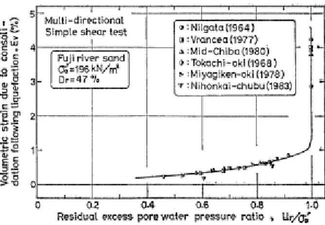
For a non-liquefaction case, i.e. when the pore water pressure does not exceed the total stress, there is a unique correlation between the pore water pressure and the reconsolidation volumetric strain (Nagase & Ishihara, 1988). For example, in a loose, friction soil the reconsolidation strains can reach 1.2 % for the non-liquefaction case. If liquefaction is reached, the volumetric reconsolidation strain can take any value greater than that of the highest non-liquefaction value. In the liquefaction stage it is very hard to predict the magnitude of the reconsolidation strains but it usually
reaches significant higher values than the ones observed for the non-liquefaction case (Nagase & Ishihara, 1988). In Figure 14, Figure 15 and Figure 16, the relationship between volumetric reconsolidation strains and residual pore water ratio can be studied for loose, medium dense and dense soils respectively.
2 Literature survey
16
Figure 14. Volumetric reconsolidation strain versus residual pore water pressure ratio in loose soil (Nagase & Ishihara, 1988).
Figure 15. Volumetric reconsolidation strain versus residual pore water pressure ratio for medium dense soil (Nagase & Ishihara, 1988).
Figure 16. Volumetric reconsolidation strain versus residual pore water pressure ratio for dense soil. (Nagase & Ishihara, 1988).
17
As the figures show there are some differences in the non-liquefaction behavior for the different soil types. A looser soil will in the non-liquefaction case give rise to smaller volumetric reconsolidation strains than a denser soil (Nagase & Ishihara, 1988).
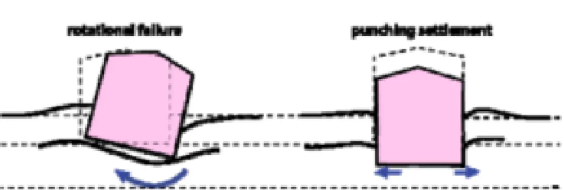
Another effect of increased pore water pressure is the loss of bearing capacity which most often occurs in granulated soils. This state is termed a “quick condition” and several of these bearing capacity failures where observed during the 1964 Nigata earthquake. It then led to several high rise apartment buildings rotating and tipping due to the liquefied soil (Youd, 1973). The figures below show examples of bearing capacity failures that can occur due to stability decrease, which as previously stated can be associated with pore water increase and liquefaction.
In the field study of tie back anchors in Norway the influence zone for pore pressure changes extends up to 5 m from the drill string in some cases and the greatest change in pore pressure from installation of one anchor was recorded to 70 kPa, 1 m from the drill string (Lande & Karlsrud, 2015). This test was performed in soft homogeneous clay.
According to the Finnish road administration (2003), the strength returns slowly after a pore pressure increase and in over-consolidated soils, the strength only partly returns. Figure 17 shows a failure due to loss of stability.
Figure 17. Partial bearing capacity failure due to stability decrease (Bray & Dashti, 2010).
2 Literature survey
18
2.4.3 Ground movements due to pore pressure decrease
As described in section 2.4.2, there is a risk of getting a suction effect at the tip of the pile during drilling and cause an excessive uptake of material. This suction can also affect water and cause a decrease in pore water pressure. Two studies in Norway have shown these effects both by case studies and a full scale field study of drilling tie back anchors in clay. A very small leakage at the base of a clay layer cause a large pore pressure reduction in the base (Langford, et al., 2014).
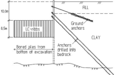
Installation of bored piles and drilled tie back anchors can cause drainage up through the casing or along the outside of the casing. One of the mentioned cases was a 10 m excavation with installment of steel core piles below it of about 20 m length and tie back anchors in the sheet pile. The pore pressure reduction measured at bedrock level was 30 kPa 35 m behind the excavation and according to the authors this is most likely caused by the drilling of both anchors and piles. Of the settlements observed 15 m behind the excavation, around 35 cm was induced by drilling of piles and anchors and consisted of a combination of consolidation due to the pore pressure decrease, over drilling and disturbance during drilling (Langford, et al., 2014). A scheme of the setup is shown in Figure 18.
In the other study the authors point out that if gaps between the casing and the surrounding soil are created during drilling, these gaps work effectively like drainage paths for ground water and reduce pore pressures and thus, induce consolidation settlements in clay. They also state that these drillings are done from a level below the ground level since it is in an excavation. This will increase the unbalance pressure between vertical ground stress and water/air pressure at the head of the drill string when compared to drilling from ground level (Lande & Karlsrud, 2015).
Included in this report is a field study of the drilling of tie back anchors to bedrock through clay and the results show that the largest settlements occur when drilling with ODEX and an air powered DTH hammer and the smallest settlements happen with ODEX with a water powered DTH hammer from Wassara (Lande & Karlsrud, 2015).
19 2.4.4 Settlements due to vibrations
During installation of drilled piles, the equipment generates vibrations. In soils such as loose sand and silt there is risk of getting settlements due to vibrations in the soil. In other soils the vibrations can contribute to settlements but are not often the main source. It is stated by Massarsch & Fellenius (2014) that an important parameter for assessing the risk of settlements due to vibrations is the shear strain that is defined as:
𝛾 =𝑣𝑠
𝑐𝑠 [2]
, where 𝑣𝑠 is the particle velocity measured perpendicular to the wave propagation direction, and 𝑐𝑠 is the shear wave velocity of the medium.
Earlier works have shown that no soil disturbance will occur with shear strain values lower than 0.001 % (Drnevich & Massarsch, 1979). With higher values the risk of particle rearrangement increases and so also the settlements. At 0.010 % the vibrations can start to induce settlements. When the shear strain exceeds 0.100 % there is a severe risk of settlements (Mohamed & Dobry, 1987) (Drnevich &
Massarsch, 1979).
In the article by Massarsch & Fellenius (2014), an example is provided of damage threshold levels for a medium dense sand with an assumed shear wave velocity of 200 m/s. The threshold levels they acquire are the following: no risk: 2 mm/s; low risk: 20 mm/s and high risk: 75 mm/s. These levels are the peak particle velocity in the perpendicular direction of the direction of the vibration propagation (Massarsch & Fellenius, 2014).
2.5 Soil behavior
2.5.1 Introduction
This chapter treats the geotechnical theories that are associated with the phenomena described in chapter 2.4. It is important to have this theory to understand why these phenomena can occur during drilling.
2.5.2 Pore pressure
One of the fundamental principles of geotechnics is the theory of effective stress. The theory states that the effective stress is the difference between total stress and the stress carried by the pore water pressure (or other fluid pressure)
𝜎′0 = 𝜎0− 𝑢 [3]
Here the subject of pore water pressure is described since it is an important aspect related to pile drilling. During drilling the pore pressure can both increase and decrease. Therefore, fundamental pore pressure theory is described below. In a soil there are voids between the mineral/clay particles that either is filled with gas or water (Larsson, 2008). Per definition of the ground water level all voids below it are filled with water. An illustration of the pore structure of a soil is illustrated in Figure 19.
2 Literature survey
20
Figure 19. Soil particles and voids (Larsson, 2008).
The total pore pressure can be divided into components that, put together ads up to the total pressure. According to Mitchell (XXXX), there are four components to the total pore pressure in a surrounding with constant temperature:
1. Gravity pressure, z, - that arises from the difference in elevation between two points.
2. Hydrostatic pressure, p – arises in reaction to external stresses. This is the pressure that would be registered by a pressure sensor if installed at that point. 3. Osmotic pressure, π – arises from differences in ionic concentration between
two points.
4. Adsorption pressure, a – arises from clay surfaces attraction of water molecules.
Negative pore pressures can and do exist in soils. The causes for this is due to osmotic and adsorptive effects (Mitchell, n.d). In saturated soils negative pore pressures are usually results of osmotic effects, hydrostatic stresses from a dilating tendency on shear and from hydrostatic effects that is caused by the stresses carried by bent particles and distorted particle groups. In partially saturated soils the surface tension in water along with adsorptive forces result in a curved air/water interface that lead to additional pressures. Depending on if the curvature is convex or concave the additional pressure is negative or positive.
When a load is applied on a soil the soil is compressed and the soil grains move closer together. However, if the voids are filled with water, that is incompressible, the soil does not compress but the pore pressure increase instead. Soils are permeable so in this sequence water dissipates through the soil and the soil can be compressed as the pore pressure decrease. This is what in text books is called consolidation of a soil.
21
An example of pore pressure builds up is explained in Strout & Tjelta (2005). If a continuous loading through sedimentation is applied at a higher rate than the soil can dissipate excess pore water, which depends on the permeability of the soil, a pore pressure builds up occurs and is trapped in the soil layer.
2.5.3 Hydraulic conductivity of soils
The hydraulic conductivity is an important factor that is connected to drilling of piles. The hydraulic conductivity of a soil affect the size of the area disturbed by the drilling, how large the air lift pump effect will be and the time needed to dissipate excess pore pressures that can arise during drilling.
Since soil has voids that are interconnected the soil is permeable and water can flow through the soil (Das & Sobhan, 2010). In 1856 Henry Darcy proposed an equation that describes the flow velocity through the soil now known as Darcys law.
𝑣 = 𝑘 ∗ 𝑖 [4]
In [4] 𝑣 is the discharge velocity, 𝑘 is the hydraulic conductivity and 𝑖 is the hydraulic gradient that is expressed as the head loss in pressure head level divided by the
distance between the points in the flow direction. Hydraulic conductivity is expressed in m/sec and depend on various factors such as: fluid viscosity, pore-size distribution, grain-size distribution, void ratio, roughness of mineral particles and degree of soil saturation. In unsaturated soils the hydraulic conductivity is generally lower and increases with degree of saturation (Das & Sobhan, 2010).
A soil with larger particles usually have larger pore channels and these soils have a high hydraulic conductivity. But since the soil structure can vary widely in terms of pore channel formation the hydraulic conductivity varies along with this. Especially in compacted clays the hydraulic conductivity can vary even though two compacted clays have the same molding water content and maximum dry density. This is because of the complex nature of clays and depend on the clay mineral type and the type and energy of compaction (Reddi, 2003). In Table 2 below some typical values of hydraulic conductivity for different saturated soils is shown.
Table 2. Typical values for hydraulic conductivity for different saturated soils.
Soil type k (cm/sec)
Clean gravel 100-1.0
Course sand 1.0-0.1
Fine sand 0.01-0.001
Silty clay 0.001-0.00001
2 Literature survey
22
The hydraulic conductivity controls the seepage in the soil and is necessary to know to estimate the seepage. Seepage is the phenomenon when the water in the soil flows through the soil. The flow can be either upwards or downwards in the soil and this cause differences in the effective stress of the soil. It can both increase and decrease the effective stress depending on the direction of the flow. The seepage causes a pressure head drop that is the reason for the change in effective stress compared to the case with no seepage. An upward seepage causes a lower effective stress than with no seepage and a downward flow causes an increase in effective stress compared to with no seepage. With a high enough upward seepage the soil reaches a critical state when the effective stress equals zero and all stability is lost. This is known as boiling/
quick condition (Das & Sobhan, 2010).
2.5.4 Settlements
Since drilling can cause consolidation or re-consolidation of a soil this chapter gives a general description of settlement theory.
A stress increase in a soil compresses the soil layers as is described earlier in the report. The compression is caused by three things; deformation of the soil particles, relocation of the particles and dissipation of water or air from the void spaces. The settlements can be divided into three categories (Das & Sobhan, 2010).
Elastic settlement – is caused by elastic deformation of soil without any change in
moisture content. In (Das & Sobhan, 2010) the calculation of the elastic settlement for a perfect flexible foundation is expressed as:
𝑆𝑒 = ∆𝜎(𝛼𝐵′)1−𝜇2
𝐸𝑠 𝐼𝑠𝐼𝑓 [5]
, where ∆𝜎 is the net applied pressure, 𝜇 is poisson’s ratio, 𝐵′ is the effective width of
the foundation, 𝐸𝑠 is the elastic modulus for the soil, 𝐼𝑠 is a shape factor and 𝐼𝑓 is a depth factor.
Primary consolidation settlement – is caused by the volume change in saturated soil
that happens when pore water dissipates. These are also dependent on the net
pressure acting on the soil. There are various ways of calculating the settlements and in Sweden the most common way is by using compression moduli and the CRS-method. The formulas are based on CRS-tests done on clay (Larsson, 2008). The formulas differ depending on where on the stress-strain curve that the soils in situ condition is. It can be said to have three phases; 1. Below the pre-consolidation pressure; 2. Under the limit pressure; 3. beyond the limit pressure.
23
For the case when 𝜎′𝑐 < 𝜎′𝑣0+ ∆𝜎′𝑣 < 𝜎′𝐿 𝑎𝑛𝑑 𝜎′𝑣𝑜< 𝜎′𝑐:
𝑠 = 𝛴ℎ (𝜎′𝑐−𝜎′𝑣0
𝑀0 +
𝜎′𝑣0+∆𝜎′𝑣−𝜎′𝑐
𝑀𝐿 ) [6]
For the case when 𝜎′𝑐 < 𝜎′𝑣0+ ∆𝜎′𝑣 < 𝜎′𝐿 𝑎𝑛𝑑 𝜎′𝑣𝑜 ≥ 𝜎′𝑐
𝑠 = 𝛴ℎ (∆𝜎′𝑣
𝑀𝐿) [7]
For the case when 𝜎′𝑣0+ ∆𝜎′𝑣 ≥ 𝜎′𝐿 𝑎𝑛𝑑 𝜎′𝑣𝑜 ≤ 𝜎′𝑐 𝑠 = 𝛴ℎ (𝜎′𝑐−𝜎′𝑣0 𝑀0 + 𝜎′𝐿−𝜎′𝑐 𝑀𝐿 + 1 𝑀′ln 𝜎′𝑣0+∆𝜎′𝑣−𝑎 𝜎′𝐿−𝑎 ) [8] Where 𝑎 = 𝜎′𝐿−𝑀𝐿 𝑀′
For the case when 𝜎′𝑣0+ ∆𝜎′𝑣 ≥ 𝜎′𝐿 𝑎𝑛𝑑 𝜎′𝑣𝑜 > 𝜎′𝑐
𝑠 = 𝛴ℎ (𝜎′𝐿−𝜎′𝑣0 𝑀𝐿 + 1 𝑀′ln 𝜎′𝑣0+∆𝜎′𝑣−𝑎 𝜎′𝐿−𝑎 ) [9]
Secondary consolidation settlement – is caused by plastic adjustment of soil fabrics
and happens in saturated cohesive soils and in organic soils. It is another form of compression and occurs at constant effective stress.
The total settlement of a foundation or other structure is all these added together. An increase in effective stress, no matter the source can cause settlements so for an example, if there is a pore pressure decrease or a downward seepage the effective stress increase and can cause a settlement even though the external load has not changed.
Cohesionless soil such as sand are most often highly permeable and the process of dissipation of excess pore water happens quickly. Thus, the consolidation settlement happens simultaneously as the elastic settlements. In these types of soil, no secondary consolidation settlements occur. The elastic settlements are estimated by equations that are derived from the elastic theory.
In cohesive soils, all of the abovementioned types of settlements occurs. The elastic settlements happen immediately. As seen in chapter 2.3.2 above cohesive soils has a much smaller hydraulic conductivity than cohesionless soils and the consolidation takes longer to develop and continues long after the elastic settlements. In clays the consolidation settlements can be many times larger than the elastic settlements (Das & Sobhan, 2010).
2 Literature survey
24
2.6 Measurement equipment
2.6.1 Settlement screw
A settlement screw is used to acquire the settlements in a point located beneath the ground surface. The settlement screw consists of a short screw attached to a steel rod, the screw is screwed down to the depth were settlements is to be measured and is thereby firmly anchored in the soil. The settlements at that exact depth can then be measured at the tip of the rod located at above ground surface, using reference points. An illustration of a settlement screw can be seen in Figure 20 (Roadex network, 2014).
25 2.6.2 Pore pressure sensor(piezometer)
The pore pressure sensor consists of a pore pressure sensor and filter tip. The sensor itself is used to measure the level of the ground water table in open tubes. When measuring the pore water pressure in a soil it is equipped with a filter tip to keep soil from entering the sensor (Geometrik, 2016). Figure 21 show the pore pressure sensor and the filter tip.
To measure the pore water pressure in a soil, a hole with suiting diameter is first drilled. Then a tube with the pressure sensor and filter tip mounted on it is lowered in to the hole and pushed into the ground (Geometrik, 2016).
Figure 21. Pore pressure sensor and its parts, type BAT-
2 Literature survey
26
2.7 Summary and conclusion from literature survey
The main difference between the studied drilling techniques is that the transport of the drill cuttings is made with compressed air contra water. Besides that, the hammer works principally in the same way for both methods. The operating pressures are quite different with air at around 24 bar and water at 170 bar fed to the hammer. However, when the water leaves the hammer and enter the drill bit area the pressure drops quickly towards hydrostatic pressure. Problems can still arise if the water is stopped from evacuating through the casing, this could lead to an increase in pore water pressure in the soil. The disturbance of the soil seems to be induced mostly by flushing which influences the settlements during installation.
When compressed air is used for flushing the bore hole there is a risk of flushing up excess material, when drilling under the ground water level this risk is enhanced due to the so called air-lift pump effect. When more material than the bore hole volume is flushed up there will always be settlements. Most of the settlements in clays that can occur during drilling seems to be related to changes in pore pressures. If the pore pressure in the clay is increased, it could lead to reconsolidation and settlements in the soil or bearing capacity failures. The pore water pressure can also be decreased during drilling, due to the creation of drainage paths in gaps between the casing and the surrounding soil. This leads to consolidation of the soil and can cause severe settlements at ground level. Vibrations does not contribute much to settlements during drilling since the vibrations induced by the drilling are relatively low. The main conclusions from the survey are that settlements, both in depth and at ground surface, and pore pressure changes are the best parameters to measure when trying to assess the soil influence caused by pile drilling.
27
3 Field study
3.1 Work site
The field study was conducted during the 23-24th of May 2016 at Trafikplats Vega, a
Swedish transport administration project in Haninge outside Stockholm where Skanska is the main contractor. In the project, they are constructing an interchange with several ramps and a roundabout above the existing road. The test was not part of the production but was performed on Norrby gärde on the project site, see Figure 22 for illustration. The test was performed in two test groups and at each test group a weight sounding was performed beforehand. Each group consisted of two test piles and measurement equipment as described in Figure 23. The piles in test group 1 were drilled using air powered drilling and the piles in test group 2 were drilled with water powered drilling.
3 Field study
28
The geological conditions varied on the site, but the test was performed on a part of the site that had homogenous conditions. The soil was mostly very soft clay with an underlying layer of frictional soil and silt on the bedrock. From previous soil/rock probing and weight soundings in nearby locations, an approximate soil profile and depth was determined for the test site in order to select the most suitable site. The ground surface was at a level of +24.3 m for both test groups. From a measurement in a ground water pipe, the ground water level was measured to +23.3 m. The surface on the test site was flat and partly covered with a 0.2-0.3 m thick fill of crushed rock. An illustration of the test site and setup can be seen in Figure 24.
29
3.2 Drilling equipment and piles
The drill rig used was one from Skanska Grundläggning and it was a Volvo EC210C equipped with a drilling aggregate from SPD. The rig could load pipes of up to 6 m in length. The piles used were Ruukki RD-piles with welded joints, an outer diameter of 139.7 mm and steel thickness of 8 mm. For both drilling methods a pilot from Atlas Copco was used. For the air drilling, the only equipment needed besides the drill rig was a compressor from Atlas Copco that could feed a pressure of 20 bar to the hammer. The water hammer used was a Wassara W100, a 4-inch hammer. Besides that, a high pressure water pump was needed to pressurize the water up to the necessary pressure before feeding it to the hammer. A separate water tank was also used in order to be able to keep drilling for a longer time due to insufficient water supply since the water came from a regular communal water connection and not from a fire hydrant which is recommended if available. To pump the water from the
separate water tank to the high pressure pump a feeder pump had to be used as well.
3.3 Measurement equipment installation
The installation of the measurement equipment was performed by Tyréns on the 17th
of May 2016. Before installing the equipment, a weight sounding was performed at each test group, see Figure 28 and 29, to get a more accurate soil profile and an exact soil depth at those positions. At one of the groups, the surface was covered with the fill so the fill had to be removed before installing the equipment and for the test groups to have similar conditions. The installed equipment consists of:
2 pore pressure sensors at level +19.3 m. 2 settlement screw at level +16.3 m.
2 settlement plates at ground level +24.3 m.
The pore pressure tips and the settlement screws were delivered by Geomek,
including the pipes necessary to install them at the desired depth. The pore pressure sensors and calibration of the gauges were delivered and performed by Geometrik the 19th of May 2016. Figure 24 and 25 show a pore pressure tip and a settlement screw
respectively.
The settlement screw was screwed down to the decided depth with the geo rig. Before installing the ground water pipe with the BAT tip a hole had to be drilled to the desired depth. The pipe with the tip was then pushed down into the hole carefully to not destroy the tip. The tip was also deaerated and filled with water. The sensor was then applied with a needle to be able to penetrate the BAT tip and lowered down through the pipe and into the BAT tip. The readings were made manually with a hand held device. Both the settlement screws and the settlement plates position were exactly determined through surveying with a total station before and after the test to measure the settlements.
3 Field study
30
Figure 24. Pore pressure type BAT MK III.
31
The settlement plates were placed close to the settlement screw at each site to get a comparison between settlements in depth and on the surface. The plates and the screws were measured by a surveyor using a total station. At each test group the settlement screw was installed 1 m from where the piles should be drilled and the pore pressure sensor 1 m behind the settlement screw. This was because the literature survey suggested that the settlements occur close to the drilling while pore pressure changes can occur at greater distance from the piles. The reason for installing the settlement screws at 8 m depth and the pore pressure sensors at 5 m depth was because the weight sounding indicated silt/friction soil at about 8 m and we wanted to place the pore pressure sensors in the middle of the clay layer. Since the literature survey showed that friction soil below the ground water table was most sensitive for settlements when drilling it was decided to place the settlement screws where those soils existed. In Figure 26 the setup of the test groups is shown.
The weight soundings showed that the depth at both pile groups were very similar, 12 respectively 11 m. The results of the weight soundings are showed below in Figure 27-28. The equipment was installed with a small geo rig, see Figure 29.
3 Field study
32
Figure 27. Weight sounding from test group 2.
Figure 28. Weight sounding from test group 1.
33
Figure 29. Geo rig used for installation of measurement equipment
3.3.1 Measuring of pore pressures
The measuring of the pore pressures was done, as stated before, with a hand held device that measured the electric current in the sensor. The electric current can be translated into pore pressure since the device was calibrated against pore pressures relative to the atmospheric pressure. The calibration of the device and the sensors was made by Geometrik and is shown below in table 3 and 4. The pore pressures were then calculated for both sensors after all the measurements by the following formula:
𝑢 = 𝑚𝑒𝑎𝑠𝑢𝑟𝑒𝑑 𝑐𝑢𝑟𝑟𝑒𝑛𝑡−𝑐𝑢𝑟𝑟𝑒𝑛𝑡𝑢=0
𝑐𝑢𝑟𝑟𝑒𝑛𝑡𝑠𝑡𝑒𝑝 ∗ 20 [10]
Calibration
Table 3. Calibration of sensor 16T01.
Sensor 16T01
Current step = 5.614-4.012=1.602
Current (mA) Pore pressure (kPa)
4.012 0
5.614 20
7.216 40
Table 4. Calibration of sensor 16T02.
Sensor 16T02
Current step = 5.732-4.126=1.606
Current (mA) Pore pressure (kPa)
4.126 0
5.732 20
3 Field study
34
3.4 Test drilling
3.4.1 Air powered drilling
Day 1, two piles were drilled at test group 1 using the air method. Due to the
previously performed weight sounding, the geological profile was known to a depth of 12 m. According to the drill operator, the following soil structure for pile 1 probably was hard moraine or soft bedrock between 12-14.2 m and thereafter hard bedrock until the final depth of 14.7 m. For pile 2 it was hard moraine or soft bedrock between 13 and 13.65 m and thereafter hard bedrock until the final depth of 14.15 m. Both piles were drilled using two 6 m pipes and one 3 m pipe, 1 m pipe were left sticking out of the ground in order to be able to weld the joints properly. During drilling, the pore pressure was measured every drilled meter at the pore pressure sensor located in the same test group as the drilled piles, and thereafter regularly until a stable pressure was reached. The pore pressures in the other test group were only measured before, and after the drilling of each pile. Stops were made for welding the pile joints and for lunch between the two piles. To be able to know how deep the pile was drilled at any given time, the piles were marked with spray paint at every meter, as seen in Figure 30. The stop between the piles was also made to give the pore pressure tip time to adjust for the increased pore pressure caused by the pile drilling.
35
Figure 30. Pre-marked test pile.
During drilling, waves in the ground was observed moving out from the drilled piles and air bubbles were coming out of the measurement pit, especially around the ground water pipe holding the pore pressure tip. This suggests that the soil around the pile definitely was affected in some way which also was seen in the test results later on. Otherwise the drilling went smoothly and the air powered hammer was driven at a pressure of 20 bar.
3 Field study
36 3.4.2 Water powered drilling
Day 2, two piles were drilled at test group 2 using the water method. Also here the geology was known but to a depth of 11 m. According to the drill operator the following soil structure for pile 3 probably was soft soil between 11 and 11.7 m, hard moraine between 11.7 and 12 m and then hard bedrock until the final depth of 12.5 m. For pile 4, soft soil was assumed between 11 and 12 m, hard moraine or soft bedrock between 12 and 13 m and then hard bedrock until the final depth of 13.4 m. The pore pressure was measured in the same way as for test group 1. When drilling with water no reactions at the surface could be observed and it produced much less dust than the air powered drilling. However, the drill operator meant that the sinking of the
hammer was a bit slower than for the air powered drilling. Figure 31 shows the test site when drilling with a water powered drill hammer.
37 3.4.3 Measurement of drill cuttings
During the test the drill cuttings were measured for both drilling methods. To be able to do this, the drill cuttings had to be collected and the collection had to be done differently for the two methods. For the air drilling, the drill rig was fitted with a collector house that directed the flushed up cuttings onto geotextile.
With water drilling a basin was constructed since the particles dissolves in water. The basin was built with a 20 cm high edge and a geotextile as bottom. The edges kept the drill cuttings on the geotextile while the water was allowed to exit through it, leaving only the cuttings on the geotextile after the drilling. The basin for assembling the cuttings from water drilling can be seen in Figure 31.
The cuttings were then measured for both methods by shoveling the cuttings into buckets of known volume.
3.5 Limitations
The geological conditions were limited to our test site. The two groups of piles were not possible or suitable to be installed directly besides one another which gives the limitation that the pile length to install was slightly different for the groups. Due to limited time at the project the settlements and pore pressures could not be measured over a longer period but only during and immediately after the drilling. The
equipment and resources needed to measure drill cuttings properly could not be provided and thus, the measurement of those were made as detailed as possible through an own invention.
3.6 Lessons learned from the field study
Doing a field study is a lot of work, most of the work was to plan the field study and organize it along with the project owner, the contractor and the consultants that install measurement equipment. When it comes to geotechnical measurement equipment and installation it turned out to be more complicated than we expected. To acquire all equipment needed and install it we had to be in contact with three different companies. Two to supply and calibrate the equipment and one for
installing the equipment. Even if the field study seems to be simple in the beginning it takes a lot of time to involve all parties needed and get them to agree on time and place. Due to limitations we had to invent our own way of measuring the drill cuttings and this was done according to chapter 3.4.3 and it worked quite well.
3 Field study
39
4 Results
4.1 Introduction
In this chapter the results from the measurements carried out during the field study are presented. The results from each type of measurement are divided in sections where one presents the results from air powered drilling and the other from water powered drilling.
4.2 Pore pressure
4.2.1 Pore pressure changes with air powered drilling
It was observed that the pore pressure increased in sensor 16T01 throughout the drilling of the piles in test group 1. Once the drilling stopped the pressure started to decrease and decline towards its initial value as seen in Figure 34. The pressure in the sensor in test group 2, 16T02, was unaffected by the drilling of the piles in test group 1 as seen in Figure 35. In the time between drilling pile 1 and pile 2 the
pressure stabilized but never started to drop. Instead it worked like a continuous step by step buildup of pressure, this can be seen in Figure 32. The pressure at the
measuring level increased from 36 kPa to 50 kPa during the whole process of the drilling of the two piles. It took approximately two days for the pore pressure to return to its original value as seen in Figure 34.
Figure 32 shows the pore pressure change as a function of the total drilled meters with air powered drilling during drilling of both piles. The drilled meters of the piles are super positioned in the graph to visualize the continued increase of pore pressure. When drilling pile 1, the pore pressure was stable until a depth of around 11 m. This was around the time when the drilling had to be stopped to weld on the last pipe to the pile. From that point the pressure kept increasing until 45 minutes after the drilling was completed. After that the pressure was stable until the drilling of pile 2 started. The pressure started increasing immediately when the drilling of pile 2 started although it was a very slow increase in the beginning. At around 4 drilled meters of pile 2 the pressure increased more rapidly and continued throughout the whole drilling process.
Figure 32. Pore pressure change as function of drilled meters for sensor 16T01 during air drilling. 35 36 37 38 39 40 41 42 43 44 45 46 47 48 49 50 51 0 5 10 15 20 25 30 Po re p res su re [kP a] Drilled meters [m] End of pile 1 End of pile 2
4 Results
40
4.2.2 Pore pressure changes with water powered drilling
During the water powered drilling only small changes in pore pressures were observed in sensor 16T02 as can be seen in Figure 33. From the start point of
measuring, the pore pressure in sensor 16T02 was stable until after pile 3 was drilled. The increase in pore pressure was mostly happening in the pause between drilling pile 3 and 4 see Figure 35. The pressure rose from 37 kPa to 40 kPa and reached its maximum value around 15 minutes after the drilling of pile 4 was completed. From that point it started declining slowly. The sensor 16T01 was not disturbed by the drilling of the piles in test group 2. This can be seen in Figure 34 as the pore pressure in that sensor keeps declining in the same way as before the drilling of pile 3 and 4. In Figure 33 below the pore pressure change is plotted against the meters drilled with water powered drilling. The pore pressure did basically not change at all during the drilling of pile 3. It dropped a little the first few meters but recovered to its initial value at 5 m depth. The increase in pore pressure started after pile 3 was drilled and increased until drilling of pile 4 was initiated. During the second drilling the same phenomena occurred, at first the pressure dropped for around 4 drilled meters and then started increasing. The difference is that instead of stagnating when it reached the initial value it kept increasing for the rest of the drilling.
Figure 33. Pore pressure change as function of drilled meters for sensor 16T02 during water drilling. 35 36 37 38 39 40 41 42 43 44 45 46 47 48 49 50 51 0 5 10 15 20 25 30 Po re p res su re [kP a] Drilled meters [m] end of pile 3 drilling end of pile 4 drilling
41 4.2.3 Pore pressure summary
Below, the pore pressure changes in both sensors throughout the whole field study is presented. Figure 34 shows the pore pressure change in sensor 16T01 and Figure 35 shows the change in sensor 16T02.
With both methods an increase in pore pressure was observed during and short after drilling. The increase was significantly higher when drilling with compressed air as can be seen below in Table 5.
Figure 34. Pore pressure change in sensor 16T01.
Figure 35. Pore pressure change in sensor 16T02.
Table 5. Pore pressures during drilling.
Air Water uinitial (kPa) 35,99 37,29 umax (kPa) 49,86 40,22 difference (kPa) 13,87 2,94 30 31 32 33 34 35 36 37 38 39 40 41 42 43 44 45 46 47 48 49 50 51 52
23-maj 24-maj 25-maj 26-maj 27-maj
Po re p res su re [kP a] Time drilling pile 1 10:10-10:52 drilling pile 2 12:20-12:57 drilling pile 3 10:30-11:23 drilling pile 4 12:40-13:15 30 31 32 33 34 35 36 37 38 39 40 41 42 43 44 45 46 47 48 49 50 51 52
23-maj 24-maj 25-maj 26-maj 27-maj
Po re p res su re [kP a] Time drilling pile 1 10:10-10:52 drilling pile 2 12:20-12:57 drilling pile 3 10:30-11:23 drilling pile 4 12:40-13:15